When it comes to designing complex, organic parts, we — as engineers and designers — have many options in the SOLIDWORKS suite. Among those tools, by far the most popular is SOLIDWORKS 3D CAD with its robust and well-proven parametric solid and surface modeling tools.
But with the addition of xApps on the 3DEXPERIENCE platform, we also have access to cloud CAD tools. This includes xShape, which offers a unique type of modeling many SOLIDWORKS users may not be familiar with.
Both SOLIDWORKS and xShape provide powerful sets of tools to create complex geometries and smooth, organic parts — but each has its own specific strengths. Here, we’ll compare both to evaluate their strengths.
What Is xShape?
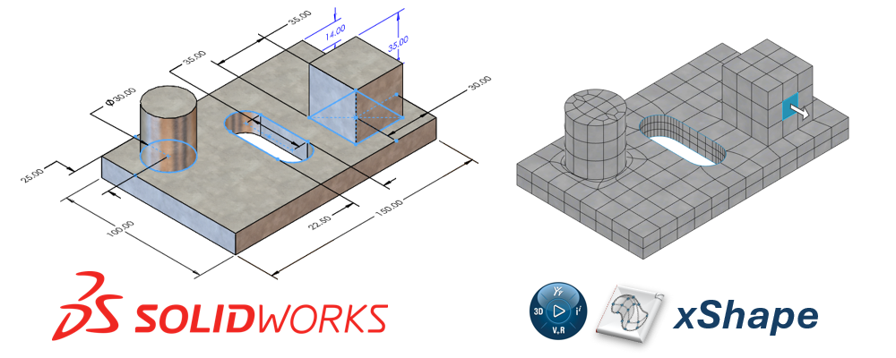
xShape, as part of the 3D Sculptor role on the 3DEXPERIENCE platform, utilizes subdivision or “sub-D” surface modeling to create freeform shapes.
Sub-D modeling is often referred to as modeling with “digital clay” where we “push” and “pull” our geometry instead of defining distinct dimensions like we do in SOLIDWORKS.
If you want to get up to speed with Sub-D modeling, we’ve covered different aspects of xShape and the 3D Sculptor role in these blogs:
- Subdivision Modeling Made Easy Using 3DSculptor
- 6 Tips and Tricks for Sub-D Modeling in 3DEXPERIENCE xShape
- 3 SOLIDWORKS Options Explained: Choosing Your 3D CAD Tool
- SOLIDWORKS + xShape: Utilizing the Power of Parametric and Sub-D Modeling Together
Comparing Core Modeling Approach: Parametric vs. Subdivision Surfaces
SOLIDWORKS and xShape take different approaches to surface modeling — each with its strengths. One is more precise and with models defined by specific parameters while the other is more flexible and freeform.
SOLIDWORKS: Parametric Surface Modeling
In SOLIDWORKS, every part of the model is defined by specific parameters (hence the name “parametric”). This approach provides a high level of precision and control, making it ideal for engineering applications where accurate dimensions, tolerances, and manufacturability are critical.
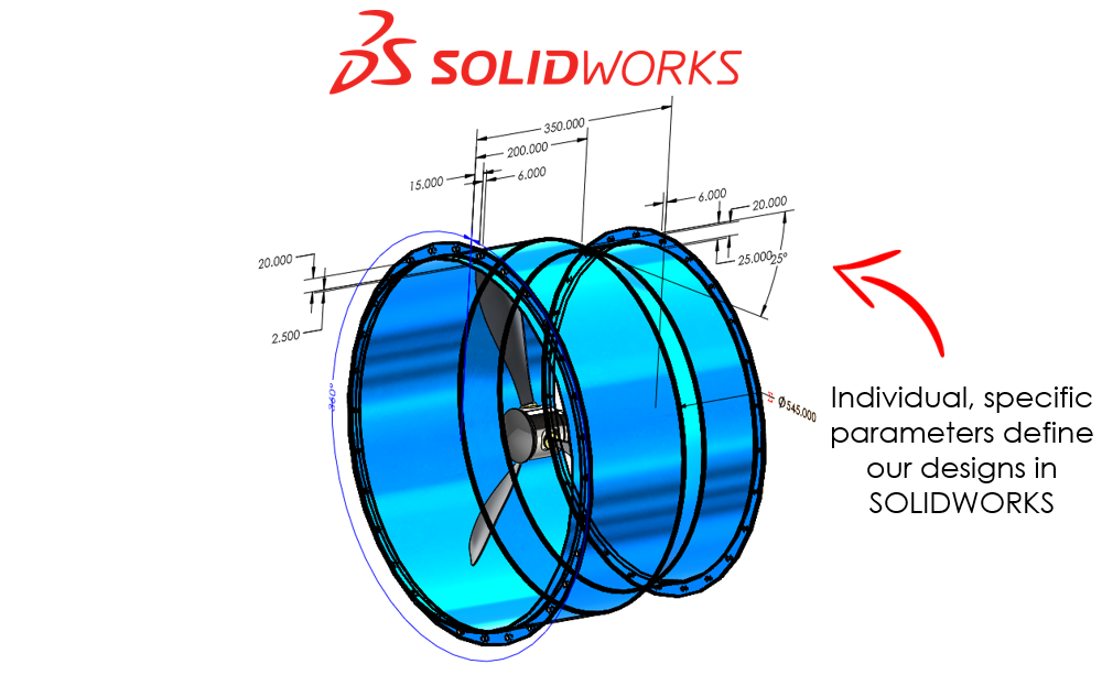
Surface modeling gives us a high level of control over every single face and edge in our model. Many of the common surface modeling features in SOLIDWORKS are similar to regular solid features, such as extrudes, revolves, boundaries, and lofts.
The key difference being that we are working with surface bodies instead of solids.
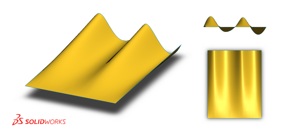
In addition to the more familiar surfacing features, SOLIDWORKS also has powerful surfacing tools that greatly expand our modeling capabilities. These include:
- Delete Face: Delete, create, or modify existing surfaces and create new ones.
- Ruled Surface: Creates a surface along an existing edge in a specified direction.
- Offset Surface: Creates a surface offset from existing geometry — particularly useful for quickly duplicating surfaces/faces.
- Replace Face: Replaces a face on a body with a new surface — helpful for modifying existing geometry quickly and easily.
- Filled Surface: Creates a new surface using existing geometry as a boundary with options for curvature continuity for seamless transitions between faces of a part.
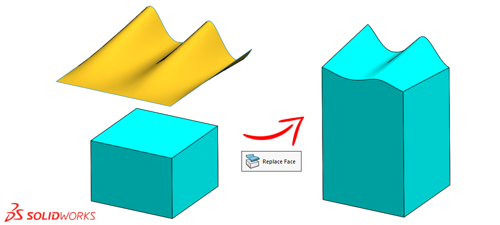
These tools allow designers to build complex 3D geometries with a high level of control that are well-suited to a wide range of applications — all defined by parameters.
Surface Modeling Resources
If you want to learn more about surface modeling in SOLIDWORKS in general, check out these resources:
Blogs
- How to Blend Corners in SOLIDWORKS
- How to Create a Three (or More!) Piece Mold in SOLIDWORKS
- Filled Surface Command in SOLIDWORKS
YouTube Videos
- SOLIDWORKS – Using Knit Feature for Surface Modeling
- SOLIDWORKS – Create a Surface with Varying Tangency
Additional Learning Resources
xShape: Subdivision Surface Modeling
In xShape, we create our parts by subdividing the faces of a model and manipulating those subdivisions. Unlike the “rigid,” parameter-based approach of SOLIDWORKS, subdivision modeling is more flexible and freeform.
It can be especially useful in the design of consumer products where aesthetics and ergonomics may be a key aspect of the design.
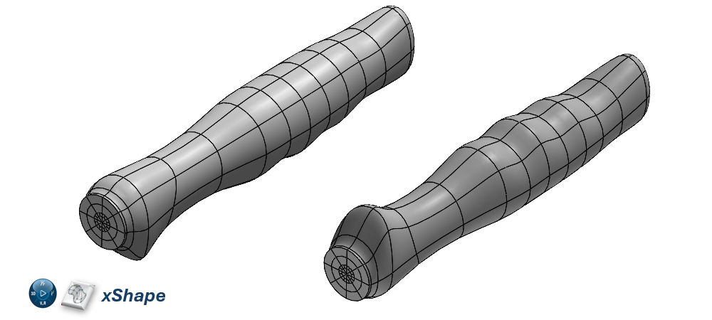
With subdivision surface modeling, we typically aren’t adhering to strict parameters. Instead, we’ll often have some broader geometric requirements and general guidelines to drive our designs.
For example, we might use this cool trick with an image or conceptual drawing to help guide our designs.
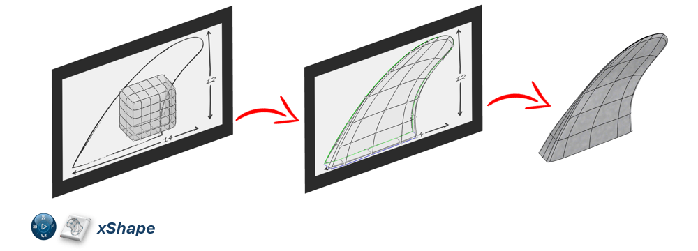
Some of the most useful functionality in xShape includes:
- The Modifier Robot: Allows us to precisely control the direction we want to push and pull our geometry in.
- Direct Numeric Input: Enables numeric input of how far a given vertex, edge, or face is pushed or pulled for greater control.
- Subdivision Refinement: Refine or coarsen the mesh of subdivided faces to gain the exact level of control we need.
- Symmetric Modeling: Automatically mirror changes across a plane of symmetry for efficient modeling of symmetric parts.
- Creasing and Aligning Geometry: Allows us to align our subdivision surface to existing geometry or sketches and creates sharp edges (creases) as required by our designs.
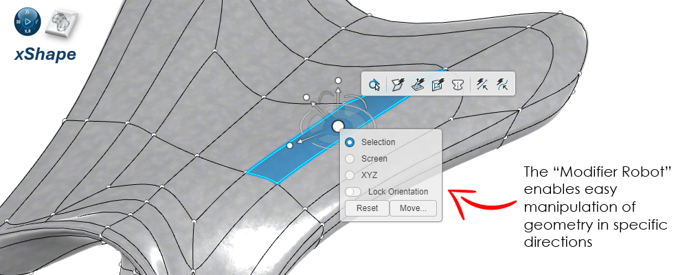
Subdivision modeling is often seen as a more intuitive, form-driven approach, allowing for the creation of complex, flowing geometries without the need to define a large number of parameters.
Exploring Precision and Control
Now, let’s explore precision and control for each tool. Because of the differences in core modeling approaches, each tool has its strengths when it comes to precision and control over our models.
Surface modeling and the type of controls we have access to as we design allow us to create similar models in both tools, but how we create and control them is very different.
SOLIDWORKS Surface Modeling: Precise and Rigid Control
The parametric nature of SOLIDWORKS is often a huge advantage for engineering design. Every single surface (and solid!) is defined by a set of parameters. As a result, SOLIDWORKS surface modeling excels in scenarios where precise control over dimensions and tolerances is required.
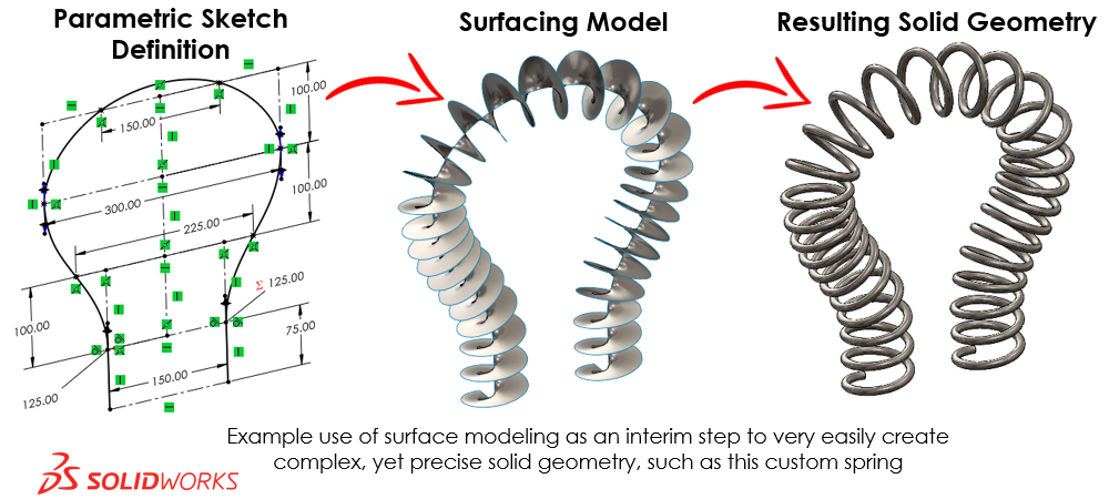
This is often the case for mechanical parts where dimensions and tolerances are key to the form, fit, and function of a design. It also enables a straightforward process of modifying our designs as we can add, remove, and update the individual parameters that control our designs.
For example, with a boundary surface as shown below, we can precisely control each dimension, sketch relation, level and direction of tangency, connector location, and so on for every single set of curves that makes up the surface.
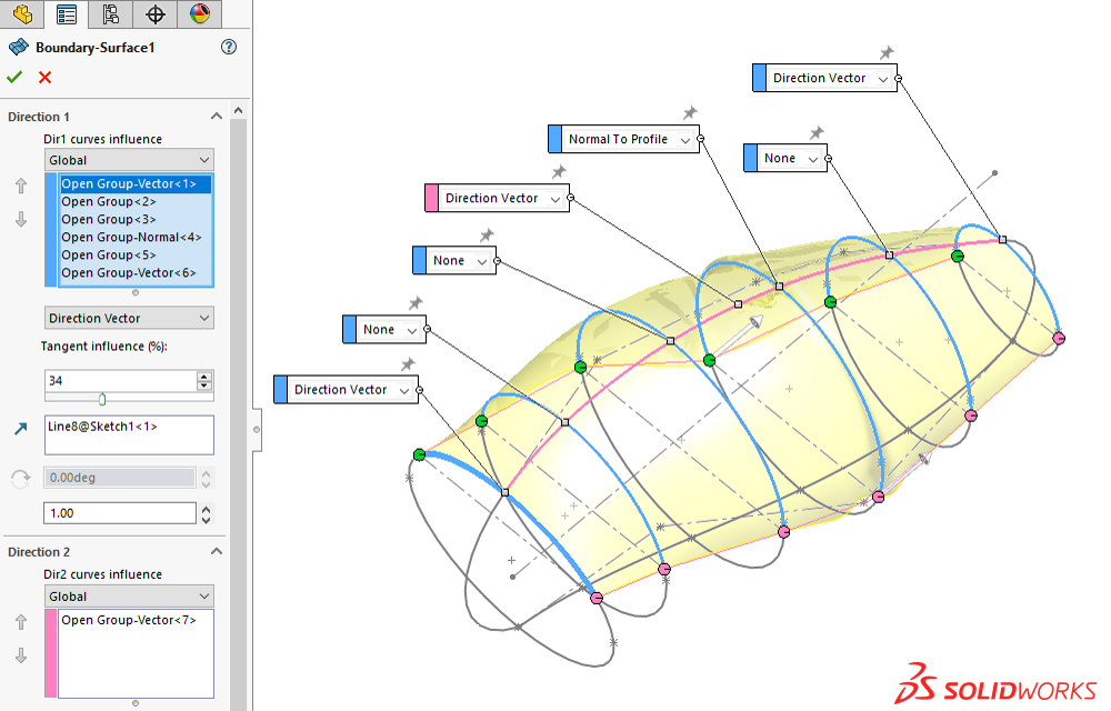
That high level of precision and control does come at a price though. While SOLIDWORKS can create highly complex surfaces, it can sometimes become tedious when working with highly organic, freeform shape — often due to the need for many parameters to define our design.
So, while we can achieve a high level of precision and accuracy with SOLIDWORKS surface modeling, the trade-off is the time and effort required to achieve it.
xShape Subdivision Modeling: Fluid and Flexible Control
Subdivision modeling in xShape focuses on creating smooth, organic forms with less emphasis on precision. The analogy of “digital clay” fits well here — just like molding real clay in our hands, we are generally more concerned with the overall form of our model than its precise dimensions.
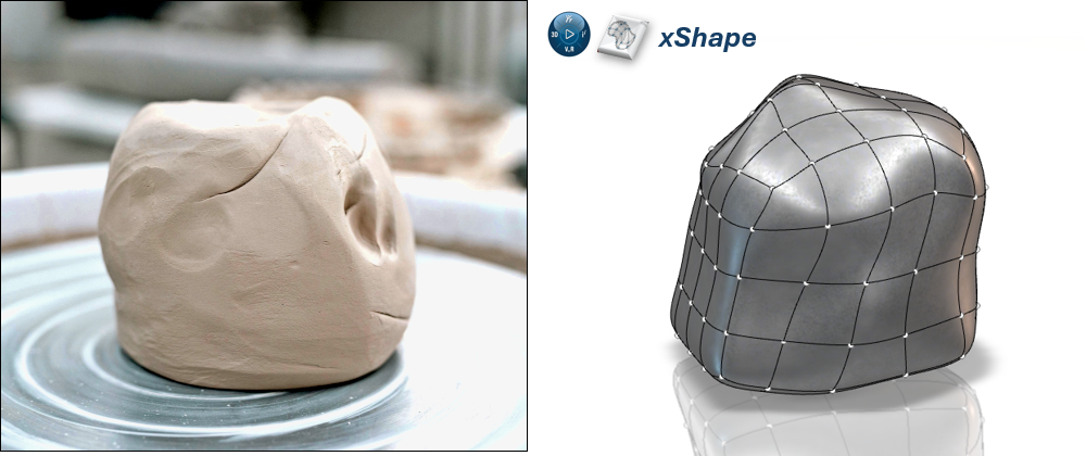
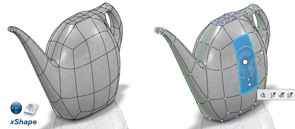
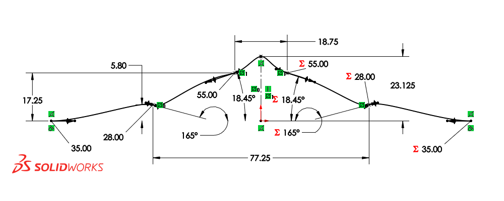
Defining the part shown below with surface features in SOLIDWORKS can be a cumbersome process. It’s a fairly complex shape that requires many parameters and a significant amount of time and effort to define.
But when modeled in xShape, the process is much more straightforward, as all we need to do is “push” and “pull” on our “digital clay” to achieve the desired geometry.
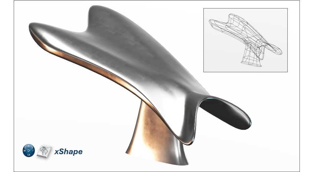
Defining the part shown below with surface features in SOLIDWORKS can be a cumbersome process. It’s a fairly complex shape that requires many parameters and a significant amount of time and effort to define.
But when modeled in xShape, the process is much more straightforward, as all we need to do is “push” and “pull” on our “digital clay” to achieve the desired geometry. But this also represents a trade-off — the lack of parametric constraints also means that xShape may not be suitable for designs where dimensional accuracy is a must.
So, while xShape is highly versatile for sculpting complex forms, it doesn’t offer the same level of precision and control that is typical of engineering design that SOLIDWORKS does.
Assessing User Interface and Ease of Use
SOLIDWORKS and xShape also have similar but different user interfaces — one uses a robust, traditional desktop interface while the other adopts a “design anywhere” cloud-based interface. Both tools are designed to be easy to navigate and use.
SOLIDWORKS: Traditional CAD Interface
SOLIDWORKS utilizes traditional CAD interfaces and workflows, which are designed to be intuitive and easy to learn but can feel somewhat rigid if we are new to CAD modeling.
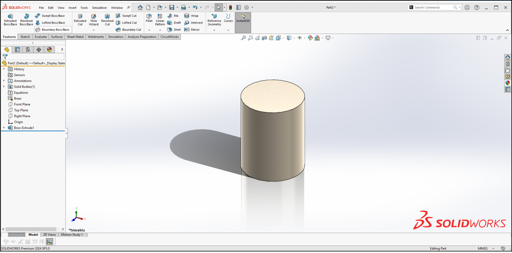
As a Windows-native program, most users will find its UI easy to navigate. The UI itself is designed around efficient modeling with a massive number of customizations and shortcuts available to speed up workflows.
This also includes a powerful search function that puts nearly any command, feature, or tool right at our fingertips.
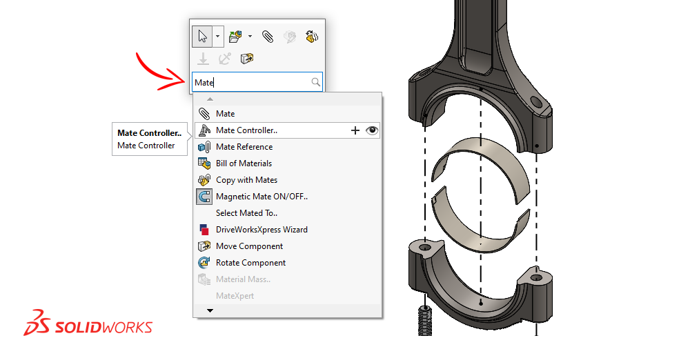
We can expect straightforward workflows for engineering design due to the parametric nature of SOLIDWORKS. It makes it easy to define the specific parameters (and their tolerances) that drive our designs.
Parametric modeling forces our models to be more “rigid” as those parameters lock our model into the form we’ve defined — which is a huge plus for most engineering design.
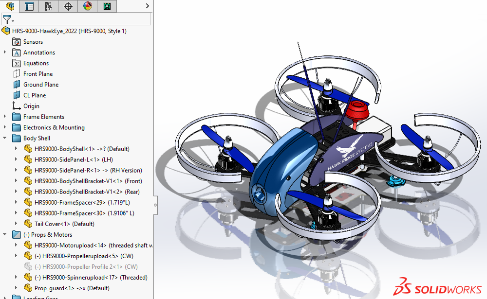
To be clear, when we say “rigid,” we don’t mean that we can’t change our designs easily in SOLIDWORKS, just that our models are held to our specific design parameters. Design changes simply require a change in parameters.
On the flip side, the “rigid” nature of this parametric design can make more complex geometry cumbersome to define. But when precision, accuracy, and repeatability are key design drivers, parametric modeling shines.
xShape: Cloud-Based Interface
xShape features a more artist-friendly interface with workflows that will seem more intuitive to those who lack experience with traditional CAD tools. Instead of a plethora of features and parameters, we have a much smaller set of tools focused on directly manipulating our geometry.
xShape automatically morphs and smooths our geometry based on our inputs, allowing us to quickly create organic shapes without being encumbered by a large number of parameters.
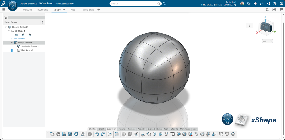
With subdivision modeling, we don’t always need to stick to a specific plan or strict set of requirements. There are certainly best practices to follow but because our model isn’t being driven by parameters, our models are far less “rigid.”
Changes to xShape models require less forethought as we don’t need to worry about feature history or dependencies between specific geometry like we do in SOLIDWORKS. Instead, we simply grab the geometry we want to manipulate and make the change.
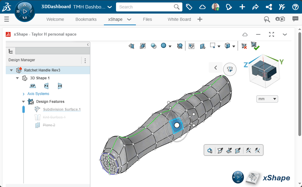
With subdivision modeling, we don’t always need to stick to a specific plan or strict set of requirements. There are certainly best practices to follow but because our model isn’t being driven by parameters, our models are far less “rigid.”
Changes to xShape models require less forethought as we don’t need to worry about feature history or dependencies between specific geometry like we do in SOLIDWORKS. Instead, we simply grab the geometry we want to manipulate and make the change. The nature of subdivision modeling tends to lack the precision and control that SOLIDWORKS offers, but that’s a necessary trade-off for certain applications.
For industrial designers, artists, and even engineers who prioritize speed and creative freedom over precise control, xShape’s interface is highly effective.
Understanding Applications and Use Cases
Every application is different, but the strengths of each tool should be coming into view. If we need precision and control, SOLIDWORKS is likely the answer. If our designs are more fluid and freeform, xShape has us covered.
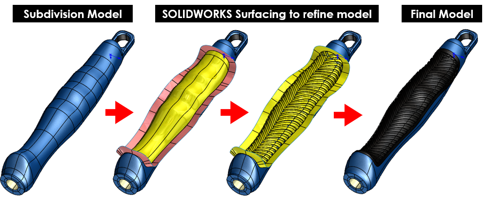
Each tool has unique strengths and applications where they fit best — and don’t forget that we can easily use them together, as necessary.
Best Use Cases for xShape Subdivision Surface Modeling
xShape shines for products or parts where aesthetic design and organic shapes are central themes of our design and development process, such as:
- Conceptual Design: For organic geometries where rapid iteration and sculpting of complex forms are essential for innovation.
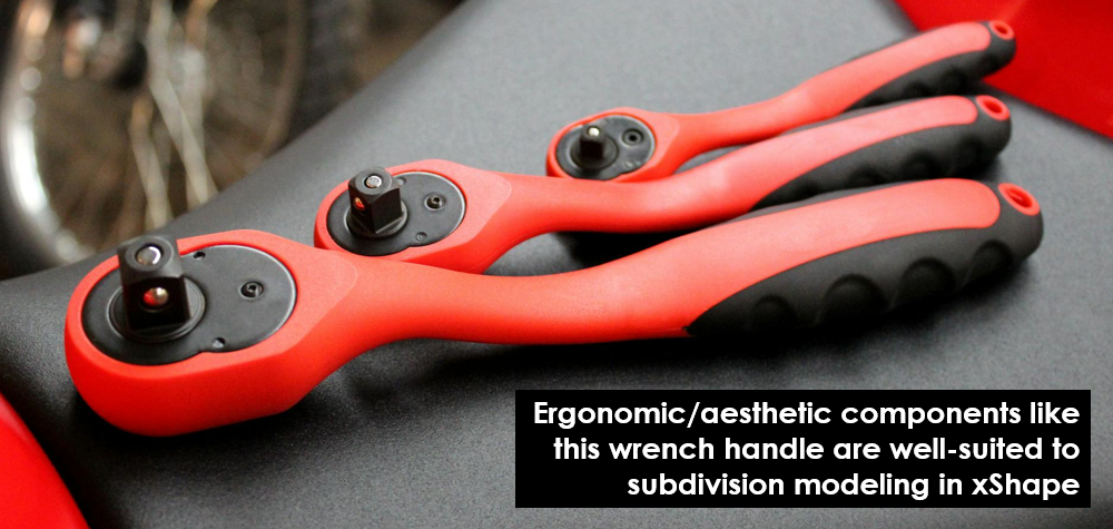
- Ergonomic Interfaces: Creating form-fitting, ergonomic shapes for consumer products and human interfaces, such as vehicle interiors, furniture, and ergonomic tool handles.
- Aesthetic Design: Parts where sleek form and aesthetic quality are a key design driver.
- Entertainment Industry and Visual Design: Modeling complex characters or props for films, games, animations, or graphic designs, such as logos and interactive models.
- Bio-Medical Modeling: Modeling of organic tissues and structures that aren’t well defined by mechanical parameters (often as a precursor to the design of medical devices or devices that interact with the human body).
Integration and Collaboration: Using Both Tools
SOLIDWORKS and xShape have been specifically developed for multi-user and multi-software environments. In fact, the entire suite of SOLIDWORKS Cloud tools on the 3DEXPERIENCE platform were designed from the ground up to be collaborative tools.
As such, working with either set of tools allows us a wide latitude for integrating them into our workflows and development processes.
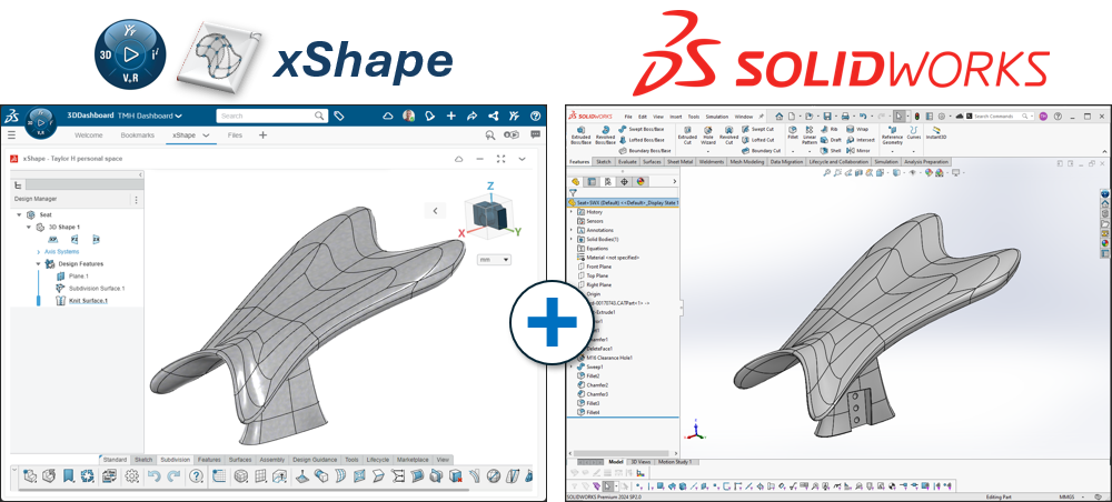
We can use both tools in tandem to take advantage of the strengths of both. Both tools integrate seamlessly with our data management systems (whether it be our local PDM servers or cloud-based data management), analysis workflows with SOLIDWORKS Simulation or 3DEXPERIENCE SIMULIA, manufacturing workflows with SOLIDWORKS CAM, CAMWorks, or the NC Shop Floor Programmer role within 3DEXPERIENCE DELMIA, and the list goes on…
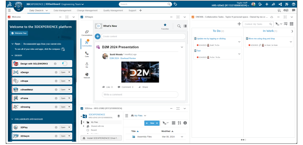
When it comes down to it, the focus on integration and collaboration means that modeling in either xShape or SOLIDWORKS (or, ideally, both!) can easily be integrated into nearly any workflow.
The Final Note
Both SOLIDWORKS 3D CAD and xShape as part of 3D Sculptor offer powerful modeling tools, but each utilizes a very different modeling methodology, both of which can be beneficial depending on our application.
SOLIDWORKS excels at parametric surface modeling for engineering precision and manufacturing design. xShape offers a more freeform approach with subdivision surface modeling, making it ideal for the design of smooth, organic geometries.
SOLIDWORKS versus xShape ultimately comes down to the nature of the project — whether you need precise engineering control or more artistic freedom.
For those working at the intersection of both, integrating each tool into our workflows can provide the best of both worlds.
As always, we are here to help be part of the solution to your design and engineering challenges. Contact us at Hawk Ridge Systems to discuss how the suite of SOLIDWORKS software can help improve your designs and workflows.
