SOLIDWORKS Simulation
Accurately test and analyze your designs against real-world conditions — at any point in your design process.
Get Pricing Sent to You Today
While you are waiting, check out our Resource Center or read our Blog!

Finite Element Analysis (FEA) Software Integrated with SOLIDWORKS
Predict potential design issues early, feel confident your product will perform the way it’s supposed to, and reduce the amount of prototypes and physical testing you need as you virtually test against real-world conditions.
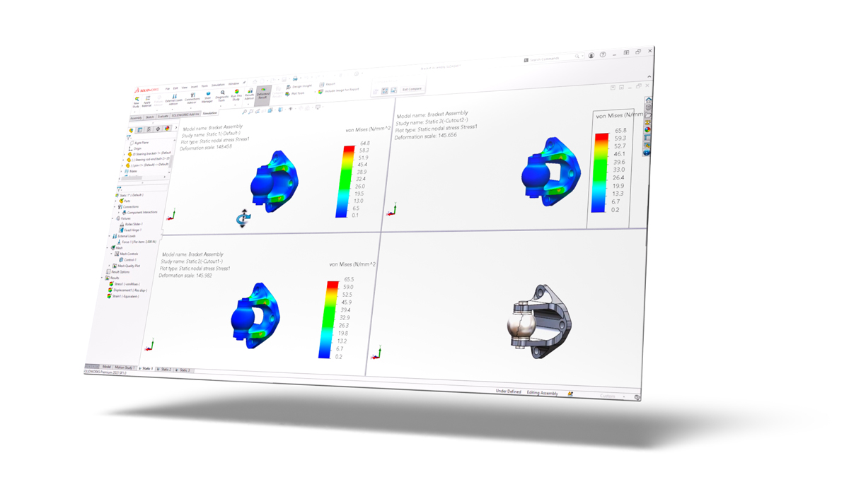
SOLIDWORKS Simulation provides you with a powerful and easy-to-use virtual environment, using finite element solvers where you can test, analyze, and change your product designs — directly within your SOLIDWORKS 3D CAD interface.
Its analysis tools include a variety of rigorous FEA studies like linear, nonlinear, thermal, motion, fatigue, and more, so you can stress test, drop test, and check for factor of safety (FOS) during your design process.
Not sure how much Simulation could save you?
Use our Simulation ROI Calculator to estimate savings from fewer prototypes, reduced scrap, and faster design cycles — in just a few minutes.
-
Fully Integrated Analysis
SOLIDWORKS Simulation is fully integrated into the SOLIDWORKS 3D CAD environment leveraging common features like configurations to allow for testing of different design iterations.
-
Validation Tutorials and Benchmark Examples
SOLIDWORKS Simulation come stocked with a multitude of examples to familiarize yourself with the common features and to ensure confidence that it can provide valid results.
-
Meshing Controls
There are 3 mesh element types: solids, shells, and beams. Each is used to ensure accuracy in your results but also to help solve the analysis with its greatest efficiency. Mesh controls are also available to help narrow down the scope in areas of concern for added accuracy.
-
Body Interactions
There are a variety of different body interactions available that include:
- Bonded
- Contact (formally known as “no penetration”)
- Free (formally known as “allow penetration”)
- Shrink fit
- Virtual wall
- Self contact
-
Virtual Connectors
To decrease solve time, manual creation of virtual connectors to replace physical bodies include:
- Bolt
- Pin
- Spring
- Bearing
- Elastic support
- Self contact
-
Body Restraints
A variety of fixture options to control the degrees of freedom of every body to reflect most accurately how the real-life scenario is restrained.
-
Loads and Prescribed Displacements
Load options include:
- Force
- Pressure
- Torque
- Gravity
- Virtual remote loads
- Temperature
- Prescribed displacements
- Import of pressures and temperatures from SOLIDWORKS Flow Simulation
- Import of thermal study temperatures from Simulation Professional
-
Communication and Reporting
SOLIDWORKS Simulation has embedded templates to output analysis reports that include details of the study setup and images of the results. Analysis results can also be shared using eDrawings.
-
Linear Static Analysis for Parts and Assemblies
Check for stress, strain, displacement, and factor of safety (FOS) under linear assumptions. These include:
- Small displacements
- Load is applied slowly and gradually
- Response is proportional to the load
- Material behaves linear elastically
- No permanent deformation
-
Stress Hot Spot Diagnostics
Check for irregular stress gradients to pinpoint stress singularities.
-
Fatigue Analysis
By referencing the baseline structural analysis, this study assumes high-cycle fatigue and uses S/N material data to output life cycles and cumulative damage.
-
Time-Based Motion
Intended for moving mechanisms, this rigid body kinematic and dynamic motion tool allows you to gain insight on velocities, accelerations, torque, and overall movement under different load and motor conditions.
-
Trend Tracker
Track your study design iterations of a static study and view the trend of desired result outputs.
-
Buckling Analysis
Calculate the buckling load factor on tall and slender bodies to determine how much more load your structure can take before buckling.
-
Drop Test Analysis
Determine the stress and displacement effects of your design upon impact on a rigid or flexible virtual surface.
-
Parametric and Topology Design Optimization
Automate the process to find the optimal design combination by varying dimensional and FEA based parameters while adhering to design constraints and reducing the overall mass. Topology optimization determines a unique shape alternative to help reduce the mass while following design and manufacturing constraints.
-
Pressure Vessel Analysis
Using the methodologies of ASME International Boiler and Pressure Vessel Code ASME BPVC-VIII-2, this study combines baseline static studies using linear combination or the square root of the sum of squares (SRSS).
-
Event-Based Motion Analysis
Similar to time-based motion, this replaces the control of different sequences based on time with event-triggered motion controls by incorporating different combinations of sensors.
-
Frequency Analysis
This study determines both the modal shape and natural frequencies of parts and assemblies. This information is critical when designing products that will be subjected to vibration in their working environment.
-
Thermal Analysis
This study uses an FEA approach to determine the temperature of bodies excluding the effects of moving air. Options include steady-state and transient effects.
-
Submodeling
Increase the resolution of results in a subset of parts that references and transfers the boundary conditions from a top-level assembly.
-
Load Case Manager
View the effects of different load combinations on your designs.
-
2D Simplification
Reduce the size of the problem and calculation times by converting the 3D shape to a 2D plane stress, plane strain, or axi-symmetric condition.
-
Automated Toolbox Fasteners Conversion to Virtual Bolts
SOLIDWORKS Simulation includes Toolbox integration features to automatically convert physical hardware to virtual components.
-
Linear Dynamic Studies
Building upon the frequency study, calculate the stresses and displacements due to forcing vibrations and calculate the response of dynamic and shock loading for linear elastic materials. These study types include:
- Modal time history analysis
- Harmonic analysis
- Random vibration analysis
- Response spectrum analysis
-
Nonlinear Analysis
Nonlinear analysis lets you analyze complex material behavior, such as post-yield metals, rubbers, and plastics, as well as to account for large deflections and sliding contact.
-
Composite Material
Define the material properties and orientation of composite laminates.
Cutting Design Time by Weeks: Forgeline Motorsports
Watch and delve into the fascinating journey of how Forgeline Motorsports successfully decreased their time to market from an entire month down to just a few hours.
Gain valuable insights into their innovative approach, which involves harnessing the power of SOLIDWORKS Simulation and making strategic use of Hawk Ridge Systems’ comprehensive services.
Simulation Resources
Success Story: Up for the Challenge
Watch Video
SOLIDWORKS Simulation Buyer's Guide
Download Guide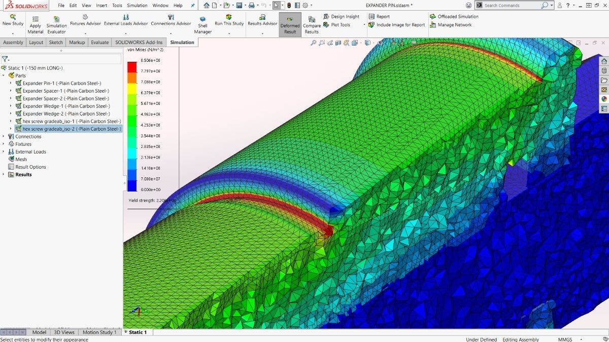
Predict Your Design’s Real-World Behaviors
Watch Video
Drive the Design Creation Process With Simulation
Download GuideFrequently Asked Questions
Yes. Simulation is integrated into the SOLIDWORKS interface, making it easy to learn by being in the familiar CAD environment. This allows for quick and easy testing of different design iterations and getting results to make better design decisions.
Yes. Like SOLIDWORKS CAD, Simulation is broken into 3 levels: Standard, Professional, and Premium. Each is a stepping stone to include unique study types to allow testing of different modes of failure. These include but are not limited to static, nonlinear, vibration, buckling, and drop tests. For more information, take a look at the Simulation Buyers Guide.
SOLIDWORKS Simulation is one of the leading finite element analysis (FEA) software offerings in the industry. Simulation is embedded with many real-world validation and benchmark examples showcasing how close results come to traditional hand calculations. One Hawk Ridge Systems Customer, Forgeline Motorsports, was able to predict accuracy to 99.5% compared to how a part performs in a real physical test.
Yes. SOLIDWORKS Simulation has options to be purchased as a perpetual license or term. Term licenses are offered for 3 months or 1 year. Hawk Ridge Technical Support can also be purchased with term licensing.
Yes. Hawk Ridge Systems offers great Simulation training options and bundles that are taught by experienced, degreed engineers and designed to get you up-to-speed with the software quickly.
Services & Customer Benefits
Technical Support
The simulation experts on our technical team are available to assist with all your analysis questions and software troubleshooting, whether it’s a quick tech support call or an in-depth ‘Ask-an-Expert’ session.
Simulation Training
Professional Services
Leverage the expertise of our simulation team through consulting on your next project. We can assist you in developing your strategy and analysis approach to ensure the accuracy of your results.