
For most mold designs, we split the mold tooling into two halves: a core side and a cavity side. However, splitting the tooling into three or more pieces works better for some designs.
While this functionality is unavailable in the normal tooling split command in SOLIDWORKS (you can only use one continuous parting surface), we can still achieve it with a few extra steps. Because this is a more advanced mold-making technique, this blog will assume you are already familiar with the standard mold design process in SOLIDWORKS.
Method 1: Continuing with Mold Design Tools
This method uses the typical mold design tools to create a tooling split of the core and cavity. Then, you can further split the core or the cavity (or both) to create extra tooling. You can accomplish this most easily by creating a surface and then using the split command.
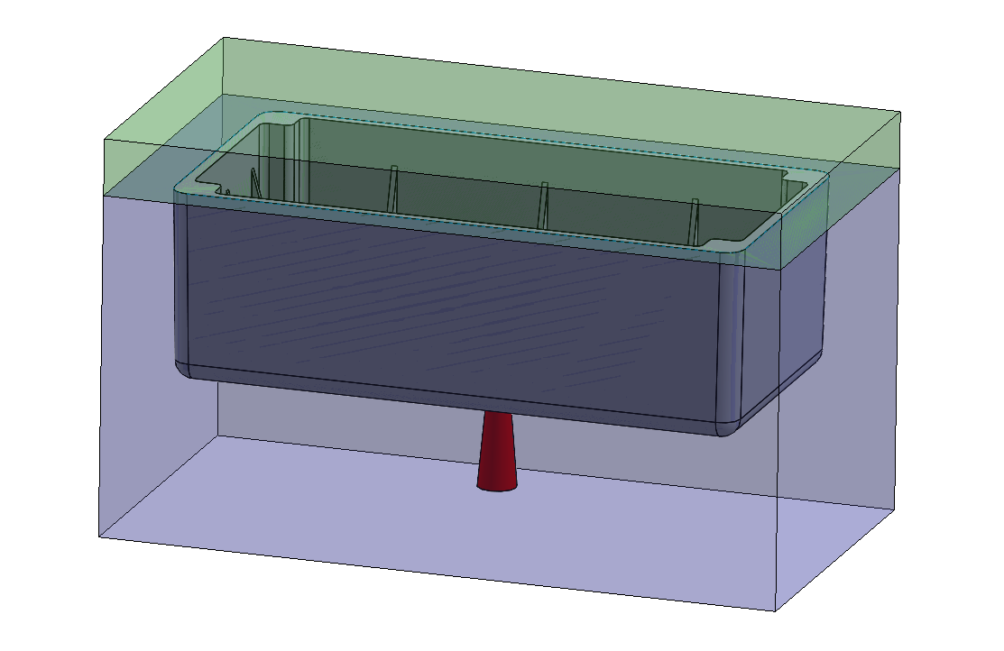
First, offset a surface from the bottom of the molded part and extend it until the surface is larger than the existing tooling. This will separate the runner geometry into a new tooling block.
Then, use the split command to cut the mold body into two separate bodies with the newly created surface.
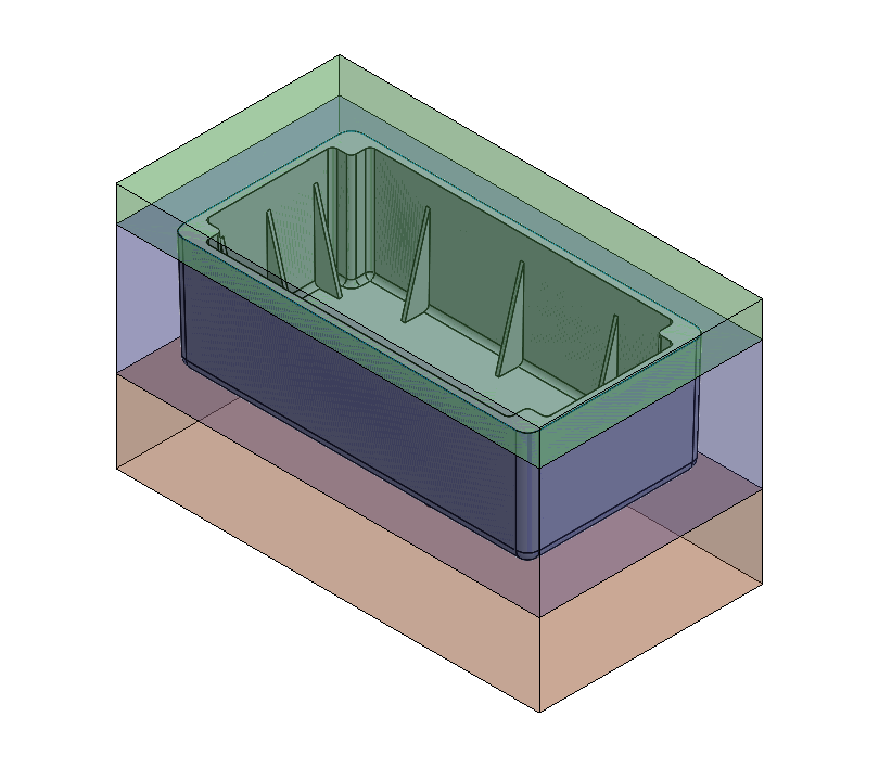
This results in three separate tooling bodies that you can insert into the larger mold assembly to manufacture the part and its attached runner.
Method 2: Using Surfacing Techniques
Sometimes, it’s simpler to forego the normal tooling split command and use manual surfacing techniques. This can be useful for more complex parts where the standard mold commands may not work well or at all. It can also be helpful if you are already familiar with the surfacing workflow and don’t want to use the mold commands in SOLIDWORKS.
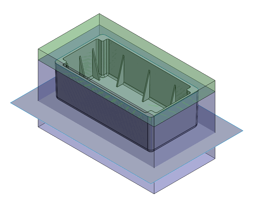
To get started, make a ruled surface around the top edge of the box, perpendicular to the direction of the pull.
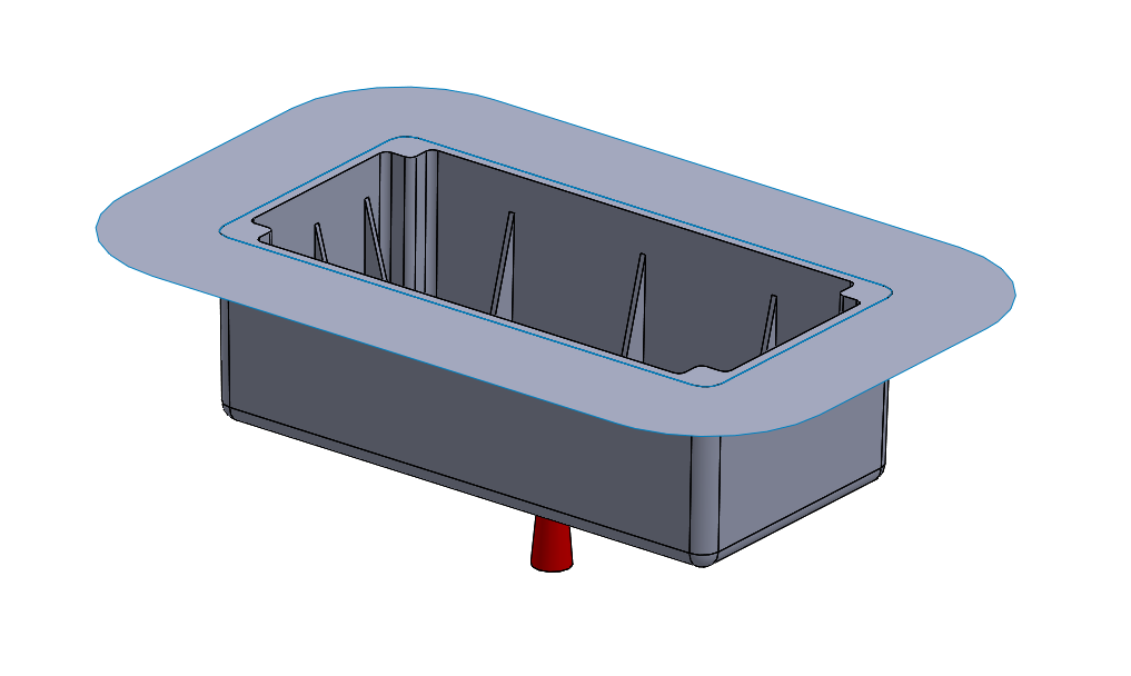
Next, construct a secondary parting surface. This is simply offset from the bottom of the molded part and then extended in all directions. In other words, you can make it in the same way as the first method.
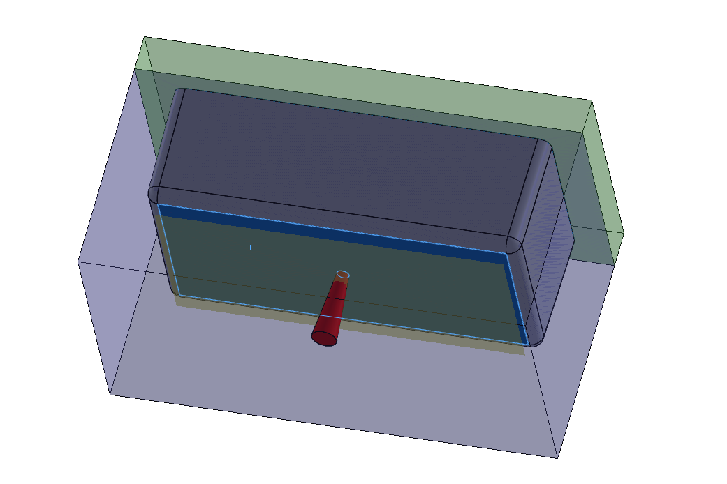
Using an extrude, make a solid body around the molded part. In this case, the mold tooling will be rectangular but can be any shape. The merge result checkbox is cleared to leave the extrude as a separate solid body.
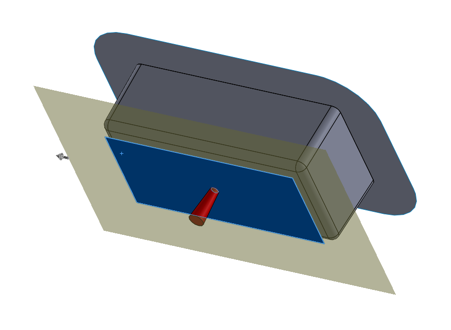
Next, hollow out the mold tooling body with the Combine command using the subtract option.
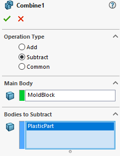
Figure 10: The plastic part is subtracted from the mold block to create a cavity. Note that this will consume the part body.
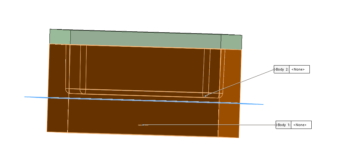
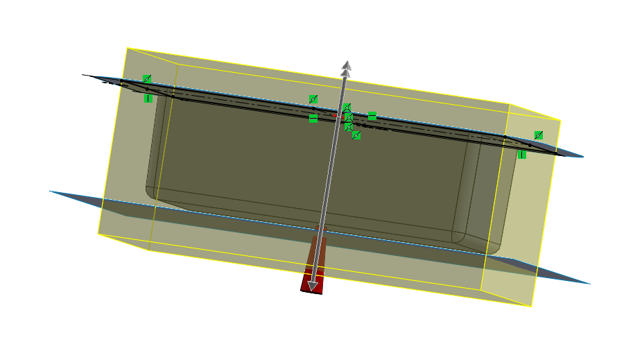
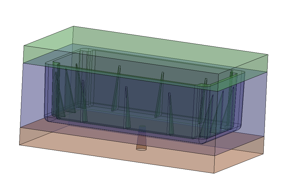
Then, apply the Split command to split the tooling into three separate bodies, using both surfaces created earlier (the ruled surface and offset surface).
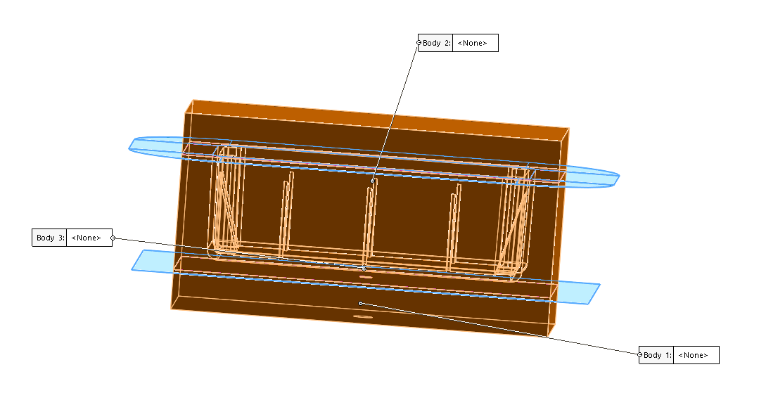
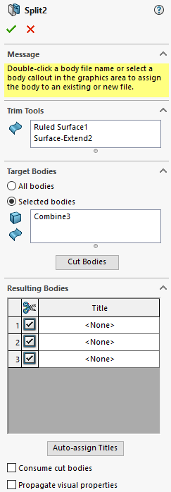
Figure 12: The two surfaces are used to split the mold tooling body.
While the two surfaces were created here using a Ruled Surface and Offset Surface command, you could use any surfacing techniques. In addition, you could use any number of surfaces to generate more independent mold bodies.
Choosing the Right Technique for Mold Splitting
Either one of these techniques would allow the creation of a mold with three or more bodies. They both differ from the Core command in the Mold Tools because they are based on surfaces instead of sketches. Therefore, the Core command is typically better for removing smaller sections of the mold, while these techniques are better for splitting the mold entirely into large equal sections.
One notable difference between the first and second methods shown here is that the first uses the conventional Tooling Split command. This means the runner cannot pass outside the mold, and you’d need to create a hole afterwards. The second uses purely surfacing commands so the runner can immediately penetrate the outside of the tooling.
The first technique can be helpful for users already familiar with the mold-making commands in SOLIDWORKS or for models originally designed with two mold halves that need to later be divided further into more individual tooling blocks.
The second technique may be better for more complex ground-up designs, as the surfacing commands generally offer a finer level of control.
Have questions? Contact us today or check out some of our other mold making tutorial blogs, including topics such as the Parting Surface command, Parting Line command and the Shut-Off Surface command.