SOLIDWORKS Desktop has long been the go-to tool for CAD modeling in the world of engineering and design. In the age of cloud computing and collaboration, we now also have SOLIDWORKS cloud-based apps on the 3DEXPERIENCE platform. Both are well-known in the world of engineering and design. But what many people don’t know is that SOLIDWORKS Desktop and the Apps on the 3DEXPERIENCE platform are designed to work hand-in-hand. In fact, they are really just two different facets of the same ecosystem — and Hawk Ridge Systems is here to support both!
To demonstrate this, this blog will focus on using SOLIDWORKS Desktop in tandem with the 3DEXPERIENCE CAD App, xShape. xShape functions very differently than the parametric modeling tools we are used to in SOLIDWORKS, and as such, it has very different strengths. In this blog, we will utilize the strengths of both to show how we can build more robust designs.
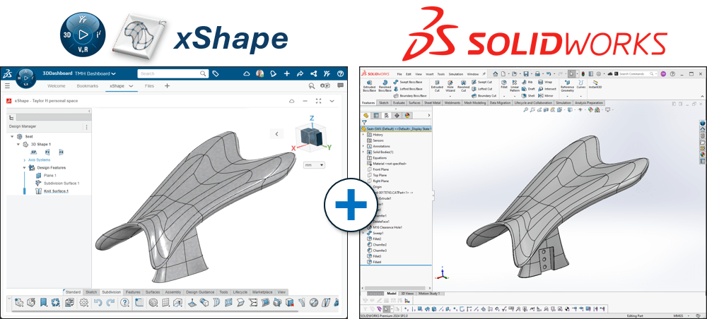
3DEXPERIENCE Cloud CAD – Sub-D Modeling with xShape
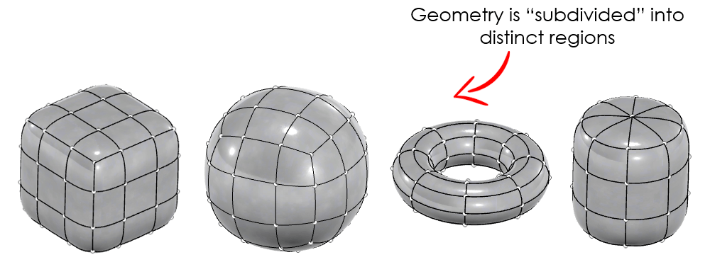
xShape is a part of the 3D Sculptor role on the 3DEXPERIENCE platform. xShape is a subdivision (often abbreviated as “sub-D”) modeling tool, which many SOLIDWORKS users may not be familiar with. Subdivision modeling is described in detail in another blog, but the core concept is to subdivide geometry into distinct regions or divisions—hence the name “subdivision”. We then directly manipulate those regions by “pushing” and “pulling” directly on those regions of our model’s geometry.
If you’re new to xShape or sub-D modeling, check out our related content to get up to speed:
- Subdivision Modeling Made Easy Using 3DSculptor
- 6 Tips and Tricks for Sub-D Modeling in 3DEXPERIENCE xShape
Be sure check out our brief video on all of the Cloud CAD tools 3DEXPERIENCE Cloud CAD – Revolutionary Design Suite for an overview of what they can do as well.
We should note, that while this post focuses on integration between xShape and SOLIDWORKS Desktop, the entire suite of 3DEXPERIENCE Apps is designed to work with almost any CAD software. No matter which CAD package you prefer, you can make use of the subdivision modeling in xShape to give more fidelity to your designs.
SOLIDWORKS and xShape — What are their Strengths?
SOLIDWORKS — Parametric Modeling
SOLIDWORKS Desktop is a parametric modeling tool. That means we use specific parameters (hence the name “parametric”) to define our designs. This includes things like sketch geometry, dimensions, relations, features, mates, etc. Each one can be considered a parameter of our design — the elements we define to build our geometry. It’s something almost all SOLIDWORKS users are innately familiar with.
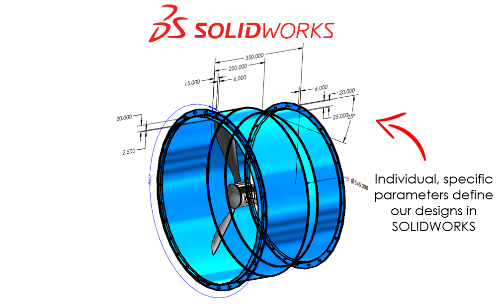
This type of modeling is perfect for parts that have specific requirements related to their form, fit, and function. We can define precise dimensions, shapes, relations, etc., very easily with parametric design. And because parametric design information is stored within the model in SOLIDWORKS, making changes to our models is as straightforward as modifying our parameters.
The 3DEXPERIENCE platform also has a cloud-based parametric modeling tool called xDesign (part of the 3D Creator role) that can be used on any internet-connected device. Our video, 3DEXPERIENCE Cloud CAD: Browser-Based Mechanical Design, gives a good overview if you’re interested in learning more.
xShape — Sub-D Modeling
xShape is a subdivision (Sub-D) modeling tool. That means that we don’t define specific parameters to control our designs. Instead, sub-D modeling is more freeform. It’s akin to modeling with “digital clay.”
We start out with basic shapes, called “primitives”, and then “push” and “pull” on that shape to form our designs. You can learn more about primitives in our tips and tricks blog post for xShape. Once we pick a primitive, there are no individual features or dimensions that constrain our design. To make changes to any part of our model, we directly mold our geometry just as we would a piece of clay in our hands.
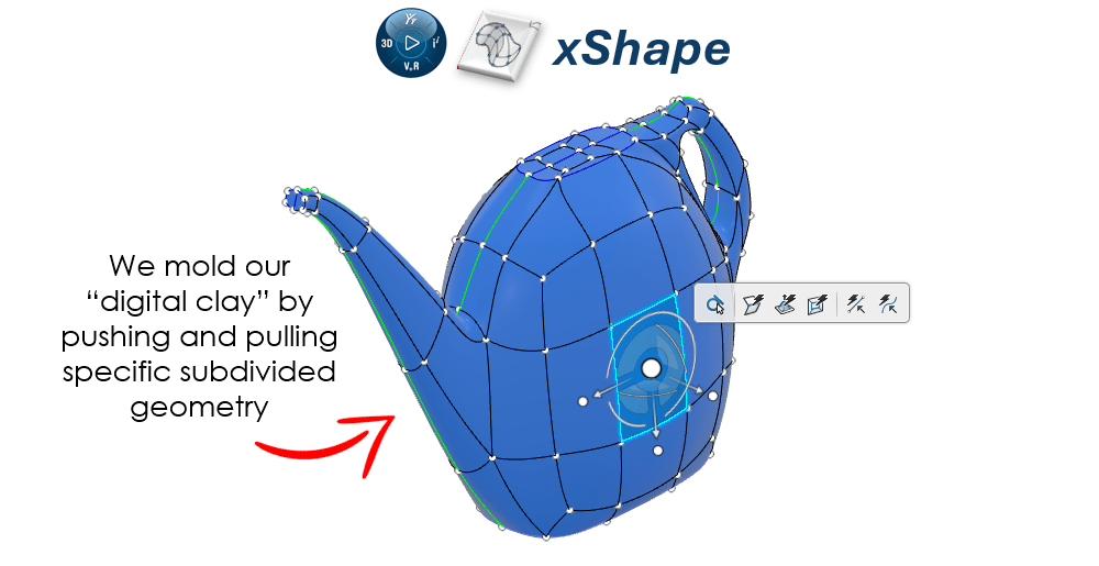
As a result, creating organic, freeform designs with sub-D modeling in xShape is a breeze.
Utilizing Both Tools to Their Strengths
Being able to create freeform designs is all well and good, but often those designs need to interface with or assemble to mechanical parts. And as we all know, mechanical design is SOLIDWORKS bread and butter. So, if our designs require both mechanical geometry as well as free-form, organic geometry, that begs the question: Why not use both tools to their strengths?
Thankfully, the integrated nature of the SOLIDWORKS family of tools and the 3DEXPERIENCE platform allows us to do just that.
Case Study: Using SOLIDWORKS and xShape Together
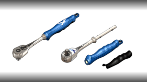
Designing an Ergonomic Socket Wrench
A hand tool is a great use case for marrying the benefits of both SOLIDWORKS Desktop and xShape to create a more robust design. There are certain aspects of a hand tool that are well suited to parametric modeling, such as the working end of the tool. And there are other aspects that are better suited for subdivision modeling, such as an ergonomic handle.
Therefore, to demonstrate this we will investigate just such a case study with the design of an ergonomic ratcheting socket wrench.
Design Considerations
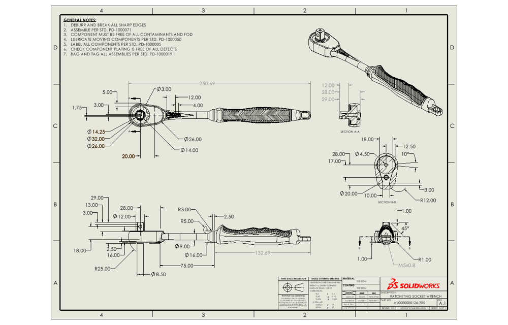
Let’s say that we are tasked with designing a medium-sized ratcheting socket wrench with a 3/8” square drive, direction selector, and an ergonomic (and visually appealing) handle.
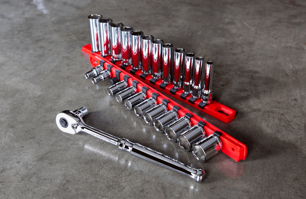
A 3/8” square drive has well-defined dimensions and specifications. Our design must fit tight specifications so that it can correctly interface with standard 3/8” square drive sockets. On the other hand, the ergonomic handle has much looser requirements. It really just needs to fit the average person’s hand and be visually appealing. As such, we will design different elements of the wrench utilizing the best tool for the job: SOLIDWORKS Desktop for the mechanical (parametric) elements and xShape for the ergonomic (subdivision) elements.
Parametric Elements
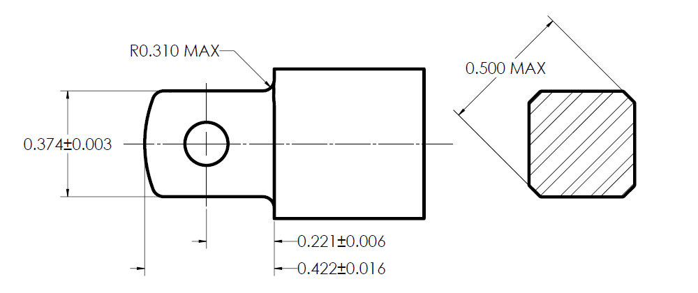
Standards such as ANSI/ASME B107.1-2002, “Socket Wrenches, Hand (Inch Series)” or references such as the “Machinery’s Handbook” give requirements for standard socket wrenches. We will design our square drive according to these well-defined requirements.
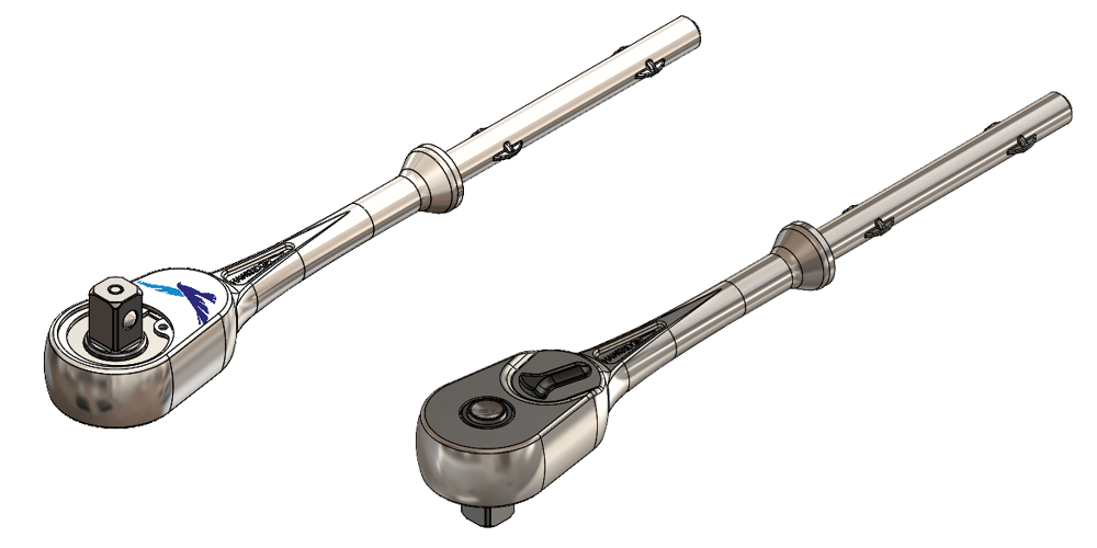
We also must consider the mechanisms that allow a ratcheting wrench to work. The pawl, gear/wheel, springs, detent, direction selector, etc., are all mechanical components that must act in harmony to have a working wrench. There might also be design considerations on size, strength, clearance, packaging, etc. Each of these considerations translates directly into specific parameters and mechanical requirements that dictate a large part of our design. As such, they will flow right into the definition of our parametric CAD model.
Subdivision Elements
The ergonomic grip on the other hand doesn’t have many hard parameters or mechanical requirements. It just needs to fit the average person’s hand comfortably, be visually appealing, and integrate with the mechanical (parametric) elements of the wrench.
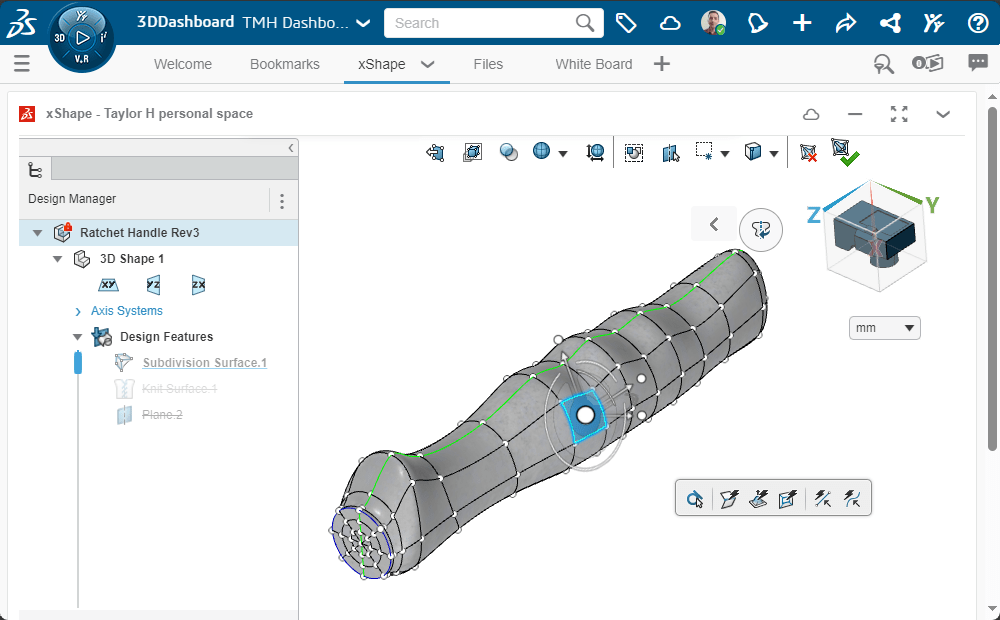
Of course, it must also be strong enough to stand up to reasonable use, be manufacturable, etc. —but that’s subject all its own involving simulation, testing, and validation. If you want to learn more about Simulation and part validation, check out on content on the Road to Validation with SOLIDWORKS Simulation.
Why Not Design the Handle in SOLIDWORKS as Well?
We can also create smooth, organic geometry in SOLIDWORKS. The handle certainly could be modeled parametrically with Lofts, Boundaries, surfacing techniques, etc. But when it comes to creating ergonomic, freeform shapes, modeling parts parametrically may not be so easy.
SOLIDWORKS geometry will always be defined by specific parameters. As a result, SOLIDWORKS features can be easier to make more “precise” but can also be more challenging to manage. If you’ve ever modeled complex shapes organic shapes in SOLIDWORKS, you know it can sometimes take a fair amount of tweaking to get the shape “just right”.
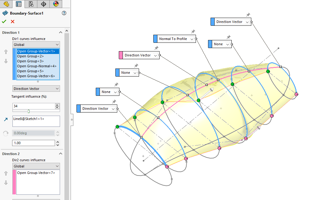
XShape, on the other hand, makes the creation of that same geometry very straightforward. As such, it allows us to meet our requirements without reducing design flexibility. Our “digital clay” in xShape lets us freely shape our handle geometry without being encumbered by a large number of parameters.
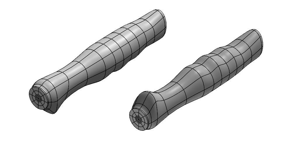
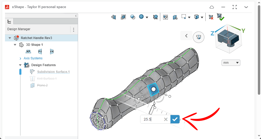
Now, this doesn’t mean xShape can’t be precise. It simply means that our geometry isn’t constrained by parameters like they are in SOLIDWORKS. To improve precision in xShape we can use reference images or concept sketches directly in our sub-d models to refine and guide our designs. See our Getting Started with xShape and Sub-D Modeling – Tips and Tricks blog post for more.
We can include parametric geometry from SOLIDWORKS or xDesign to help designs as well. We can even use exact values for how much we want to “push” and “pull” our geometry when forming it in xShape.
Combing Parametric Elements with Subdivision Elements
Now that we have our parametric design elements and our subdivision design elements, how do we bring them together?
The answer is straightforward. Thanks to the 3DEXPERIENCE platform and the interconnectivity between the SOLIDWORKS family of tools, we can easily use xShape models in SOLIDWORKS and vice versa.

For our case study, we can open our wrench handle in SOLIDWORKS Desktop via the 3DEXPERIENCE Connector (Collaborative Designer for SOLIDWORKS). This connector allows us to access the Cloud-based product data management (PDM) tools to directly pull our xShape part into SOLIDWORKS.
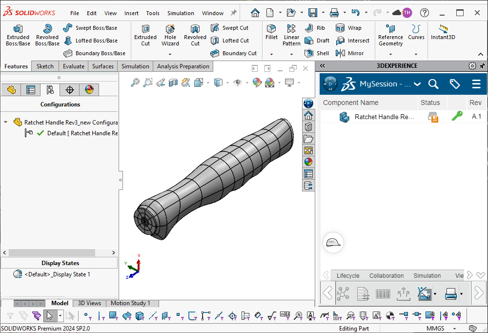
We intend the wrench handle to be over-molded onto the wrench body for this case study. We have pre-defined the wrench body side of the interface parametrically in SOLIDWORKS.
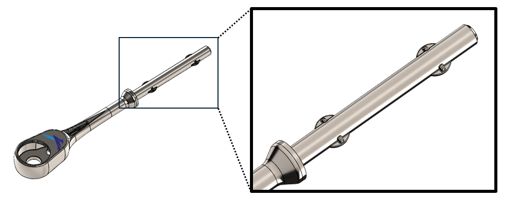
To match that interface on our sub-D handle model, we can use the existing parametric wrench body itself. One way to do this is by using the “Insert Part” command in SOLIDWORKS to bring the wrench body geometry into our handle model. Then using the “Subtract” option of the “Combine” feature we can transfer the parametric interface information directly to our handle model. The result is a perfectly matched interface between wrench body and handle.
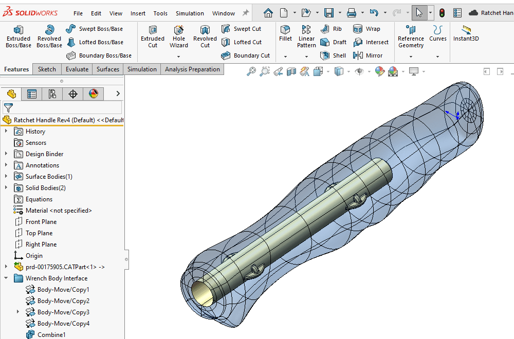
In practice, we would include some analysis of the over-molding process to account for things like shrinkage of the materials during manufacture. That’s beyond the scope of this blog post, so we’ll assume that our geometry is okay. If you’re interested in that kind of analysis, SOLIDWORKS Plastics is built for just that — which you can learn about here: SOLIDWORKS Plastics Overview.
Editing xShape Subdivision Models with SOLIDWORKS
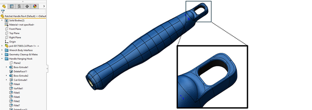
One of the great things about bringing xShape models into SOLIDWORKS Desktop is that just like any other solid, we are free to further modify them using parametric features. In this case we use Extrudes, Cuts, and Fillets to create a loop so that the wrench can be hung up when not in use.
We will also use our Surfacing tools along with some additional Extrudes, Cuts, and Patterns to create a form fitting grip. In this case we’ll model it as a separate body so that the main handle and the rubberized grip can be manufactured with two separate materials — stay tuned for a follow up blog post on this process as well!
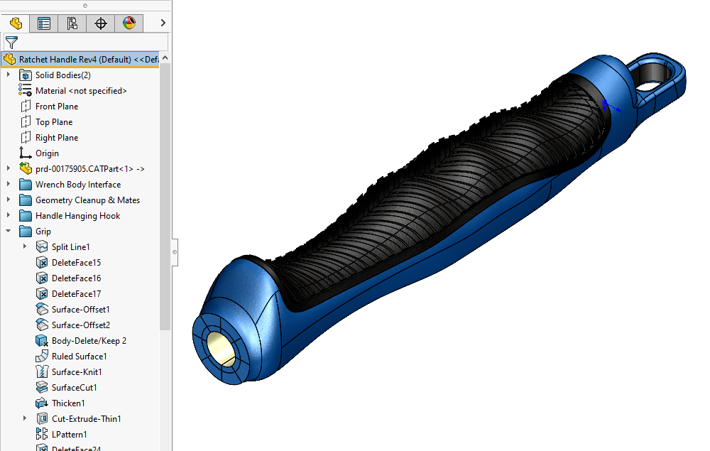
The bottom line is, regardless of the changes we need to make to our subdivision models, SOLIDWORKS has us covered. The interconnectivity of the SOLIDWORKS family of tools and the 3DEXPERIENCE platform give us a wide range of capabilities to realize our design.
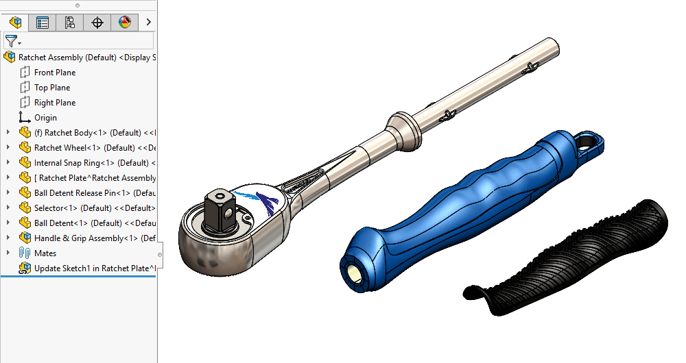
SOLIDWORKS Desktop & xShape: Use the Strengths of Both!
When we need to model mechanical, rigid geometry defined with strict parameters, SOLIDWORKS undoubtedly will be our workhorse. And when we need smooth, freeform geometry, xShape fits the bill.
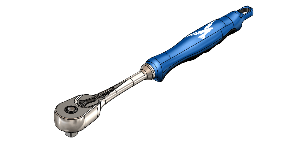
The fully integrated nature of SOLIDWORKS Desktop and xShape (along with all of the other 3DEXPERIENCE apps and roles) makes designing with both easy and straight-forward.
If you want to learn more about SOLIDWORKS Desktop, the xShape app/3D Sculptor role (or about the 3DEXPERIENCE apps in general), feel free to reach out!
Contact us any time to learn more about these tools and how they can be a part of the solution to your engineering and design challenges.
