Top 10 Expert SOLIDWORKS Surfacing Techniques
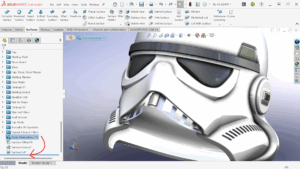
If you’ve ever tackled a complex surface model in SOLIDWORKS, you know how quickly the feature tree can spiral out of control. That’s exactly what happened when I set out to model a fully surfaced Stormtrooper helmet. It was a nerdy challenge, and the perfect way to dig deep into surfacing workflows and come out the other side with some valuable lessons.
This blog is a companion to the livestream presentation where we walked through ten expert techniques I used while building this helmet. Whether you’re working in industrial design, automotive, or just looking to sharpen your skills, these tips can help you build cleaner, more flexible, and more efficient surfacing models.
The ten tips we’ll cover:
- Create Reference Planes Using Vertices
- Extend Solid Geometry with Surface Offset
- Clean Up with Delete Body
- Loft with Tangency to Face
- Sacrificial Surfaces + Surface Fill
- Control Loft Curvature with ‘Normal to Profile’
- Planar Surface for Sketching
- Use “Keep Selections” in Surface Trim
- Flip Edge Direction in Ruled Surface
- Delete Face with Fill for Cleanup
1. Create Reference Planes Using Vertices
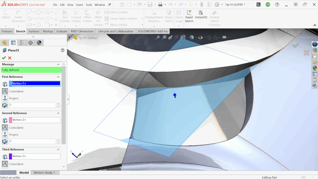
When building geometry off angled surfaces, try using three existing vertices to define a plane, then offset it for sketching. It’s a powerful way to avoid messy 3D sketches. And if you don’t have good vertices to work with, reference geometry points are just as effective, and they stand out in the feature tree for easy reuse later.
2. Extend Solid Geometry Using Surface Offset
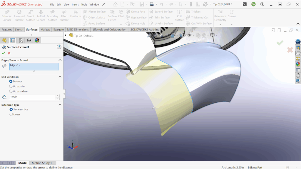
You can’t extend a solid face directly with surface tools, but you can cheat it. A surface offset with zero thickness creates a copy of the face as a surface. From there, Extended Surface gives you full control. From there, the new surface can be trimmed and then thickened to merge with the original body.
3. Clean Up with Delete Body

As your surfacing model evolves, you’ll inevitably create temporary surface bodies, tooling surfaces, offset references, and extra solids. Instead of adding a new Delete Body every time, I recommend a better approach: Create just one Delete Body feature and continuously bump it down the feature tree. This lets you clean up unnecessary geometry at every stage without bloating your feature list.
4. Loft with Tangency to Face for Ballooned Surfaces
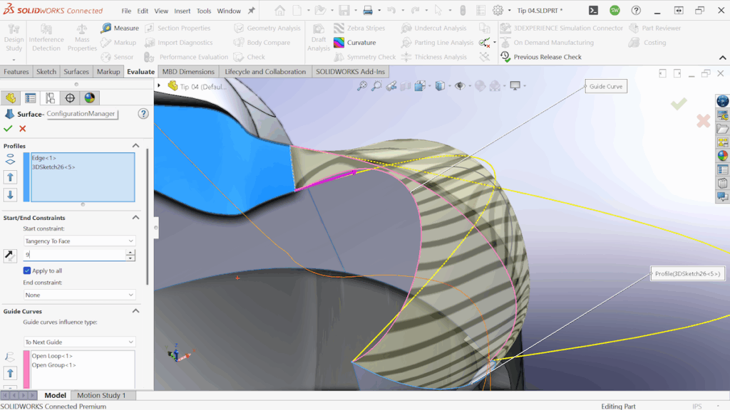
This is a great example of using Surface Loft with Tangency to Face to create smooth, intentional transitions. In this case, I needed the breather on the front of the helmet to balloon outward in a controlled way.
Instead of relying on complex guide curves or multiple profiles, I used the tangency control to push the shape outward.
Key Takeaway: You can increase the influence of the tangency setting to control how much the surface “balloons” away from the starting face.
There’s no guide curve down the middle (just two on the sides). By adjusting the tangency influence, I achieved exactly the shape I was after with minimal features.
5. Sacrificial Surfaces + Surface Fill = Magic
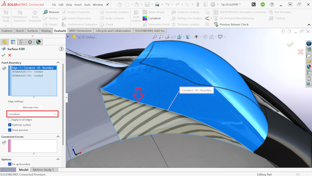
This tip technically comes before Tip 4 in the modeling process, but I’m bringing it up now because it both makes Tip 4 possible and also relies on Tip 4 to be completed.
To loft the breather outward in Tip 4, I first needed a surface at the bottom to serve as a reference edge. That surface didn’t exist yet, so I created a triangular sacrificial surface just to make the loft possible.
Once that loft was finished, I no longer needed the triangular surface itself, but I still needed a surface in that area. So I deleted the temporary surface using Delete Body, and replaced it with a Surface Fill.
The key detail is that the filled surface references the edge created in Tip 4, and I applied Curvature continuity. This allowed the filled surface to smoothly carry the curvature from the lofted breather without relying on the original sacrificial surface’s shape.
This trick keeps the geometry smooth while also reducing unnecessary features in the final model.
6. Control Loft Curvature with ‘Normal to Profile’

When modeling symmetric parts, especially something organic like a Stormtrooper helmet, clean transitions across the mirror plane are critical. In this case, the right plane served as our mirror reference, and we wanted a surface that curved into it perfectly, without any visible edge or break.
That’s where the Normal to Profile setting in Surface Loft came into play. By enabling this option at the endpoint of the loft that touched the right plane, I forced the surface to transition perpendicularly, ensuring that when mirrored, it would form a seamless, tangent surface with the mirrored side.
This is one of the cleanest ways to preserve curvature across symmetry and avoid ripple artifacts or inflection points. Even though it’s a small checkbox, Normal to Profile makes a huge difference when designing mirrored geometry that needs to look flawless from every angle.
7. Planar Surface for Sketching

At one point in the design, I needed to place a precise circular sketch to create the Blair Induction Filter detail. The challenge was that there was no reliable flat surface to sketch on in that region. Rather than improvising with a filled or lofted surface that might appear flat but wasn’t truly planar, I created a Planar Surface specifically for this purpose.
This gave me a perfectly flat, stable base for my sketch, which was then used to drive a surface loft with consistent results.
Using a Planar Surface like this ensures your sketching surface is truly flat and won’t introduce hidden curvature or rebuild errors later. This is especially important when you’re preparing for Boolean operations or tight tolerance features.
8. Using “Keep Selections” in Surface Trim

This technique simplifies the Surface Trim workflow by using the “Keep Selections” option. Rather than selecting everything you want to remove, this option allows you to select only the surface you want to retain, making the process cleaner and more intuitive.
This was used to model the natural air vents in the Stormtrooper helmet. A closed sketch was extruded as a surface, and then that surface was used to trim away an offset surface that sat behind it.
Sometimes there are many sections you want to delete, and some of them might be out of view or too small to notice. By using “Keep Selections,” you can automatically clean up these small artifacts and retain only the geometry you need — resulting in a faster and more reliable modeling workflow.
9. Flip Edge Direction in Ruled Surface

The Ruled Surface tool is a great way to build out geometry from an existing edge, but occasionally, one or two edges might flip the wrong direction — especially when selecting a grouping of edges.
The trick is to simply reselect the flipped edge and use the “Alternate Face” toggle to correct its direction. This saves time and avoids having to duplicate features and knit them back together.
I actually missed this the first time while working on the Stormtrooper helmet. Instead of flipping the edge, I duplicated the ruled surface and knitted everything together. Once I remembered the toggle, I went back and fixed my earlier work to clean up the feature tree.
10. Use Delete Face with Fill for Surface Cleanup

The Delete Face tool is a simple but powerful way to clean up geometry, especially when paired with the “Delete and Patch” option. In one case on the Stormtrooper helmet, an extrusion poked through an adjacent surface and left behind unwanted geometry.
Rather than reworking multiple features, I used Delete Face with Patch to remove the flawed area and let SOLIDWORKS fill it in automatically. It was fast, clean, and looked like the issue was never there.
This is one of the easiest ways to fix small modeling flaws without having to remodel anything. It’s especially helpful when you’re nearing the end of a design and just need to polish off the details.
Prequel Tips: The Foundation of Any Good Model
Before jumping into xDesign and CATIA, there are a few key techniques I relied on:
- Sketch Pictures
- Projected Curves
- Feature Folders
Sketch Pictures
Essential for blocking out proportions and visual reference. I used them to lay out key profiles for the helmet.

Projected Curves
A lifesaver when you need precise 3D geometry. These combine two 2D sketches into a controlled, dimension-driven 3D curve.

Feature Folders
Organization matters. With 100+ features, grouping them into folders made it so much easier to manage and debug.

What About xDesign and CATIA?
To wrap things up, let’s look at two other tools that excel in surfacing workflows: CATIA and xDesign.
xDesign using xShape for Advanced Surfacing
To model the breather unit with even more design freedom, we turned to xDesign, a full CAD suite that runs 100% in a web browser. No install, no updates—just instant access to powerful design tools from anywhere.

Within xDesign, we used xShape, a sub-D modeling app that lets you sculpt complex, organic shapes like you’re working with digital clay. It’s fast, flexible, and intuitive — ideal for creating flowing surfaces that would be far more time-consuming with traditional CAD tools.
Once the form is dialed in, the geometry translates back into SOLIDWORKS to continue the hybrid modeling process. This type of workflow is incredibly useful when working on components like the breather unit that require smooth, ergonomic transitions and visual continuity.
CATIA for Advanced Surfacing Techniques

When it comes to industry-grade surfacing, nothing beats CATIA. It’s built for precision curvature, massive assemblies, and high-performance part design. It’s the tool of choice for production-ready surfaces across automotive, aerospace, and consumer goods.

Modeling something as complex as a Stormtrooper helmet isn’t just a fun design challenge. It’s a great way to push your surfacing skills to the next level.
Every technique we used had a reason behind it. Whether it was to reduce rebuild time, maintain clean curvature, or just keep the feature tree under control, each tip was about working smarter, not harder.
If you’ve made it this far, you’ve seen how powerful surfacing can be when you understand what tools to use and when to use them. And if you want to take it even further, tools like xDesign and CATIA open up even more possibilities. Whether it’s sculpting organic forms directly in the browser or handling large, highly detailed surfaces with precision, the right tool makes all the difference.
Surfacing isn’t just for show. It’s a key part of great design.


