Due to geometric conditions, while modeling in SOLIDWORKS some corners may not end up blending in a way that matches the designer’s original design intent. In these circumstances, one may have to manually create the blended corners themselves.
In this example, a circular extrude was created from a rounded face. Upon first glance, the intersecting corner does not appear to have any issues, however, applying a fillet to the outer edges of the feature creates an error. The Feature Expert Tool does a great job solving the error while recreating the corner with additional fillets. But the end corner finish may be different than what was created using the Feature Expert tool. In these situations, the following workflow can be used to manually recreate the corner.
In order to recreate this corner, the part will first be turned into a surface body where the individual faces will be deleted. Once complete, new corners will be sketched and knit together. After these corners have been created, a filled surface command will be run to finalize the regeneration of this feature.
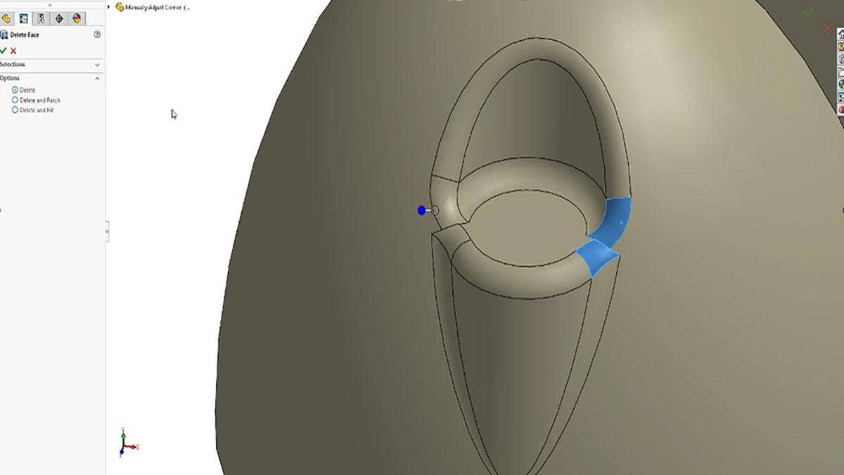
Delete Face
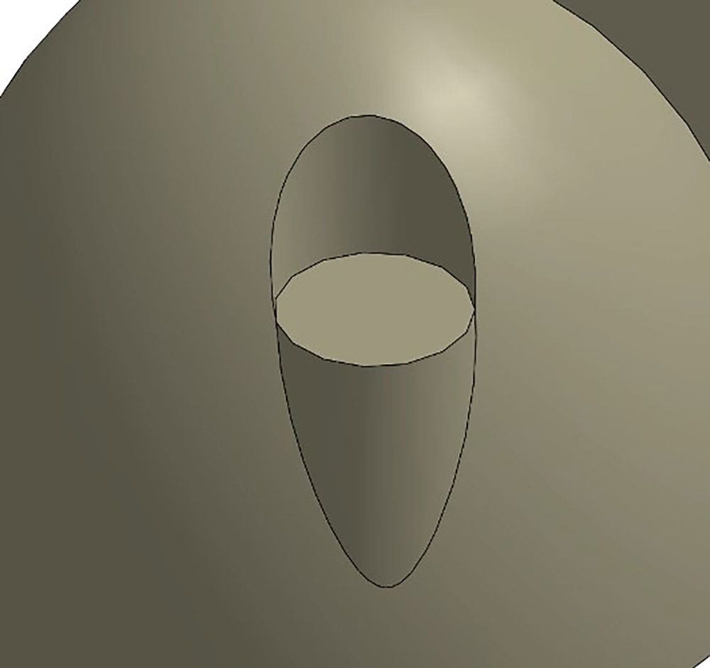
To begin, simply delete the faces of the corner that do not conform to your design intent. In this example, two faces will be deleted while the rest will be left so that they can be manipulated later on.
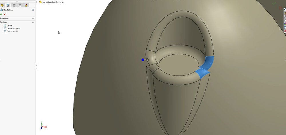
Trim Remaining Faces
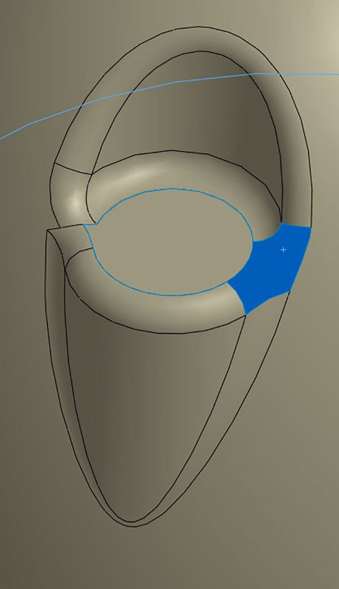
Once the unwanted faces are deleted, the edges of the remaining faces will need to be trimmed in order to create a smooth transition for the filled surface command. These edges can be trimmed either manually or automatically. To trim manually, simply create either a 2D or 3D sketch around the trimming boundary, then activate the Trim Surface command to create the trim. As for the automatic method, a command such as Face Curves or Curve Through Reference Points can be used to automate the creation of the sketch, which will also be used in Trim Surface command.
Filled Surface
Once the edges have been trimmed, the filled surface command can be activated. This will merge all of the trimmed edges in the closed profile together and generate a smooth transition, which the user has full control over the shape.
Watch Tutorial Now
With this workflow, you can now customize the corners of your models to more closely represent your end design goals. Check out our website for more information on SOLIDWORKS, and if you have any questions be sure to contact us at Hawk Ridge Systems today. Thanks for reading!


