SOLIDWORKS has long been known as the industry-leading CAD tool in the world of parametric modeling. But when it comes to creating organic, ergonomic, or form-fitting shapes, modeling parts parametrically may not be so easy.
xShape vs. SOLIDWORKS – Subdivision Modeling vs. Parametric Modeling
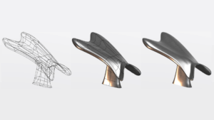
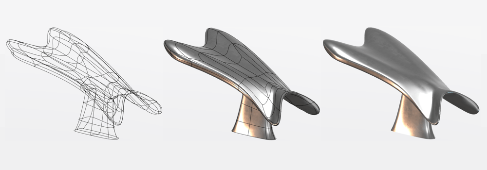
Sweeps, Lofts, and Boundary features are all parametric features in SOLIDWORKS that are great for creating smooth, organic geometries. But when designing for aesthetics or ergonomics, tweaking complex sets of profiles, parameters, and dimensions can require a lot of work. In cases like these, subdivision modeling (often abbreviated as “sub-D” modeling) may have significant benefits over parametric modeling. The basic concept of subdivision modeling is to subdivide a surface into distinct, smaller, more detailed regions, and then manipulate those regions to create the form of our parts.
With sub-D modeling, instead of defining parameters like we do in SOLIDWORKS, we “push” and “pull” the subdivisions of our model geometry. It’s analogous to forming a piece of clay in our hands by squeezing and stretching it to reach our final design. And thanks to the SOLIDWORKS cloud platform, you have access to a powerful sub-D modeling app called xShape as a part of the 3D Sculptor role. You can learn more about the xShape tool in our blog post: Streamline Design with SOLIDWORKS Share & Markup.
Many SOLIDWORKS users are not accustomed to sub-D modeling as it works differently than parametric modeling. We’ll cover useful tips and tricks to get started with sub-D modeling using the xShape tools on the 3DEXPERIENCE platform. Hopefully, these help you get started integrating sub-D modeling into your designs.
If you want to learn more about the types of geometry we can create in xShape, be sure to check out this blog post as well: Subdivision Modeling Made Easy Using 3DSculptor.
Tip #1: Use an Image as a Guide
When designing parametrically, you must often design using strict parameters to ensure your designs meet the desired form, fit, and function. Top-level requirements flow into technical requirements which flow directly into the dimensions and parameters of your models.
Parts designed for aesthetics or ergonomics can have much more “wiggle room”. While there are likely still specific design requirements, you often have much more flexibility to control their form. To be able to meet requirements without limiting yourself to strict parameters, our first tip is: Use an image to guide your designs.
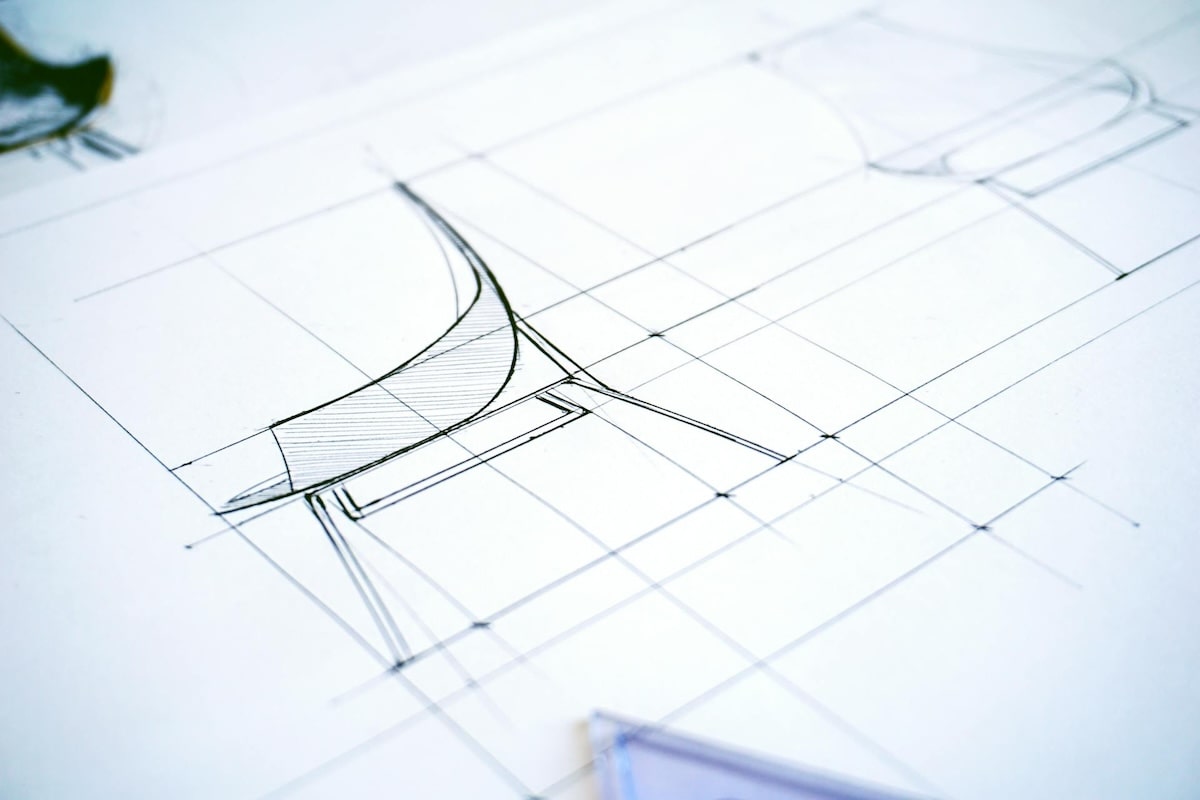
Using a “draft” or guide image to drive your designs before you ever touch your CAD tools can be immensely helpful. Think of it like a mold that you are trying to fit your model into. By starting with an image, or ideally several images, you can use the sub-D modeling tools in xShape to fit your desired shapes.
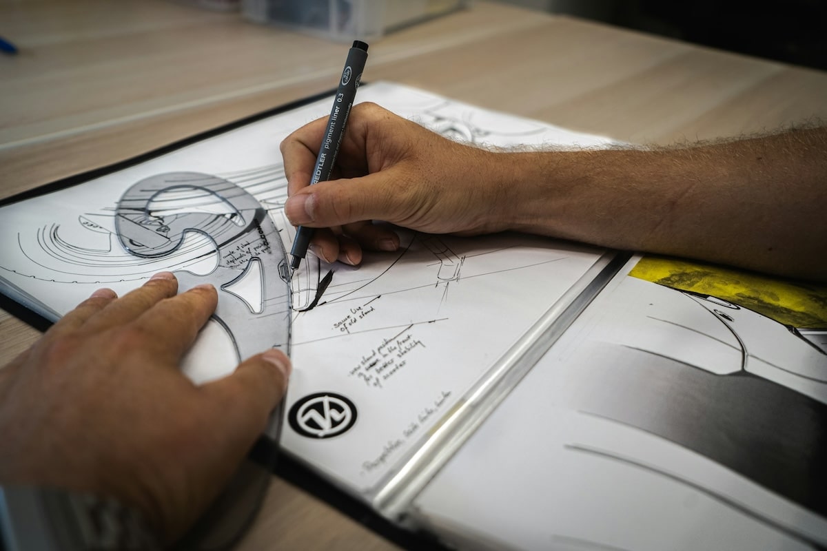
The image can be a photograph or screenshot of a similar part that you want to replicate or update, a drawing that you created in an image editing tool, or even something as simple as a hand-drawn sketch on a piece of paper.
Have an idea for a design and don’t know where to start? Quickly sketch it out on a notepad or piece of graph paper. Getting your concepts onto paper (or digitally if you prefer digital drawing tools) is a great way to start your designs. This allows you to quickly create the basic profiles for your models before you ever open a CAD tool.
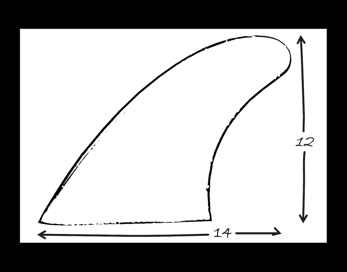
After that, you can simply upload the image(s) and bring them into the xShape app (like using a Sketch Picture in SOLIDWORKS). You can then scale the image to your desired size.
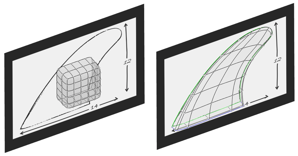
Pro Tip: Make your model semi-transparent so that all the contours of our guide image are visible during the entire modeling process.
Depending on our application, having 3 images is a good baseline — one representing each orthogonal view: Front, Top, and Right. That way you can capture the form of your designs well from three primary orientations. By using these orthogonal views to build out sub-D models, you can gain a high level of control over the form of your parts.
Tip #2: Model from Orthogonal Views (Front, Top, and Right views)
Modeling from orthogonal views is subtly intrinsic to parametric modeling. Usually, you start your parts with a 2D sketch on a reference plane, or in other words, an orthogonal view. When you pull your sketches into 3D with features, you make use of orthogonal views to ensure you have the correct form. Even when creating drawings, standard views are Front, Top, and Right because they often capture a wealth of information about the designs.
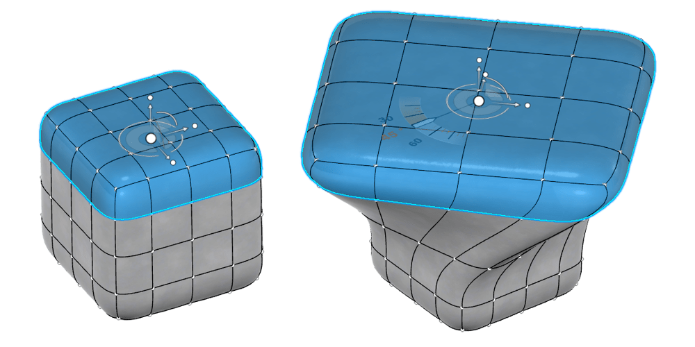
Users new to sub-D modeling often feel like they don’t have the same level of control over their models as they do with parametric modeling. It can be hard to predict how the models will change when you start “pushing” and “pulling” geometry in 3D space. Because of this, sub-D modeling often feels more “fuzzy” than parametric modeling.
You can get over this “fuzziness” by applying the same methodology you apply to parametric modeling: utilizing orthogonal views. In xShape, you can lock the “pushing” and “pulling” to be strictly in the X, Y, or Z directions. By doing so, you can easily shape your models from the Front, Top, and Right views independently without worrying about geometry being pushed or pulled in odd directions. This goes hand in hand with our first tip, using images as a guide — with a guide image for the top, front, and side profiles you can often fully define the overall form of your part.
Note that we can also lock changes relative to the geometry selected or our current screen orientation (see Tip #5 for more on that!). But by starting with the orthogonal views, you can make straightforward, predictable changes to your model’s geometry to get its overall form in place. And then, if needed, you can further detail your models using these other constraints as you see fit.
Tip #3: Start with Broad Changes before Fine-Tuning the Details
When creating models, you want to start with the major features of our geometry first before fine-tuning the details. That typically means adding things like critical interfaces, main body geometry, and large solids before creating more detailed features. For parametric modeling, that usually means creating extrudes, revolves, lofts, etc. to create the general form of parts before using features like ribs, fillets, or chamfers to add the details. For sub-D modeling on the other hand, that means starting the models by pushing/pulling regions or groups of faces/edges/vertices together first.
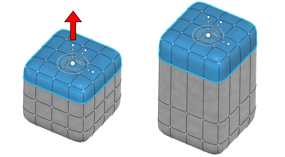
Making big changes first helps create designs with fewer individual manipulations. Think about it this way: would you rather manipulate a section of your model by selecting a group of faces at once or would you rather individually manipulate each edge and vertex one by one for the same result?
Obviously, the answer is the former. It takes much less time to form models by pushing or pulling large sections of geometry at once as opposedf to trying to line up many individual faces, edges, or vertices. Additionally, it’s often easier to get nice, smooth geometry if you save the detailed changes for last. It’s also worth noting that detailed changes can sometimes be wiped out if you make big changes after the fact.
So, as best practice, always start big! Worry about the details after you have the overall form and major details of your geometry complete.
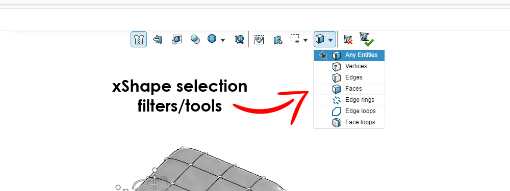
Thankfully, in xShape you have an array of selection tools that enable you to grab large portions of your geometry at once to make these big changes. You can multi-select just like you can in SOLIDWORKS by holding down the CTRL key or by dragging to box-select certain regions. Additionally, there are selection filters that allow you to pick up the exact geometry you want, whether that be faces, edges, vertices, or a combination of all three.
Pro Tip: When doing a multiselect with CTRL + click method, select the first geometry FIRST and THEN hold down the CTRL key for your additional selections. This will automatically hide the modifier robot when making additional selections to prevent accidental manipulations.
But before you begin “pushing” and “pulling”, you need some base geometry to manipulate. When you create a new part in xShape you start with a blank slate, just like when creating a new part in SOLIDWORKS. And in xShape, a big driver in how you can manipulate your sub-D models is with your selection of your starting shape. In sub-D modeling these starting shapes are called “primitives” — which brings us to our next tip!
Tip #4: Using the Right Primitives
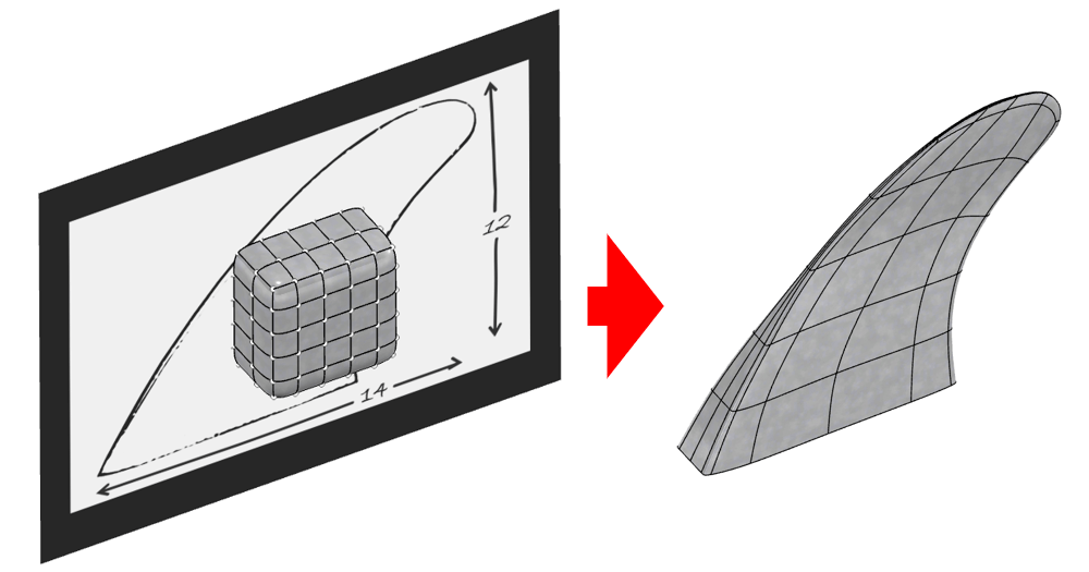
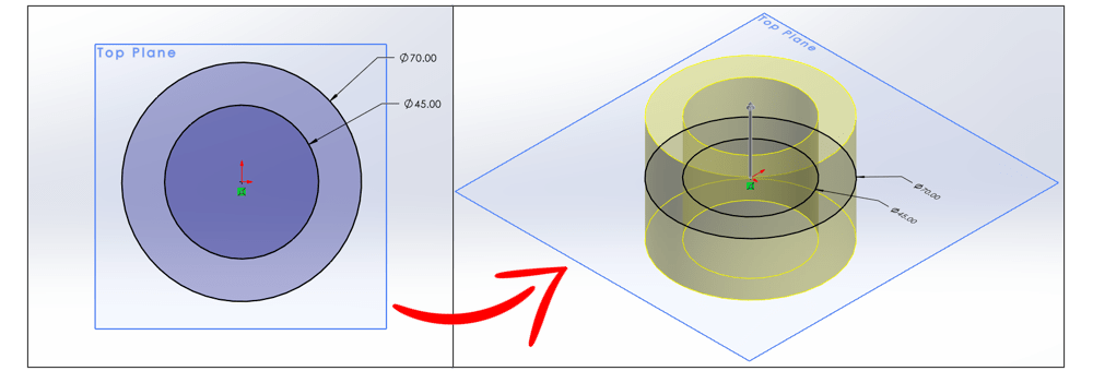
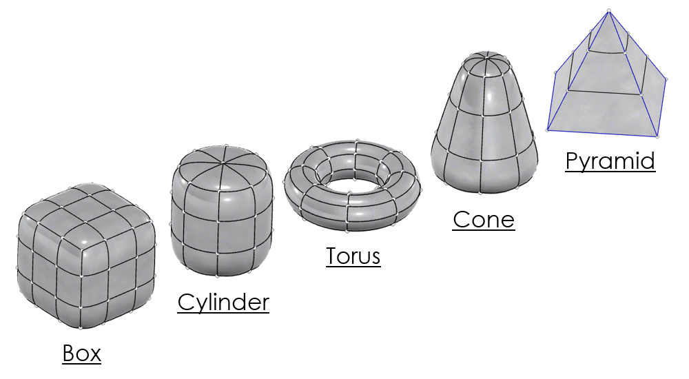
One way that sub-D modeling differs from parametric modeling is the concept of primitives. Primitives represent the basic building blocks in sub-D modeling. xShape has the following primitives available: box, quadball, cylinder, globe, torus, cone, and pyramid. You can consider these primitives to be the base geometry that you “push” and “pull” when forming your model. And it is best practice to choose the primitive that will best match the end geometry you are trying to generate for your parts.
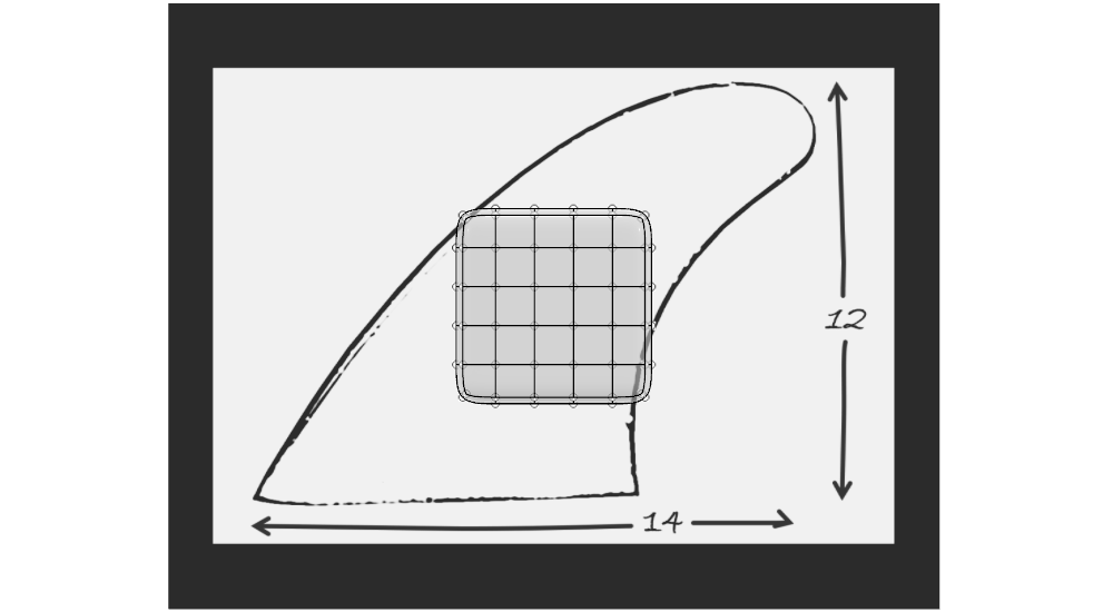
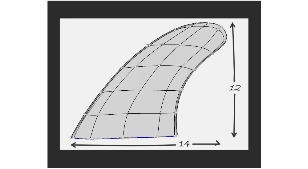
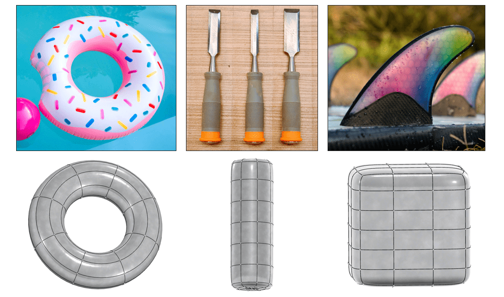
For example, if we are going to model a blow-up pool floaty, the torus might be a good option to start with. If you are designing a grip for an ergonomic handle, the cylinder might be a good primitive to begin your designs. Likewise, if you are modeling something like the fin of a surfboard, you might start with the box primitive.
It’s good practice to put some thought into which primitive will best fit your designs. Doing so can greatly improve the modeling experience by starting off on the right foot.
Pro Tip: When you need a spherical primitive to start your parts, the quadball is often a better starting point than the globe.
The globe primitive is divided very similarly to the latitude and longitude lines on a real globe. As a result, the globe’s surface is subdivided into faces of different sizes and shapes (some with 3 edges, some with 4). While this is perfectly suitable for some designs, the discrepancy in subdivided faces sometimes makes manipulating geometry more challenging. The quadball primitive instead breaks up the spherical surface into roughly equal divisions, all with four edges per face. This often makes the primitive easier to manipulate, especially for users new to sub-D modeling.

In any case, when starting off designs, choosing the right primitive will certainly put you on the right path to reaching your final designs.
Tip #5: Check the Modifier Robot Constraints Often
The last tip we have for you has to do with the “modifier robot”. The modifier robot is what we call the active handle we use to “push” and “pull” our geometry in xShape. When selecting a region, face, edge, or vertex, the modifier robot appears as a triad on that selected geometry. Using the modifier robot, you can manipulate your geometry in any direction in 3D space.
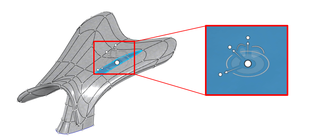
As we mentioned back in Tip #2 (model using orthogonal views) often it can be useful to restrict the directions in which we can pull the modifier robot. We can constrain the modifier robot with 3 different options:
- Relative to the selected geometry
- Relative to global the X, Y, Z
- Relative to the orientation of our screen
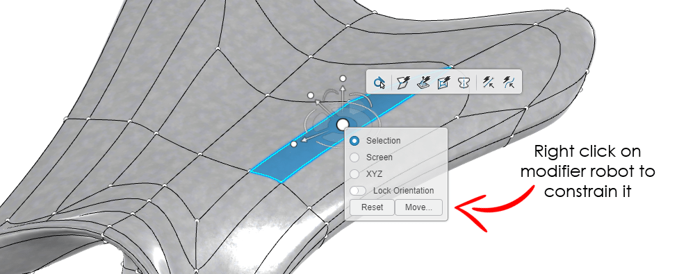
You can move the modifier and lock your constraints, even if you select new geometry, by right-clicking on the robot. This can make modeling using guide images (Tip #1) and orthogonal views (Tip #2) a cinch.
However, it is possible to accidentally “unlock” the constraints of the modifier robot. This can be a potential pitfall for users new to xShape. An errant click or misselection can unlock the modifier robot, often with little or no feedback to the user. If this happens, you may be modeling with your guide image in an orthogonal view, only to rotate the view and find that the geometry has been pulled in all kinds of unintended directions.
Therefore, the real tip here, particularly when first starting out with xShape, is to check the orientation of the modifier robot often. That way you can be sure that the model behaves in predictable ways when “pushing” and “pulling” the geometry from various views.
Tip 6: Use Parametric and Sub-D Modeling Together
While many SOLIDWORKS users are well-versed in parametric modeling, subdivision modeling can seem like an entirely different beast. But that doesn’t mean that you can’t utilize it alongside your parametric modeling in your engineering designs. Our final tip to close out this blog post is: Don’t feel constrained to just one modeling method.
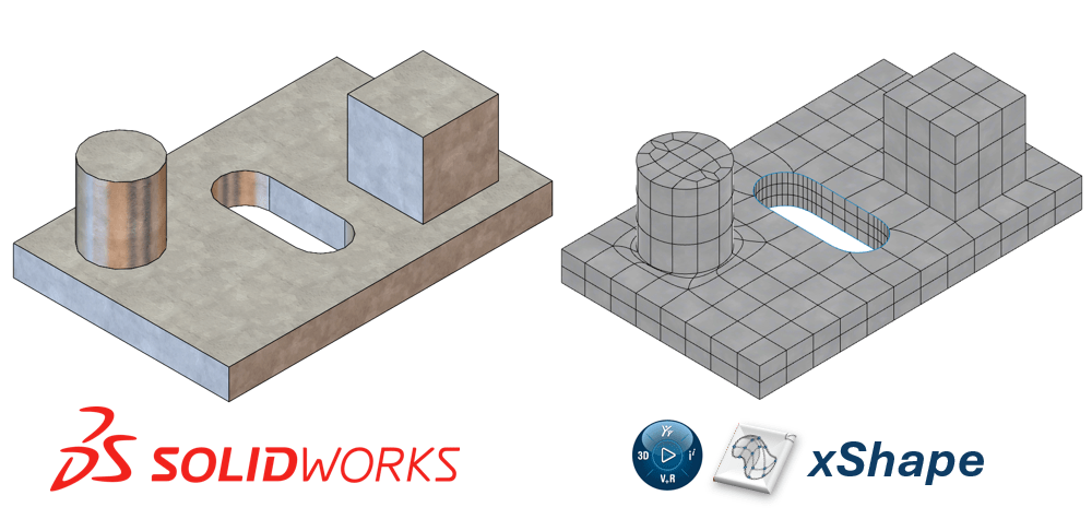
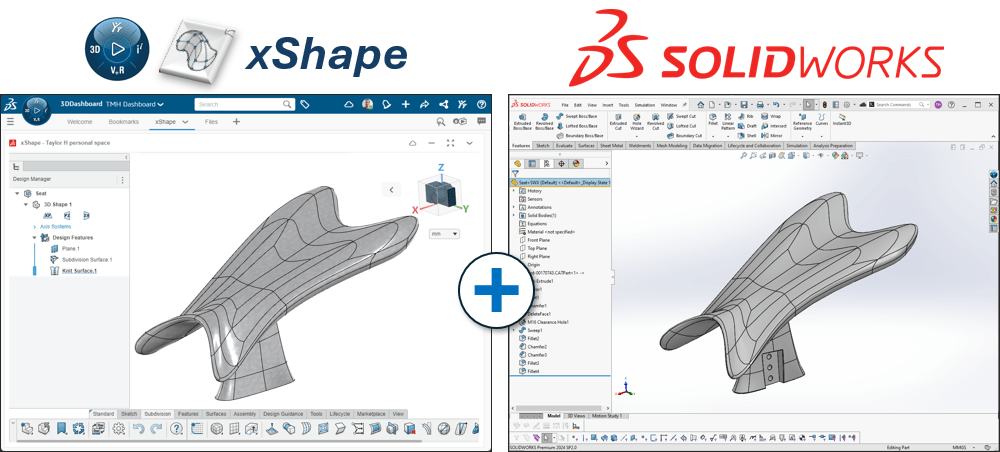
The precision of the parametric tools in SOLIDWORKS desktop and the flexibility of the subdivision tools of the xShape tools on the SOLIDWORKS cloud complement each other greatly. You can use these tools in conjunction to get the full power of both. In fact, xShape can be used in conjunction with almost any CAD software—CATIA, Inventor, Fusion, NX, etc. (many of which you learn to use on SolidProfessor).
Pro Tip: All of the SOLIDWORKS cloud tools, such as xShape or the parametric modeling tool xDesign, are designed to be used with nearly every professional CAD package. Feel free to connect with us to see how these tools can be integrated with your specific workflow.
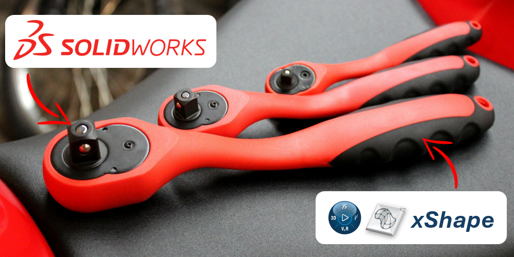
For example, imagine that you are designing an ergonomic handle for a hand tool, such as the example ratcheting wrench below. You can model the grip itself in xShape to get that smooth, organic geometry that is form-fitting to human hands. You can then pull that same part into SOLIDWORKS desktop (or vice versa) to model the “business” end of the tool. Thanks to the SOLIDWORKS suite of CAD solutions, you can utilize both their strengths to fully realize your designs. Check out our blog post on SOLIDWORKS CAD options here: 3 SOLIDWORKS Options Explained: Choosing Your 3D CAD Tools.
Hopefully, the tips and tricks in this post help you on your journey with the subdivision modeling tools in xShape and the 3D Sculptor role. If you have any other questions about these tools or how to use them, feel free to reach out! We at Hawk Ridge Systems are always here to help be a partner in your success with the SOLIDWORKS family of tools.