In our previous post, “Spur Gears in SOLIDWORKS Part 1: How to Quickly Include Spur Gears in Your Assemblies ”, we discussed making use of the spur gear component in the SOLIDWORKS Toolbox. With the Toolbox, you have a seamless way to integrate standardized parts, like spur gears, into your designs.
When you need to include gears in our assemblies, the out-of-the-box Toolbox spur gear component can often be the perfect fit. It can help you to design more efficiently and can significantly reduce modeling time — but are there limitations to its use?
The SOLIDWORKS Toolbox Spur Gear: When is it Appropriate to Use?
No tool is truly “One Size Fits All” and the Toolbox spur gear component is no exception. It’s easy to configure and use, but you should consider its range of applicability. Like any tool available to you in the engineering world, you should ask yourself: when is it appropriate to use?
To answer this question, you should first get familiar with the SOLIDWORKS Toolbox spur gear component to gain some insight into how it works.
As we know, a spur gear is a standardized component. Much like a fastener, bearing, or O-ring, its geometry is defined by various engineering standards. Using these standards, and standardized parts they define reduces modeling time. In the case of the spur gear, you can make use of standards such as ISO, ANSI, or Mil. Spec. to define the gear geometry.
Luckily, SOLIDWORKS gives you an easy way to utilize these engineering standards via the Toolbox. The Toolbox components essentially have these standards “baked-in” to their models. For our spur gear, this allows us to define certain gear parameters, such as diametral pitch and number of teeth, and the Toolbox automatically builds the model for us. These “baked-in” standards also ensure that the Toolbox models are representative of their real-world Commercial Off-the-Shelf (COTS) counterparts. In many cases, no sketching or feature creation is required on your part.
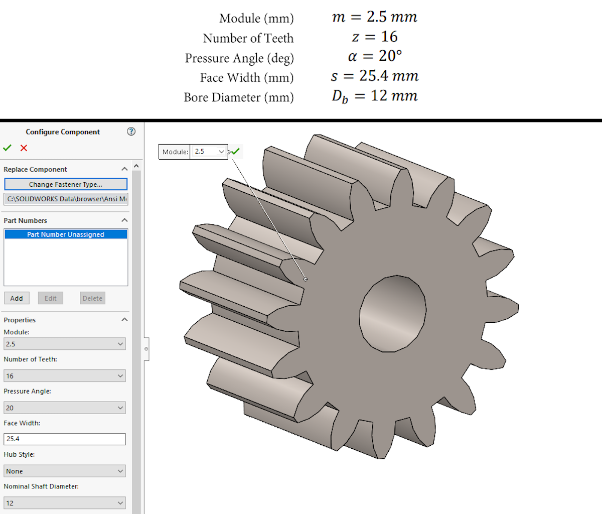
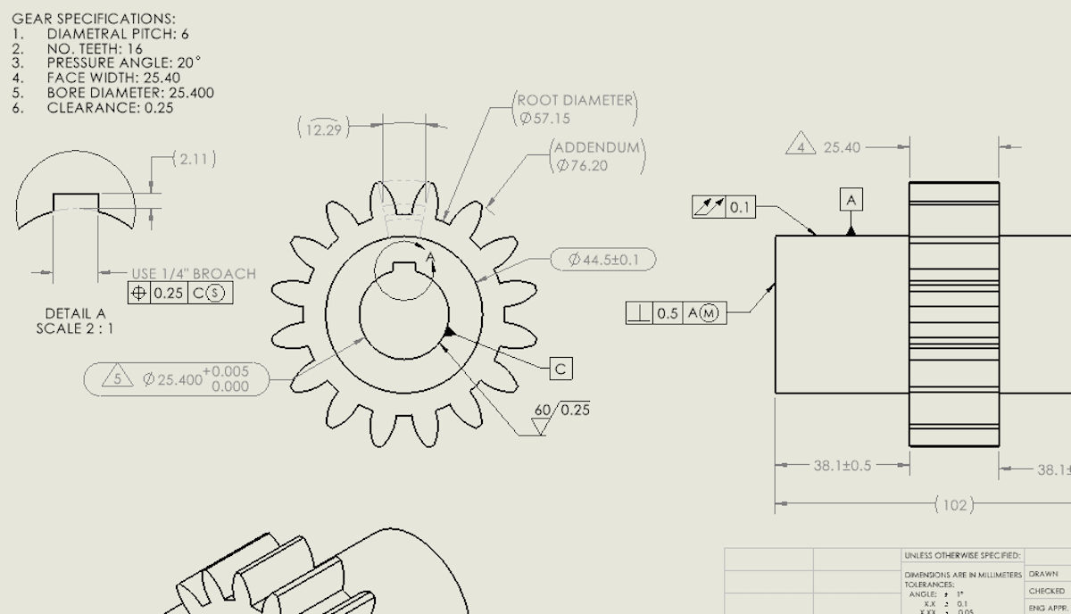
The image below gives an example of a sample Toolbox spur gear and the parameters we would input in SOLIDWORKS to define it. While there are many parameters to consider when designing a spur gear, these five parameters define its major geometry, both in SOLIDWORKS and in the real world. The Toolbox is able to translate the inputs into a CAD model specifically thanks to those “baked-in” engineering standards.
Toolbox Spur Gear Geometry vs. Real Spur Gear Geometry
The caveat to using the SOLIDWORKS Toolbox spur gear is that the model geometry is an approximation. It’s representative of a real gear, but it is not exact. There are differences we must consider when using it. The most notable difference has to do with the shape, or profile, of the individual gear teeth. In short, the Toolbox spur gear uses a semi-arbitrary circular arc to represent the tooth profile while a real spur gear most often uses an involute curve. So, what does that mean?
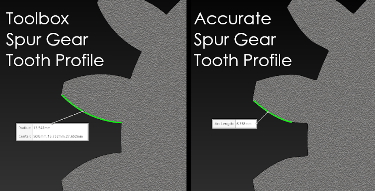
Given the same gear parameters, it might be hard to see the difference between a model with accurate spur gear geometry and a model created using the Toolbox. The image below shows two spur gears created in SOLIDWORKS with the same input parameters. They both have 16 teeth, a pressure angle of 20°, a diametral pitch of 6, and the same thickness and bore diameter. The gear on the left is the SOLIDWORKS Toolbox spur gear. The gear on the right is modeled with the accurate spur gear tooth geometry.
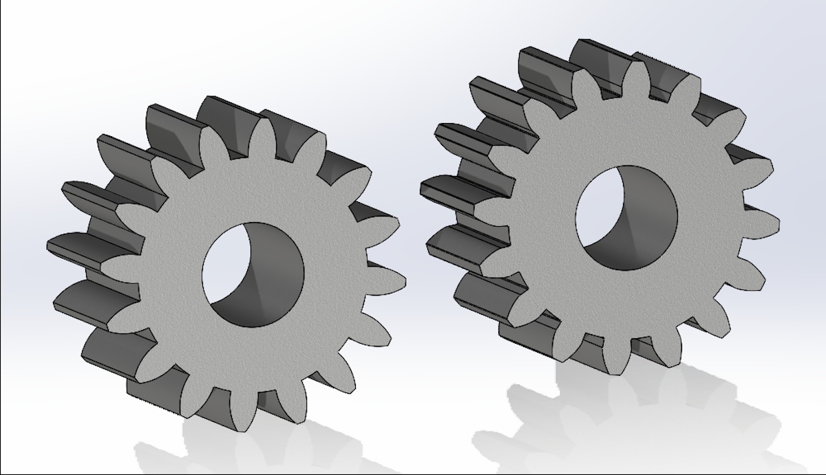
Despite using the same input parameters, these models have slightly different geometry. The circular arc used for the Toolbox gear teeth means that each tooth face has a constant radius of curvature. In other words, it has a measurable radius and a defined center point. We can see this ourselves by measuring the edge of the Toolbox spur gear tooth with the Measure tool as shown in the image below.
On the other hand, if we measure a similar edge on the accurate spur gear model, we get different results. Because the edge on the accurate gear model is defined by an involute, which has a variable radius of curvature, there is no measurable radius or center point. For the accurate spur gear model, only the arc length of the edge is shown.
If we interrogate the models further, we see that there are some other minor differences as well. For instance, there is no well-defined contact surface on the Toolbox spur gear teeth. Instead, the circular arc defining the tooth profile simply extends fully from the tooth tip to the tooth root. The face, flank, and undercut are essentially merged into a single surface. This contrasts with an accurate spur gear model whose teeth have well-defined contact surfaces and distinct geometry along its profile. There are also small dimensional differences between the two gear models such as top land width, root depth, tooth clearance, chordal thickness, etc.
While these differences are typically minor, it is important to note that they exist.
OK, We Know They Are Different, but Does it Matter?
At this point, you may be asking: Do these differences matter? Thankfully, the answer is often no.
Despite the variations between the two, the SOLIDWORKS Toolbox spur gear is still suitable for most applications. It works well for quickly incorporating gears in your assemblies, populating BOMS, or doing basic motion analysis in SOLIDWORKS. Because spur gears are standard components, the approximate geometry is acceptable for your designs in most cases.
Much of the time, the Toolbox spur gear models are even suitable for our manufacturing prints. Because the gear parameters drive the major aspects of spur gear geometry, the CAD model we use for our print isn’t critical for manufacture. In this case, drawing views are often used for reference only or to call out dimensions not specified by the gear parameters, such as inspection dims and tolerances. Any decent gear manufacturer will machine the correct spur gear geometry as part of the manufacturing process itself (typically hobbing, shaping, or grinding) using the gear parameters.
Why Doesn’t the SOLIDWORKS Toolbox Spur Gear Use Accurate Geometry?
So, why does the Toolbox spur gear use a circular arc for the tooth profile instead of an accurate involute curve? One likely reason is that a circular arc is a very simple entity in SOLIDWORKS. As a result, a circular arc takes little computational power to resolve.
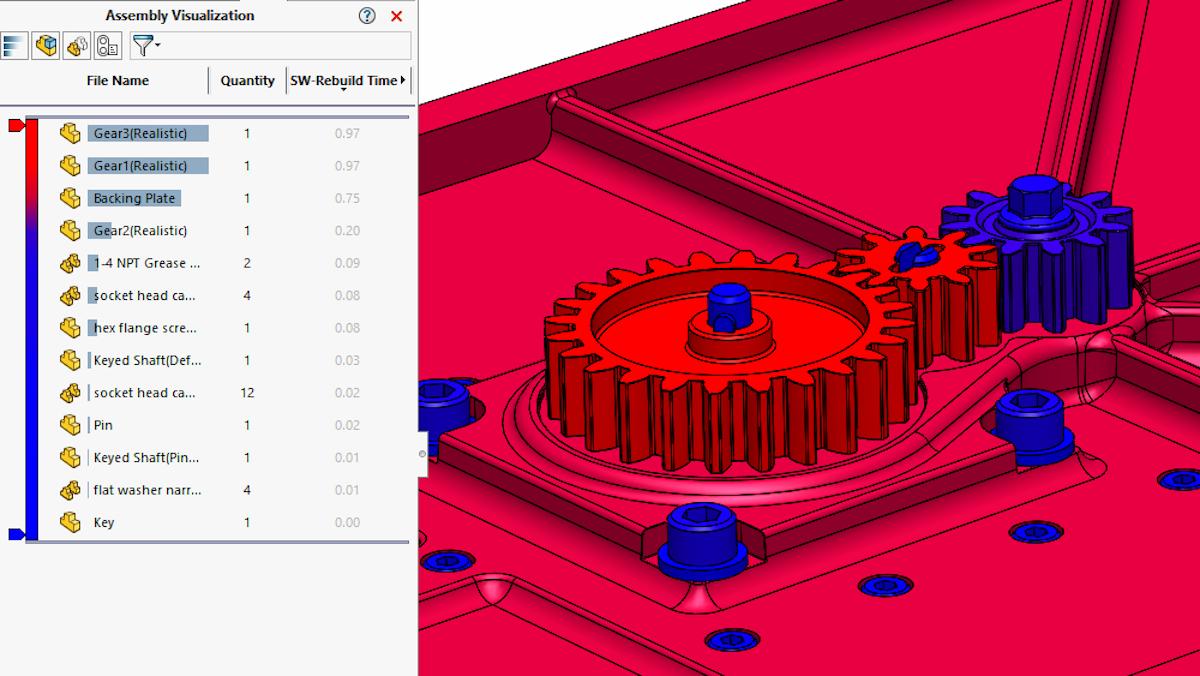
You only need a few pieces of data to define it: a center point, a radius, and end points. Conversely, an involute has variable curvature and is not so simple to generate. While involute curvature gives you optimal meshing characteristics between gears, it comes at the expense of added complexity. This added complexity means that accurate involute spur gears take longer to rebuild and can bog down system performance, especially in large assemblies.
Therefore, you can think of the circular arc tooth profile as somewhat of a compromise. It’s accurate enough that it works for most applications without being too computationally intensive. Using involute curvature for your gear teeth is more accurate, but often you don’t need that level of accuracy. In general, the computational cost generally outweighs the benefits of more accurate gear geometry.
When Might the SOLIDWORKS Toolbox Spur Gear Not Work?
At this point, you might be asking: Are there use cases where “real” gear geometry is necessary? Cases where the Toolbox spur gear just won’t cut it?
Every tool in our engineering toolbelt has a certain range of applicability. We must evaluate the problem you are trying to solve so that you can choose the right tool for the job. You wouldn’t use a screwdriver to hammer a nail into a piece of wood, right? The same goes for the components in the SOLIDWORKS Toolbox. As it turns out, there are certain applications where you might need a more accurate spur gear model.
Case 1: Making Gears from Exotic or Non-Standard Materials
One case might be if you need to make your spur gears from an exotic or “difficult” material, such as tungsten carbide, which can require a non-traditional manufacturing process.
Milling, hobbing, or even grinding tungsten carbide can be challenging because it is extremely hard and very brittle compared to most metals. It often requires special tooling that many gear manufacturers are not set up for or might not have on hand. Many shops flat out refuse to work with it. In this case, the best manufacturing method might be something non-traditional, such as wire Electrical Discharge Machining (EDM).
Wire EDM is a great fit for machining the 2-D profile of a spur gear and can easily machine a conductive material like tungsten carbide. If you have any familiarity with wire EDM, it’s easy to see why the approximate geometry of the Toolbox spur gear will not work. The wire EDM manufacturing process requires accurate geometry so that the correct toolpath is generated to cut the physical gear. The final cut gear in this case is ideally one-to-one to our CAD model geometry.
This also might be the case if we are using a material like glass fiber or carbon fiber-reinforced Nylon. You might use these materials for special environments, prototyping, or purely for cost reasons.
Unfortunately, machining fiber-reinforced thermoplastics can be abrasive to tooling leading to high tool wear. They also don’t typically pull heat away well when machined which can cause dimensional instabilities. As a result, they can be difficult to work with, especially when trying to hold tight tolerances, potentially leading to high wastage.
On the other hand, these materials lend themselves very well to additive manufacturing. Using a 3D printer such as the Markforged FX20 to manufacture a spur gear in carbon-reinforced Onyx or glass-reinforced Nylon is trivial. While traditional machining methods can struggle with these materials, 3D printers excel.
Just as with our example using tungsten carbide, this is a case where approximate gear geometry is not sufficient. The one-to-one relationship between the CAD model and the 3D printed part requires that you have an accurate spur gear model.
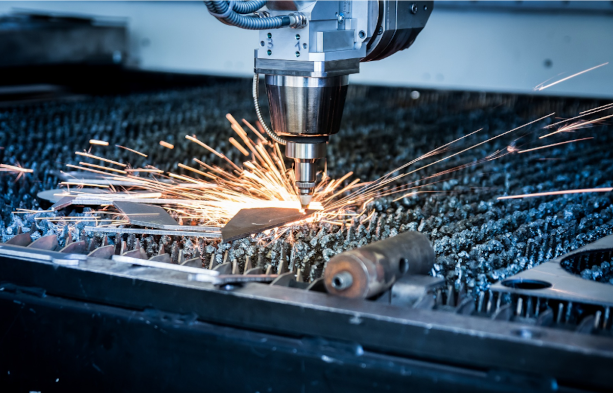
The same logic goes for machining processes that operate similarly, such as waterjet cutting, laser cutting, or plasma cutting. Each of these methods of manufacture requires a true-to-form CAD model to produce the correct geometry.
Case 2: Using our Spur Gear Models for Detailed Analysis and Simulation in SOLIDWORKS
Accurate gear geometry can also be important during the design phase. If you plan to do any in-depth motion analysis, you need an accurate CAD model. Without it, you won’t be able to correctly represent the interaction between individual gears or other parts of your assembly. Traits such as backlash, gear meshing characteristics, or the effects of things like pitch deviation or undercut cannot be correctly evaluated without an accurate gear model.
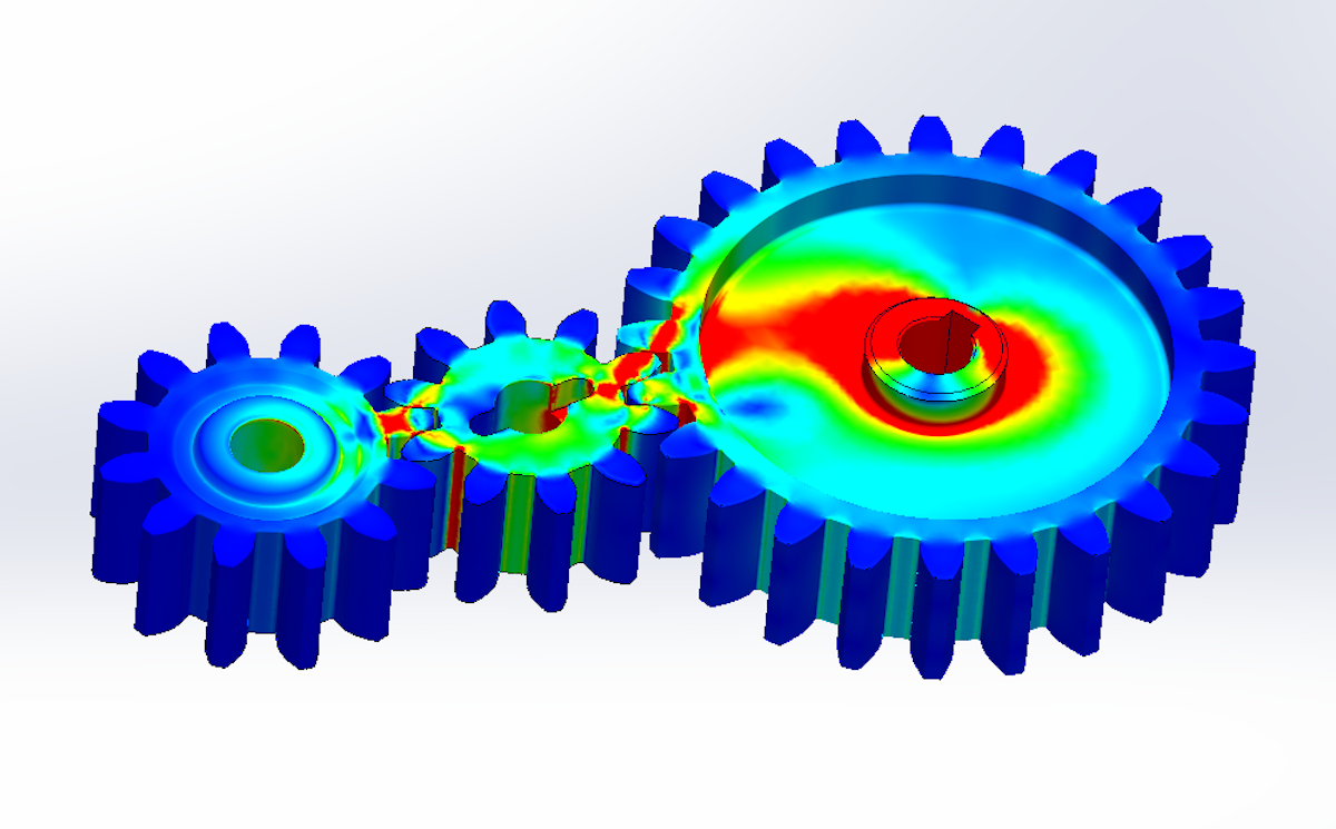
Similarly, if you want to run simulations on our assemblies to evaluate things such as stress, vibration, or fatigue, you need true gear geometry to ensure that your results are accurate. This is particularly important when doing design optimization with SOLIDWORKS Simulation. Without accurate geometry, any “optimizations” or design decisions you make based off simulation results can lead you down the wrong path.
The same reasoning applies if you are doing Computational Fluid Dynamics (CFD) analysis with your gear assemblies using SOLIDWORKS Flow Simulation. This might be the case if you are designing a positive displacement pump or a submerged geartrain and are trying to meet specific design points. Using Flow Simulation, you can perform CFD on assemblies with rotating components, like your spur gears, but the results will not be realistic if your models are not accurate.
The SOLIDWORKS Toolbox spur gear could be used when doing this analysis, but its application is typically limited to the conceptual or early preliminary design phase. If you are doing some initial sizing early in the development process, the Toolbox spur gear might work just fine. But this is not the case if you need to do detailed analysis or simulation during the detailed or critical design phase. Designing custom gears or evaluating the performance of your gear assemblies requires additional fidelity not captured by the Toolbox component.
Modeling Accurate Involute Spur Gears in SOLIDWORKS
Now that you have some insight into the Toolbox spur gear and the differences between it and a real spur gear, what’s next?
The Toolbox spur gear is likely the right answer for most of your applications and you should take advantage of it as much as possible. But as you saw in this blog post, it is critical that you analyze your use case to determine if the Toolbox spur gear is appropriate. While it is very close to true spur gear geometry, it is still an approximation when it comes down to the details.
After reading through this blog post, you might wonder what to do if you run into one of those cases where you need an accurate spur gear model. Well, the answer is straightforward: you need to model the spur gear yourself. Sounds simple enough, but how do you go about that? You know that spur gears use an involute curve to define the tooth profile, but what does that mean? Where do you start?
To answer these questions, be sure to check out our final blog post in this series: “Spur Gears in SOLIDWORKS Part 3: How to Model Accurate Involute Spur Gears in SOLIDWORKS ”.
As always, if you have any questions, be sure to reach out! Contact us at Hawk Ridge Systems to discuss how the suite of SOLIDWORKS software can improve your workflows and designs.