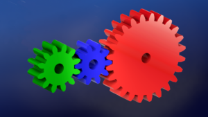
If you deal with mechanical systems, chances are that you have come across a gear or two in your line of work. Gears come in many different forms including helical, herringbone, worm, bevel, and many others, each with a different application. In this blog post we will look at one of the most commonly used types of gear, the spur gear, and how we can include them in our SOLIDWORKS assemblies.
Spur Gears: Why Use Them and What Are They Used For?
Spur gears have a constant profile, straight-cut teeth, and most often have gear tooth geometry defined by an involute curve. Spur gears are what typically pops into most people’s minds when they hear the word “gear”.
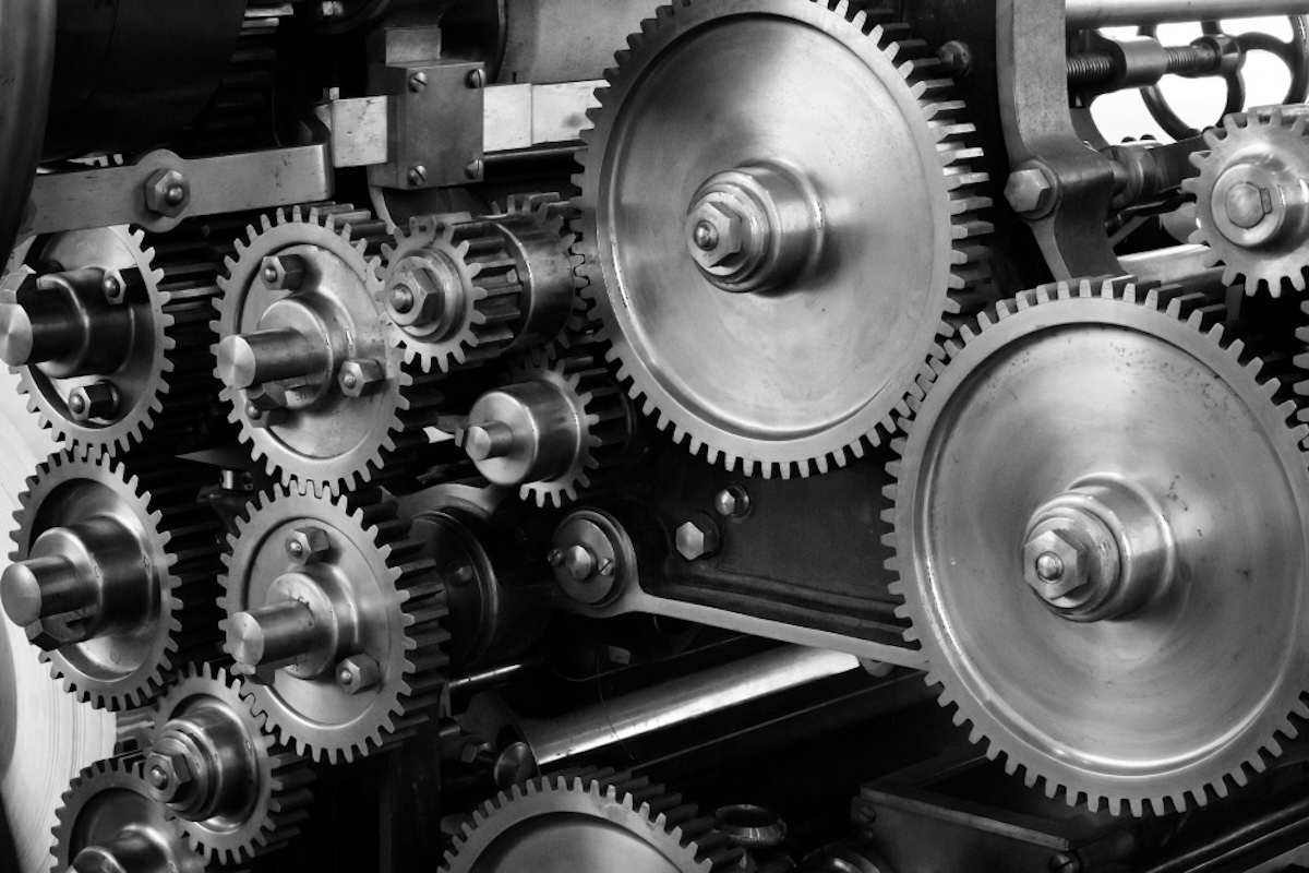
If we are designing a system that transmits power or motion, spur gears can often be the perfect fit in our assemblies to meet our design requirements. Spur gears are used across nearly every industry from aerospace to industrial machinery to consumer-level goods.
And there is good reason for their widespread use:
- They are easy to manufacture
- Generally low-cost
- Highly efficient
- Extremely reliable when designed appropriately
It’s easy to see why spur gears are so common in modern engineering—and we’ll soon see how easy they are to include in our SOLIDWORKS assemblies.
How Can We Include Spur Gears in Our SOLIDWORKS Assemblies?
Once we have determined that spur gears are the correct fit for our designs, the next logical question is: how can we incorporate them into our SOLIDWORKS assemblies?
The first option that might come to mind is to simply model the spur gears ourselves. Modeling a spur gear manually is certainly doable for anyone with decent SOLIDWORKS skills—for example, anyone who has taken our SOLIDWORKS Essentials class should be able to build a gear model relatively easily.
Spur gears are standardized parts defined by engineering standards, just like nuts and bolts. So, why spend time modeling a part when its geometry has already been standardized?
SOLIDWORKS has a quick and easy solution when it comes to using standardized components, such as spur gears: the SOLIDWORKS Toolbox.
Introducing the SOLIDWORKS Toolbox
The Toolbox included with the Professional and Premium versions of SOLIDWORKS is an incredibly powerful tool that gives you access to a wide range of standardized parts. This includes items such as:
- Fasteners
- O-rings
- Keys
- Bearings
- Components for transmitting power (including spur gears).
The Toolbox components are defined and categorized by various international engineering standards, such as ISO, ANSI, Mil. Spec (MS), DIN, and JIS—so no matter the application, you can be sure that the SOLIDWORKS Toolbox has a component that meets your design requirements.
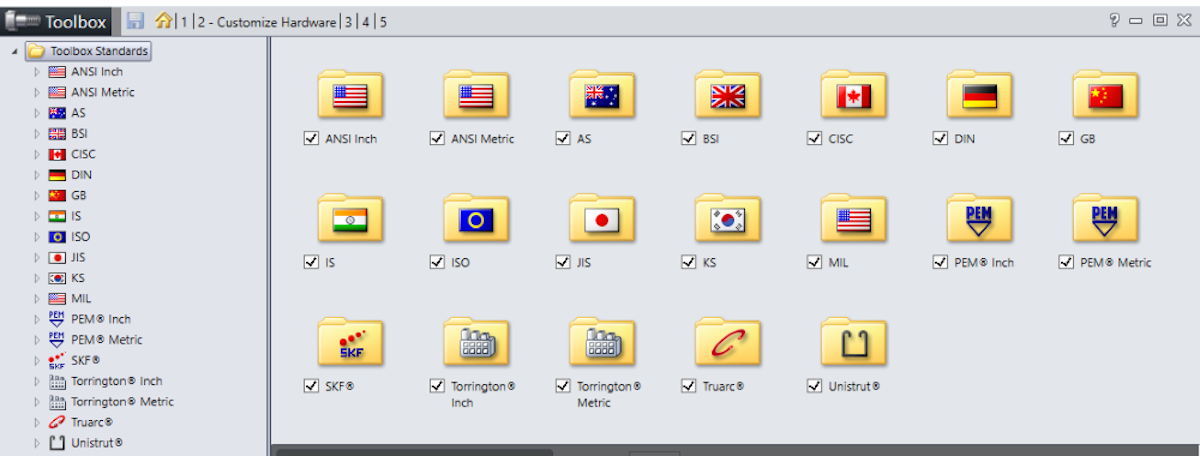
The models included in the SOLIDWORKS Toolbox are fully configurable, allowing you to customize components, like the spur gear, to precisely match the needs of your design.
For most applications, the SOLIDWORKS Toolbox helps eliminate modeling “grunt” work by automating the modeling process. You can define your input parameters for a Toolbox component and SOLIDWORKS adjusts the model automatically. As a result, using the SOLIDWORKS Toolbox can improve your workflows and reduce time spent modeling. If you need to include a standardized component like a spur gear in your assembly, the SOLIDWORKS Toolbox is the place to look.
You can check out some of the additional features of the Toolbox and a quick tutorial on how to use it here: SOLIDWORKS: Toolbox Your One Stop Shop.
Adding Spur Gears to Our Assemblies Using the SOLIDWORKS Toolbox
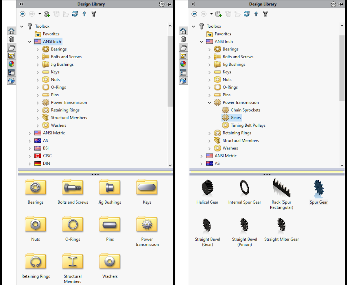
To access the spur gear component of the SOLIDWORKS Toolbox, open the Design Library from the Task Pane and then select the “Toolbox” folder. From there, you can navigate to the appropriate standard, such as ANSI or ISO, select “Power Transmission”, and then “Gears”.
Within the “Gears” folder, you have access to multiple gear types offered by the Toolbox. To include a spur gear in your assembly, you can simply drag and drop the spur gear icon from Task Pane into the Graphics Area and, BAM! — you have a spur gear!
After dropping the spur gear into your assembly, the Toolbox component Property Manager opens to allow you to customize the gear to fit your needs. Here, you can input the necessary defining parameters for your spur gear that generate the model geometry, including:
- Diametral pitch (or module for metric gears)
- Number of teeth
- Pressure angle
- Face width (gear thickness)
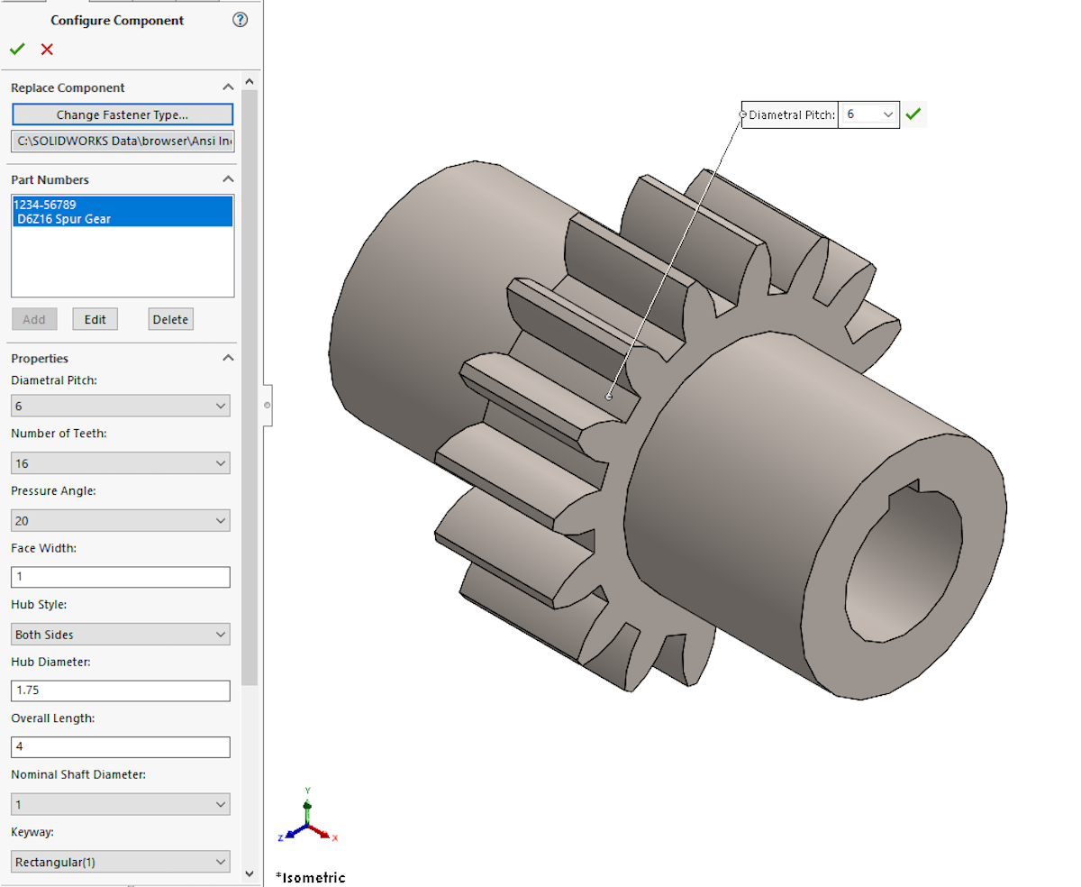
The Toolbox additionally allows you to define secondary gear geometry such as a bore diameter, keyways, or hubs on one or both sides of the gear. From the Property Manager, you can also add custom file properties such as part number, part description, and configuration name to your spur gear as you create it. This means that when you include your spur gear in something like a Bill of Materials (BOM) on an assembly drawing, those fields are automatically populated.
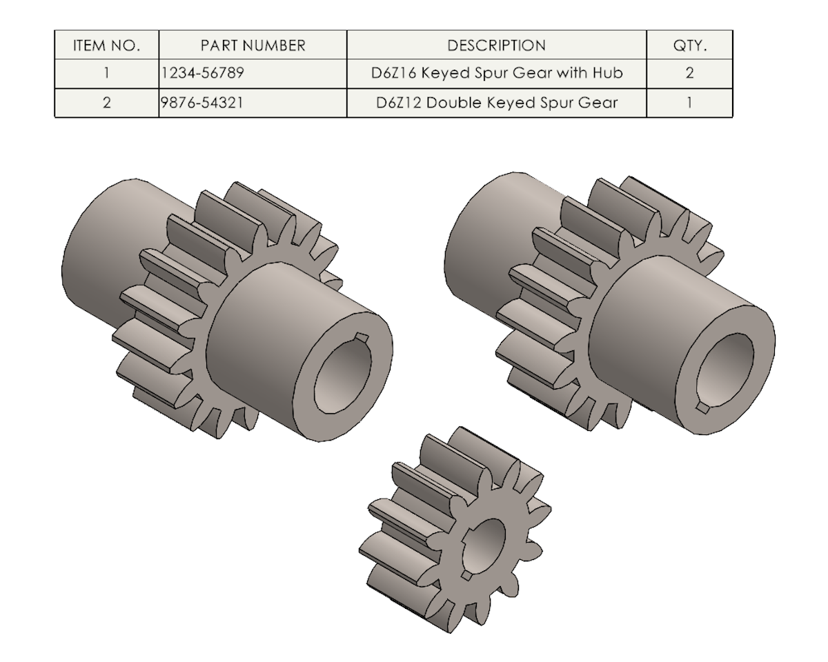
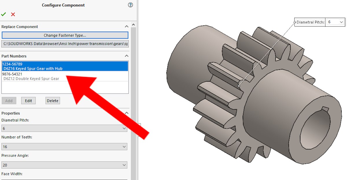
Once you’ve configured your spur gear and assigned it a part number via the Toolbox component Property Manager, that configured gear is automatically stored for future use. This means that you only need to specify the gear parameters, part number, and description a single time, even if you are using the gear in multiple assemblies.
Once defined, that specific spur gear can be re-used simply by selecting it from the list of existing part numbers in the Toolbox component property manager. Using this method, you can build up a collection of gears (or really, any Toolbox component) each with unique input parameters and part numbers that you can use (or modify) at any time.
The SOLIDWORKS Toolbox is a one-stop shop for adding standardized components to your assemblies. It allows you to configure your spur gear and implement it in your designs quickly and easily across multiple assemblies with only a few clicks.
Utilizing the SOLIDWORKS Toolbox Components to Design More Efficiently
It’s easy to see why the SOLIDWORKS Toolbox is so powerful. The Toolbox helps save time and increases design efficiency by automating the modeling process and making use of built-in engineering standards.
If you were to manually model a spur gear, you’d need to reference the applicable gear standards and generate your own sketches and features—eating up valuable design time. But with the Toolbox, you simply specify a few input parameters and SOLIDWORKS generates your model to spec automatically.
If you are a user of SOLIDWORKS Product Data Management (PDM), the Toolbox can even be integrated with the PDM service for further customization and management of Toolbox components.
Using the SOLIDWORKS Toolbox Spur Gear Component in Practice
The SOLIDWORKS Toolbox is an amazing tool to have in your engineering toolbelt and I would recommend using it whenever possible. It’s important, as an engineer, to evaluate the applicability of the tools and methods on a regular basis.
But is the SOLIDWORKS Toolbox spur gear component a good fit for ALL applications?
All tools have a certain range of applicability, no matter if it’s software, a piece of machinery, or a simple hand tool — the SOLIDWORKS Toolbox is no exception. While the standardized components in the SOLIDWORKS Toolbox work for most designs, there are a handful of niche applications where the out-of-the-box spur gear component may not work.
To take a closer look at some of those niche applications and how they might affect using spur gears in SOLIDWORKS for your designs, check out our follow-up blog post: Spur Gears in SOLIDWORKS Part 2: How to Determine if the Toolbox Spur Gear Component is a Good Fit.
If you have any questions, be sure to reach out! Contact us at Hawk Ridge Systems to discuss how the suite of SOLIDWORKS software can improve your workflows and designs.
