Welcome to our third and final blog post in our series on using spur gears in SOLIDWORKS!
Spur gears are one of the most common types of gears used in a wide range of applications from consumer-level products to advanced industrial and aerospace applications. They have straight-cut teeth with a constant profile making them relatively easy to manufacture and incorporate into designs. As a result, they can often be an inexpensive and efficient solution when you need to transmit power or motion in our SOLIDWORKS assemblies.
The SOLIDWORKS Toolbox Spur Gear and When to Use It
In our first blog post in this series, “Spur Gears in SOLIDWORKS Part 1: How to Quickly Include Spur Gears in Your Assemblies“, we discussed the basics of the SOLIDWORKS Toolbox spur gear and how to use Toolbox components. We saw how the Toolbox allows us to quickly configure and implement spur gears in our assemblies, allowing us to design and model more efficiently.
In our follow-up blog post, “Spur Gears in SOLIDWORKS Part 2: How to Determine if the Toolbox Spur Gear Component is a Good Fit”, we looked at the specific geometry of the Toolbox spur gear and discussed its applicability. In that post, we discovered that the Toolbox spur gear CAD model is actually an approximation to true spur gear geometry. While a physical spur gear most often uses an involute curve to define its tooth profile, the Toolbox spur gear uses a simple constant radius curve.
Nine times out of ten, the approximate geometry of Toolbox spur gear will work just fine, but there are certain applications where accurate involute geometry is required. This might be the case if you need to perform simulation or flow analysis with your gears, as accurate models are required for accurate results. You also need a true-to-form gear model if you are manufacturing gears with non-traditional methods, such as with additive manufacturing or wire EDM, where the manufactured part is essentially a one-to-one of the CAD model.
Spur Gears and Involute Geometry
So, why do real spur gears use involute geometry in the first place? Well, when an involute is rotated about its center with a constant angular velocity, a surface that is tangent to it will translate with a constant linear velocity. This results in smooth, uniform motion when a rotating part, such as a spur gear, is used in an assembly. You can see this motion in SOLIDWORKS in the next image with the involute shown in red and the tangent surface shown in blue. The grey line/arrow represents the line of action, or in other words, the path traced out by the contact point between the involute and the tangent surface. Note that the line of action as well as the speed and direction of the blue tangent surface are constant as it translates.
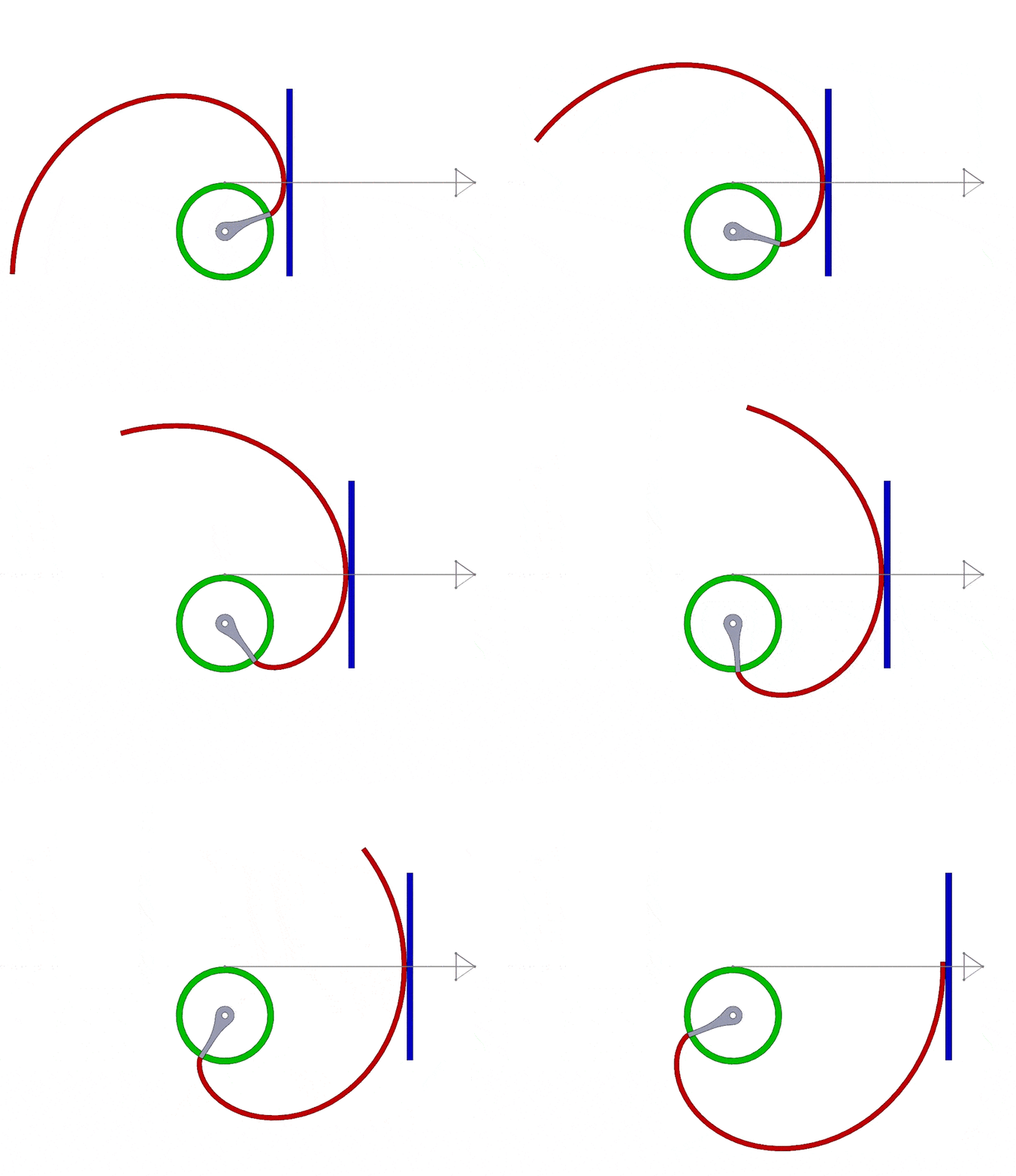
This behavior is representative of what happens when two meshing, or interlocking, involute spur gears rotate. With involute tooth geometry, the motion between the two meshing spur gears is uniform and smooth. It also gives a high tolerance for parallel misalignment, or in other words, it gives you a relatively large amount of wiggle room when spacing two gears in an assembly. Using involute geometry also means that the shape of the teeth of an individual spur gear only depends on its pitch and pressure angle. That means that for two involute spur gears to mesh properly, you only need to match those two parameters.
Unfortunately, to make use of this involute geometry, you will have to model it yourself. Modeling involute spur gears is not overly complicated, but it can be daunting if you don’t know where to start.
Therefore, in this blog post, I’ll attempt to answer the question: How exactly do you model accurate involute spur gears within SOLIDWORKS?
Using SOLIDWORKS to Model Accurate Spur Gear Geometry
There are several ways to model an involute curve in SOLIDWORKS with some being more accurate than others. In this blog post, I’ll demonstrate a method that requires some additional modeling time upfront but that will give more precise involute geometry.
Before you start modeling, we’re going to impose some requirements for our model. The model must:
- Use accurate involute curvature for the tooth profile
- Accurately represent the major features of a real spur gear
- Be dynamic so that you can size many different spur gears in a single model
To satisfy these requirements, we will use a series of global variables to help us control and generate the model geometry. Global variables let you create a dynamic model that can represent many different gear sizes. If you are new to global variables in SOLIDWORKS, you can familiarize yourself with them by checking out our blog post “SOLIDWORKS Quick Tip – Global Variables and Equations”.
With that in mind, we need to define a few terms, most notably the term “involute”. We have used that term a lot so far in this series of blog posts, but what exactly does it mean?
What is an Involute Curve?
An involute curve is a particular type of curve whose shape is dependent on a parent shape. More specifically, an involute is a curve whose normals depend on and are always tangent to its parent shape. For spur gear teeth, that parent shape is a circle.
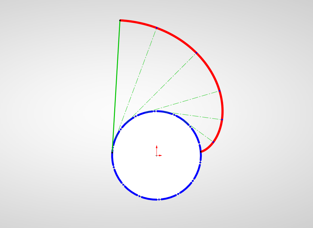
To help visualize this, take an object with a constant circular cross-section (i.e., a cylinder) and imagine winding a length of string tightly around it. Next, imagine unwinding that string while keeping it taught. The curve traced out by the free end of the taught string as it’s unwound is an involute of a circle. We can see this represented in a SOLIDWORKS sketch in the next image. The blue circle is the “parent” shape, the green lines represent the taught “string” as it’s unwound, and the red curve is the involute curve traced out by the free end of the “string”.
While the “string” analogy we just saw gave us a decent idea of what an involute is, involutes are more generally defined by a set of parametric equations. We don’t discuss the derivation of the equations here as it is outside the scope of this blog post, but we will be using them to generate our gear geometry. Thankfully SOLIDWORKS gives us a straightforward way to do this with the “Equation-Driven Curve” tool. If you are unfamiliar with equation-driven curves, you can get a good overview of how to use them in our blog post “How-To Use Equation Driven Curves in SOLIDWORKS”.
But before we do that, let’s first look at the driving parameters and equations that will define the involute curve and ultimately the spur gear geometry overall.
Driving Parameters and Equations of an Involute Spur Gear
As you know from the two preceding blog posts, spur gears are standardized parts whose geometry is driven by certain parameters. You need to set up these parameters as inputs for the model using global variables. Note that for this blog post, I’ll be working in the IPS (Inch, Pound, Second) system of units. This means that the diametral pitch will be used to define the spur gear instead of the metric module. With that in mind, the three main spur gear parameters are:
- 𝐷𝑖𝑎𝑚𝑒𝑡𝑟𝑎𝑙 𝑝𝑖𝑡𝑐ℎ, 𝑷
- 𝑃𝑟𝑒𝑠𝑠𝑢𝑟𝑒 𝑎𝑛𝑔𝑙𝑒, 𝜶 (𝑑𝑒𝑔𝑟𝑒𝑒𝑠)
- 𝑁𝑢𝑚𝑏𝑒𝑟 𝑜𝑓 𝑡𝑒𝑒𝑡ℎ, 𝒛
We will also use these secondary parameters as inputs to define the gear thickness (face width) and borehole size:
- Face width, s (in)
- Bore diameter, db, (in)
Next, you need to implement the standard gear equations that will take the input parameters and translate them into spur gear geometry. You can set these equations up as global variables in SOLIDWORKS as well. Note that while these standard equations are a good starting point, be sure to refer to the applicable standards and documentation when designing your gears. It may be necessary to modify certain equations to fit your specific application.
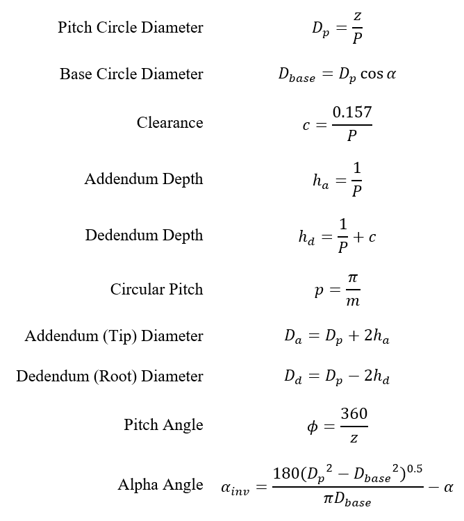
We will also make use of the two following equations to assist with the parametrization of the involute curve in SOLIDWORKS:

Note that these are standard gear equations which are also valid for metric gears with some minor modifications to make use of the metric gear module instead of diametral pitch.
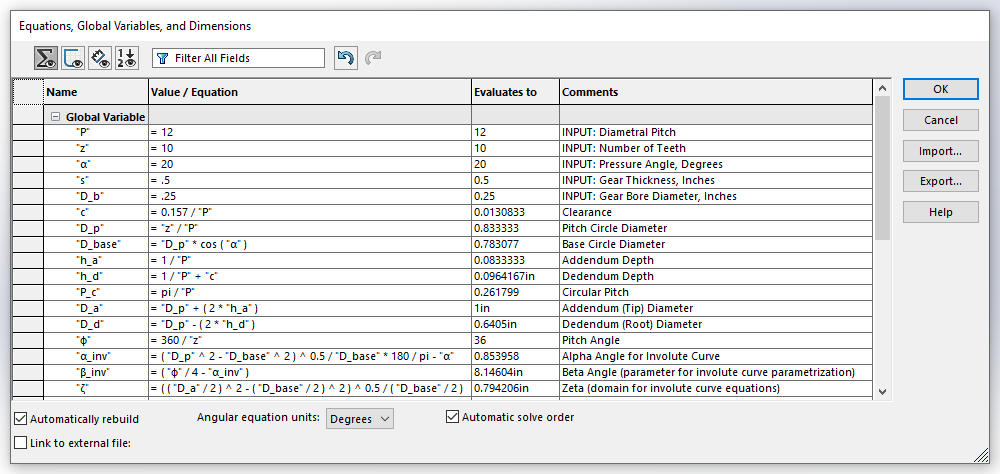
The next image shows the input parameters and gear equations implemented as global variables in the SOLIDWORKS Equation Manager.
Here the input parameters are labeled with a comment starting with the word “INPUT:”. This is not 100% necessary, but it helps us organize and quickly identify which global variables will act as inputs to our system of equations.
The values given for our input parameters in the image below are just an example, but nonetheless, they are a good starting point for building up our model. Also, note that all angles are calculated in degrees, so be sure to select “Degrees” from the dropdown at the bottom of the Equation Manager. Make sure that “Automatically rebuild” and “Automatic solve order” are checked.
Building Our Involute Spur Gear Model
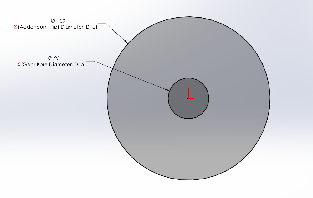
After entering the input parameters and gear equations as global variables, you can begin creating the sketches and features for the CAD model. Step one is to create a sketch for a gear “blank”. This “blank” acts as the base feature that we will then “cut” our gear teeth into. The sketch consists of two concentric circles centered at the origin. Dimension these two circles using these global variables:
- Gear bore diameter, D _ b
- Appendum (Tip) diameter, D _ a
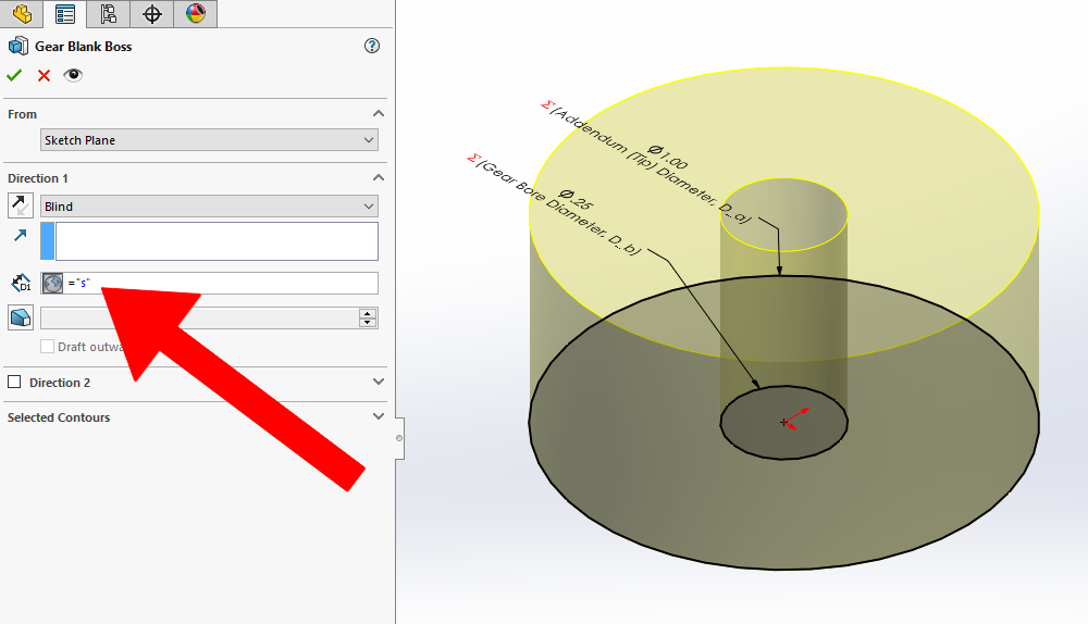
Next, create an extruded boss/base from the gear blank sketch. Set the depth of the extrude to the gear face width/gear thickness global variable, s
Create a second sketch on the same plane as the gear blank sketch. This sketch will define the contour for the tooth profile cut. Start by sketching three concentric construction circles centered at the origin. Dimension each of the circles using these global variables:
- Pitch Circle Diameter, D _ p
- Base Circle Diameter, D _ base
- Dendendum Circle Diameter, D _ d
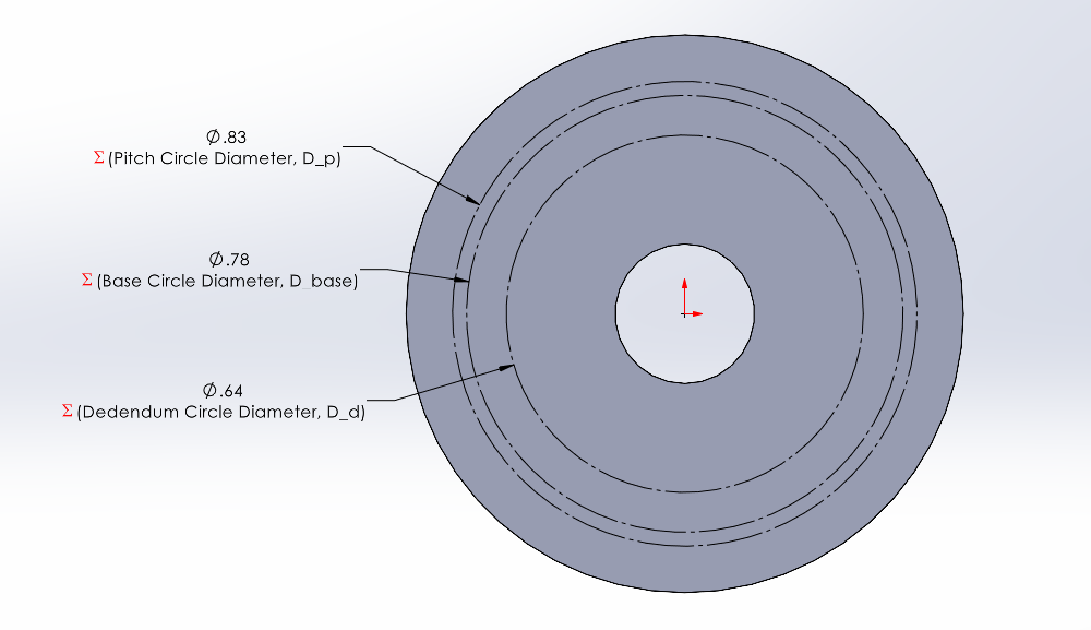
You can now add the involute curve to the sketch that will define the gear tooth profile. This involute curve is given by the following set of parametric equations, from t1 to t2:

Note that this set of equations represents a single involute curve or, in other words, one-half of the curvature of the gear tooth profile. You can sketch just one-half of the profile here (which you will later mirror) to improve the rebuild time of the model.
Select the “Equation Driven Curve” tool and then select the “Parametric” option. Enter the set of parametric equations into the Equation Driven Curve property manager as shown in the next image. In the graphics area, you should see a preview of the curve going from the diameter of the base circle, “D_base”, to the outside edge of our gear blank extrude (a.k.a. the addendum or tooth tip diameter, “𝐷_𝑎”). Hit “OK” in the Property Manager to create the curve.
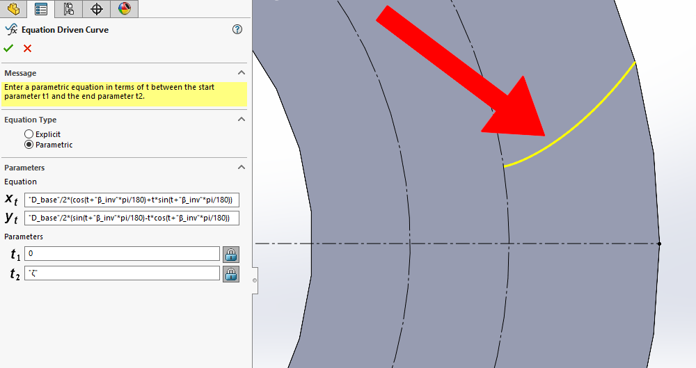
Congratulations! You have just inserted the involute curve that will define the gear tooth geometry! Add a “Fixed” relation to the curve to fix it in space.
To finalize the tooth profile and create a closed contour, add the additional lines, arcs, and relations to the sketch as shown in the next image. For reference purposes, the involute curve is shown in red, the rest of the contour is shown in green, and construction geometry remains shown in black. The two straight lines in the closed contour are coincident with the sketch origin—in other words, they are radial to the center of the gear.
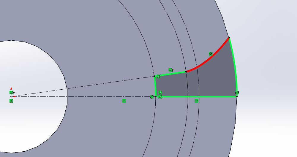
Use the closed contour you just sketched to create an extruded cut with a “Through All” end condition. This will cut away one-half of the gap between two individual gear teeth from the gear “blank”.
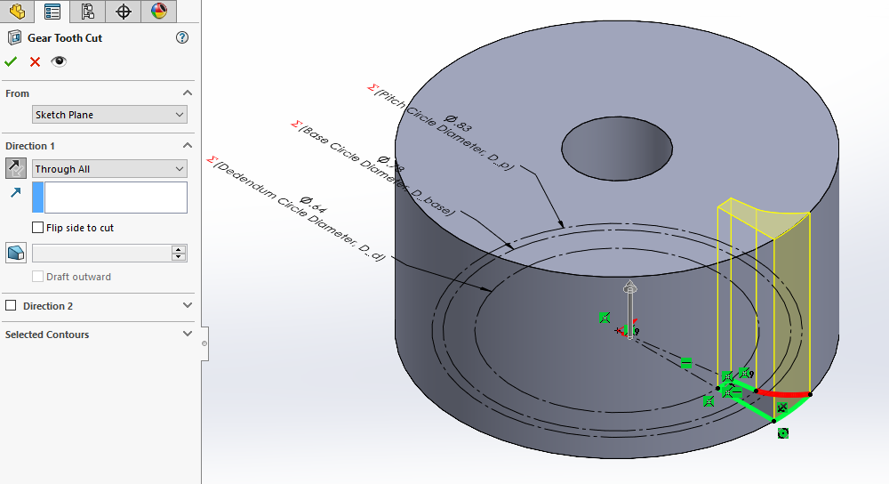
Pattern the extruded cut across the planar face of the cut itself using the “Mirror” tool with the “Geometry Pattern” option checked. With this mirror feature, you have now modeled the initial cut between two individual gear teeth.
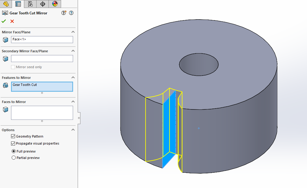
Optionally, add both root and tip fillets to this initial cut as shown in the next image. In the example here, I use the clearance global variable, “c”, as the radius for both the root and tip fillets. This choice is somewhat arbitrary, but it allows the fillet radius to scale with gear size. For traditional gear manufacturing methods, these radii are often determined by the manufacturing process itself.
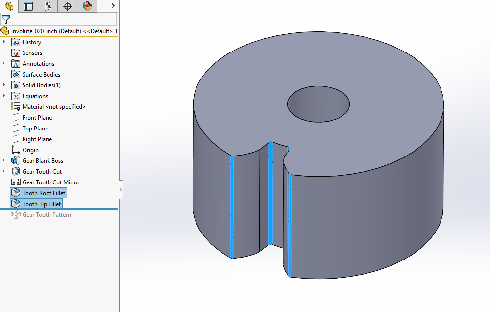
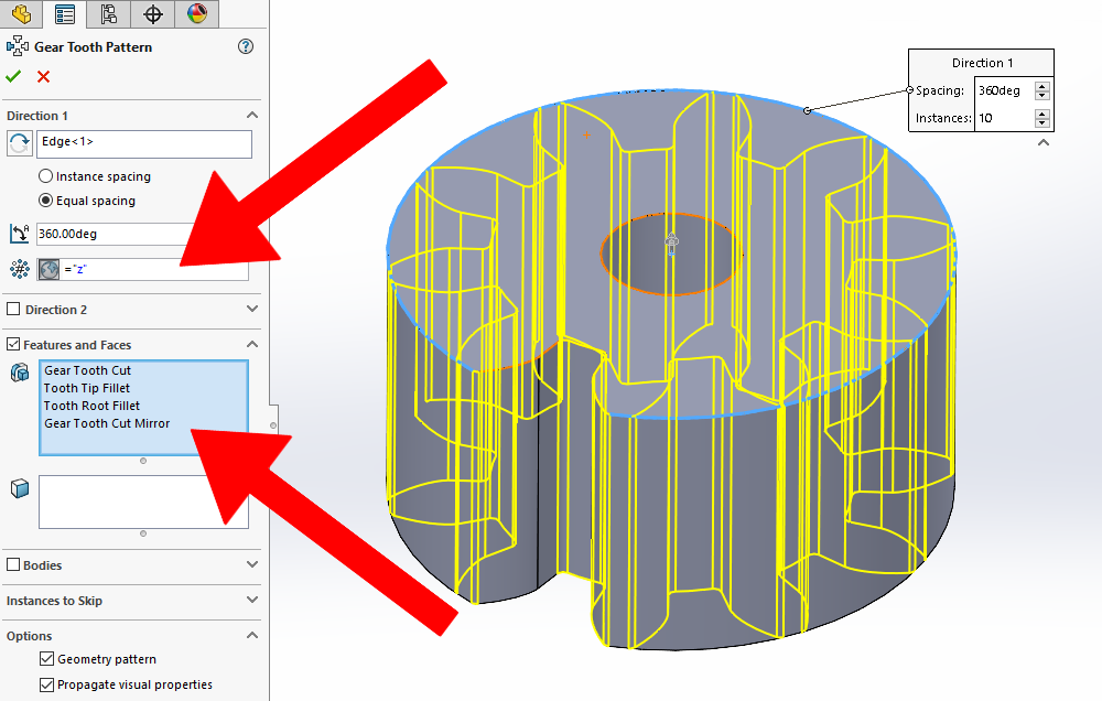
The last step in the modeling process is to pattern these features around the entire gear using the “Circular Pattern” tool. Set the circular pattern to “Equal Spacing” over a total angle of 360 degrees and the number of instances set to our global variable for the number of teeth on the gear, “z”.
Once the circular pattern has been added, you now have completed the dynamic model for the involute spur gear with accurate tooth geometry!
Next, we’ll try varying the input parameters to see how it affects the model.
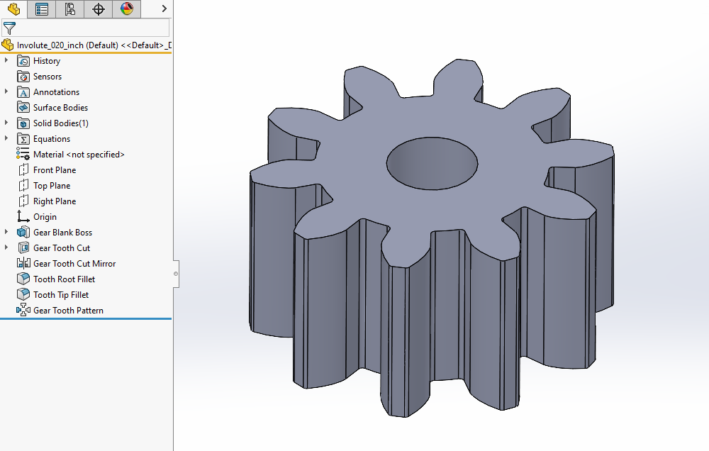
Using Our Gear Model to Size Different Gears
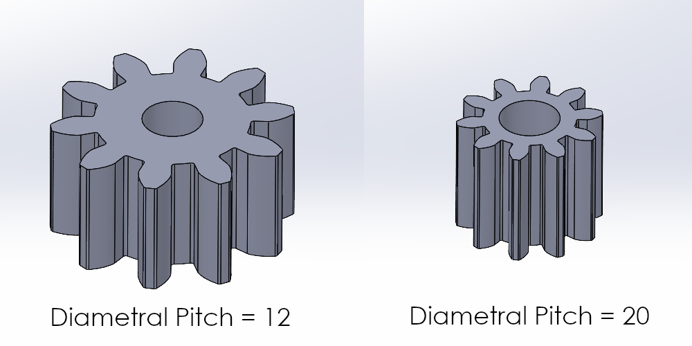
One of the great things about using this method to model our involute spur gear is that the model is dynamic. Because of how I advised setting up our global variables, equations, sketches, and features, you can generate many different-sized gears with just this one model. All you need to do is update the values of the global variables previously commented with “INPUT:” in the Equations Manager.
When we do this, SOLIDWORKS uses the standard spur gear equations entered to calculate the remaining global variables, redraw the involute curve, and update the model geometry automatically.

Therefore, thanks to the built-in feature in SOLIDWORKS to control model geometry with things like global variables and equation-driven curves, you can very easily generate many different-sized involute spur gears that are true to form. The image below highlights this behavior with a change in a single input parameter, in this case, the diametral pitch global variable, “P”, to generate a completely different-sized gear.
Limitations of Our Involute Spur Gear Model
While this method of modeling a spur gear is certainly useful, the model is not guaranteed to work for every possible combination of input parameters. Take care to avoid using input parameters that would create invalid CAD geometry or that don’t make sense for the geometry of a spur gear.
It’s also important to keep in mind that the scope of this blog post is limited to the model itself.
I haven’t discussed how to design a spur gear here, just how to model one in SOLIDWORKS using a few input parameters. There are many other application-dependent design considerations to take into account when it comes to the design of an actual spur gear such as:
- Undercut
- Profile shift
- Topping
- Root relief
And, as with any engineering design, the spur gear parameters should be determined through your own trade studies, analysis, and testing.
Nevertheless, once you have done the engineering to establish the design parameters, the spur gear model discussed here can serve as a great baseline model to build from.

Improving System Performance of our Involute Spur Gear Model
One last thing to consider is how the spur gear model affects system performance.
As you’ve seen thus far, SOLIDWORKS must do a fair bit of calculation to be able to build the CAD geometry from the input parameters. These calculations unfortunately lead to longer rebuild times.
While these rebuild times can be relatively minor for a single spur gear model, they can add up quickly as your gears and assemblies become more complex.
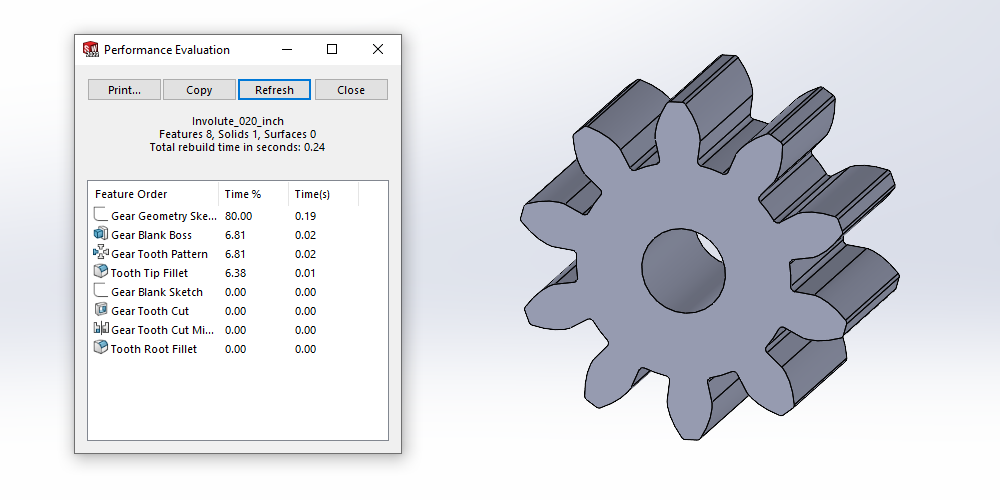
Using the SOLIDWORKS “Performance Evaluation” tool, you can see that the majority of the rebuild time comes from the calculation of the involute curve itself. In the next image, you can see that, in this case, 80% of the total rebuild time comes just from the sketch containing our involute curve.
To help mitigate this increased rebuild time, it’s best practice to prevent the individual features within the model from being rebuilt once you’ve finalized its main geometry.
If you want to maintain the features and equations used to generate the gear model without having them rebuilt, you can make use of the “Freeze Bar” in the Feature Manager design tree to help decrease rebuild time.
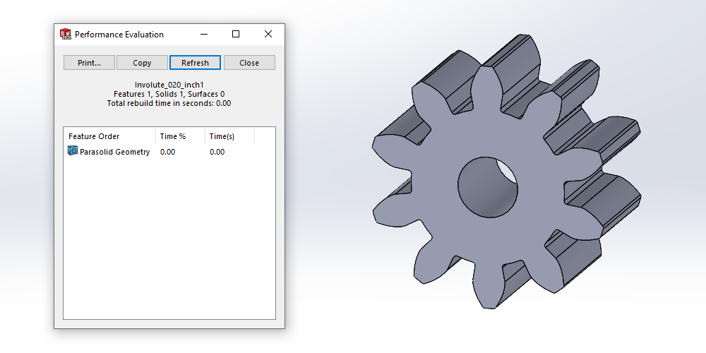
Alternatively, if maintaining those equations and features is unimportant for your final model, you can minimize rebuild time by saving it in a “dumb” or neutral file format, such as a Parasolid.
Using the Parasolid method, you can again open the “Performance Evaluation” tool and see a clear difference in the rebuild time between the two formats. It drops from around a quarter of a second (0.24s) for the dynamic model to a negligible amount (showing as 0.00s) for the Parasolid.
Closing Thoughts on Spur Gears in SOLIDWORKS
Many applications do not require accurate involute gear geometry. You should always analyze your use cases to see which option would be the best fit. If you have a use case where the approximate geometry of the Toolbox spur gear is sufficient, then you should absolutely make use of it. But in use cases where accurate involute geometry is required, the method I’ve discussed here gives you a great baseline for your designs.
Hopefully, this series of blog posts has helped you learn a little bit about using spur gears in SOLIDWORKS. Whether it’s via the SOLIDWORKS Toolbox or using the method I’ve discussed here in this final blog post, you should now have multiple ways to easily insert spur gears into your assemblies.
Keep in mind that the SOLIDWORKS Toolbox spur gear component is often easier and more efficient to use.
For convenience, here are the two previous posts covering spur gears in SOLIDWORKS:
Spur Gears in SOLIDWORKS Part 1: How to Quickly Include Spur Gears in Your Assemblies
Spur Gears in SOLIDWORKS Part 2: How to Determine if the Toolbox Spur Gear Component is a Good Fit.
As always, if you have any questions, be sure to reach out to us! Contact us at Hawk Ridge Systems to discuss how the suite of SOLIDWORKS software can help improve your workflows and products.
