BACKGROUND
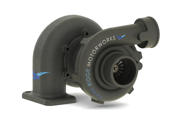
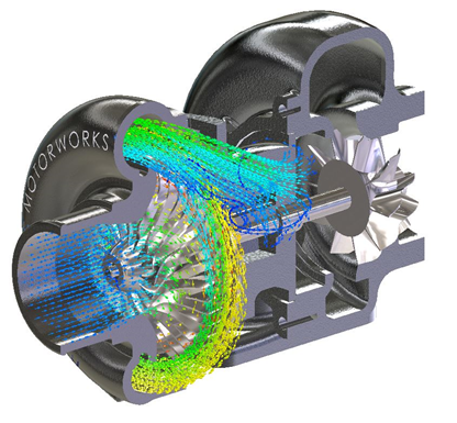
Let’s first talk about the basic functionality of a turbocharger. Aside from sounding cool, the main goal of a turbocharger is to increase the pressure of the air that is supplied to the engine’s combustion chamber. By compressing the air, we are essentially increasing the volumetric concentration of oxygen which enables you to inject more fuel into the combustion chamber and results in more mechanical power. This explains why you can have a 2.0L engine capable of producing 300 HP (which is impossible for a naturally aspirated engine of the same size).
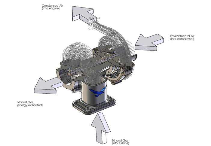
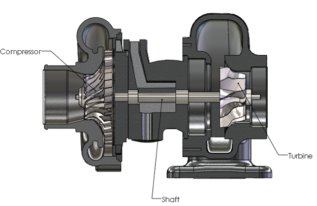
The process is powered by feeding exhaust gases from the engine into the turbine casing. The heat of the exhaust gasses causes expansion of that gas once it is released from the combustion chamber. The turbine casing funnels the gasses to a turbine impeller. The impeller extracts energy from the gasses and converts it to rotational momentum which spins the impeller (which explains why the exhaust gasses are cooled after the process).
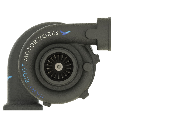
The turbine impeller is connected to a shaft which has a compressor impeller at the opposite end. Since there is a direct connection, the compressor and turbine spin at the same speed.
Once the compressor starts spinning fast enough it sucks in air, compresses it, and feeds it to the engine combustion chamber.
It is important to note that the rotational speed is controlled by the load on the engine. If there is more load, more exhaust gases are produced and thus the turbine spins faster. The boost in power is limited to the increase in pressure due to the compressor. In other words, in order to study the performance we will be mainly focused on the compressor.
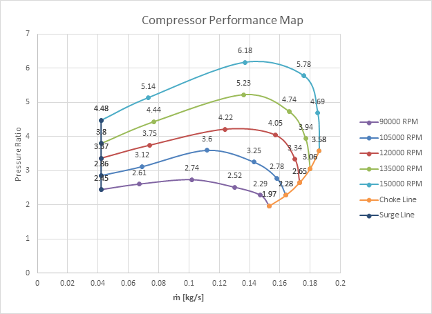
In order to get a good idea of the operational characteristics of the compressor design, it is most common in industry to develop a compressor performance map. The map, or plot, relates the mass flow rate of the gasses to the pressure ratio.
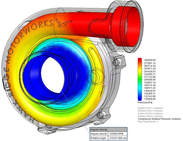
The pressure ratio (P ratio) is a simple division of the pressure of the gas at the outlet of the compressor (P out) by the pressure of the gases at the inlet (P atm), in our case it will always be atmospheric.
P ratio = P out/P atm
SET UP
Now that we have a goal in mind and a base understanding, let’s set up our problem in SOLIDWORKS.
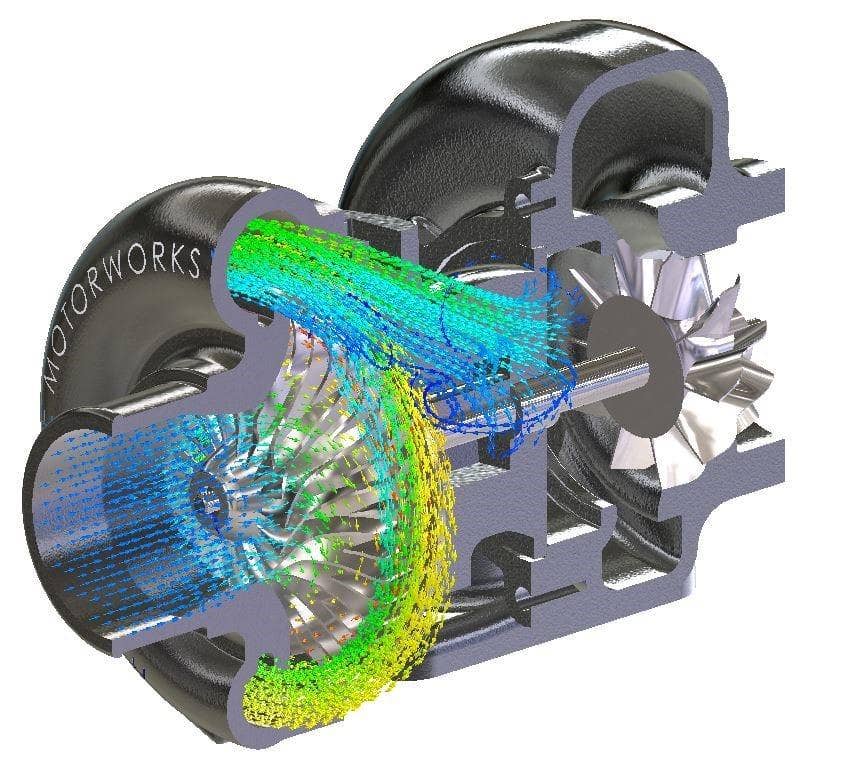
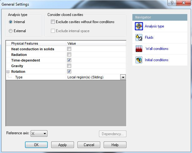
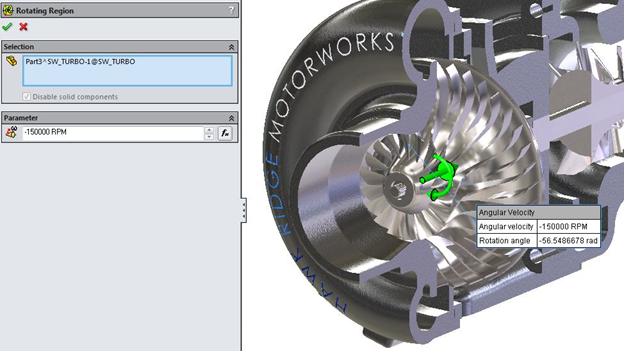
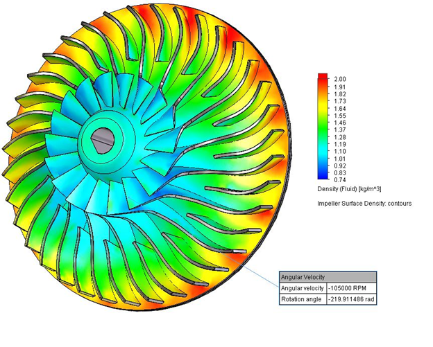
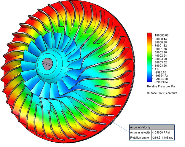
Since we are focusing on what happens within the compressor, this will be an internal analysis type. Furthermore, we have to consider the fact that the impellers are spinning. This spin is what is doing work on the flow, compressing it, so it is crucial to include it. Luckily, SOLIDWORKS Flow Simulation has the sliding mesh capability which will allow me to rotate the impeller at a specified rate.
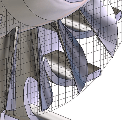
The rotating region is defined with a cylindrical part within your assembly which encompasses the rotating components (the impeller in our case).
CALCULATION CONTROL
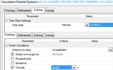
When using a sliding mesh, we must perform a transient analysis. Therefore, our Calculation Control Options must be carefully considered.
Ideally, you would need to have a time step in the inverse order of magnitude to your rotational speed (if you are unsure, allow the study to run and you will be given a suggestion pf what time step to use in the solver window). The reason for this is to ensure accuracy.
When dealing with high rotational speeds, such as in this case, the suggested time step was 3.6 x 10^(-5)s. With such a small time step, solution times were very long. I therefore upped the time step to 2 x 10^(-4)s. The added error was within 2%, which I am very comfortable with considering the time saving (and the number of iterations this analysis requires).
GOALS & CONVERGENCE
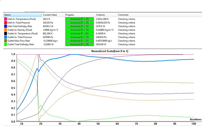
We will have to set up some Engineering Goals in order to obtain useful data and ensure that our results are accurate. Once our goals are defined, the solver will check the value obtained for those parameters and compare them with the results from a previous iteration. The discrepancy of the data will determine if we have convergence or not.
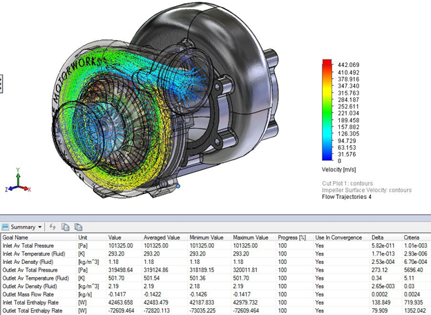
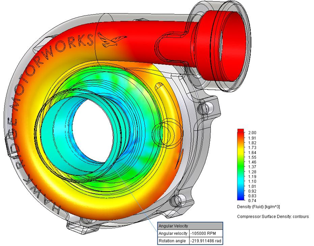
In our case the goals, measured at the inlet and outlet boundaries, are fairly straightforward. We need the pressure ratio as well as the mass flow rate. Therefore, the Average Total Pressure at the inlet and outlet and mass flow rate are essential. I also included parameters such as enthalpy, density, and temperature to get a global view of the conditions and ensure the results coincided with what I was expecting.
MESH
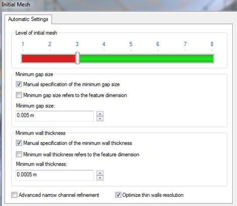
My preferred method is to control the Minimum Gap Size and Minimum Wall Thickness according to the thinnest portion of your model, and the smallest gap, respectively.
In this way, you can leave the initial slider for the mesh to be relatively coarse and still have reasonable results.
BOUNDARY CONDITIONS
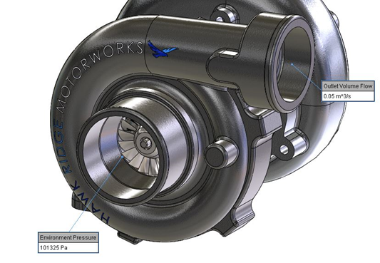
The boundary conditions need to be set in such a way that the mass flow rate and pressure ratio would not be hindered. Accordingly, I set an environmental pressure opening at the inlet, and a volumetric flow rate at the outlet.
The pressure ratio and mass flow rate trends could then be calculated by running the study and incrementally changing the volumetric flow rate until the flow was choked (constant mass flow rate).
RESULTS
| 90000 RPM | |||
| Q [m^3/kg] | P OUT [pa] | ṁ [kg/s] | P RATIO |
| 0.025 | 248059 | 0.042 | 2.45 |
| 0.035 | 264991 | 0.067 | 2.62 |
| 0.050 | 277272 | 0.102 | 2.74 |
| 0.065 | 256175 | 0.130 | 2.53 |
| 0.080 | 231672 | 0.147 | 2.29 |
| 0.100 | 199416 | 0.153 | 1.97 |
| 105000 RPM | |||
| Q [m^3/kg] | P OUT [pa] | ṁ [kg/s] | P RATIO |
| 0.025 | 291322 | 0.042 | 2.88 |
| 0.035 | 315851 | 0.069 | 3.12 |
| 0.050 | 347745 | 0.112 | 3.43 |
| 0.065 | 319499 | 0.143 | 3.25 |
| 0.080 | 281681 | 0.158 | 2.78 |
| 0.100 | 231335 | 0.164 | 2.28 |
| 120000 RPM | |||
| Q [m^3/kg] | P OUT [pa] | ṁ [kg/s] | P RATIO |
| 0.025 | 341321 | 0.042 | 3.37 |
| 0.035 | 379912 | 0.074 | 3.75 |
| 0.050 | 427811 | 0.124 | 4.22 |
| 0.065 | 410116 | 0.157 | 4.05 |
| 0.080 | 338515 | 0.170 | 3.34 |
| 0.100 | 268697 | 0.173 | 2.65 |
| 135000 RPM | |||
| Q [m^3/kg] | P OUT [pa] | ṁ [kg/s] | P RATIO |
| 0.025 | 389671 | 0.042 | 3.85 |
| 0.035 | 450019 | 0.077 | 4.44 |
| 0.050 | 530135 | 0.136 | 5.23 |
| 0.065 | 480421 | 0.166 | 4.74 |
| 0.080 | 399396 | 0.177 | 3.94 |
| 0.100 | 310935 | 0.180 | 3.07 |
| 150000 RPM | |||
| Q [m^3/kg] | P OUT [pa] | ṁ [kg/s] | P RATIO |
| 0.025 | 449932 | 0.042 | 4.44 |
| 0.035 | 520345 | 0.073 | 5.14 |
| 0.050 | 626306 | 0.137 | 6.18 |
| 0.065 | 585292 | 0.176 | 5.78 |
| 0.080 | 475414 | 0.185 | 4.69 |
| 0.100 | 362731 | 0.186 | 3.58 |
CONCLUSION
The pressure boost one should sustain when dealing with automotive engines is around 3 atm. That means we need a pressure ratio of about 4. Therefore, the optimal operational range for this turbocharger is 120000 RPM at around 0.06 m^3/s volumetric flow rate.
The design and testing has all taken place within SOLIDWORKS with the help of the SOLIDWORKS FLOW Simulation tool.
Thank you for reading this blog! You can find many more like this on our website.
