
As engineers, we dream of building complex machines, and solving critical problems that involve new ideas while following the laws and rules of math and science.
There are many factors to consider: the feasibility, the strategy, the logistics, the cost, the design concept, the manufacturing execution, and the lifecycle of the design.
We often start with a simple idea, sketch it out, and refine it into a vision that others can understand and support.
In this article, we’ll dive into a quick overview about using SOLIDWORKS for industrial equipment design and then the top 10 things I wish I had known working in industrial equipment design in the first few years of my career as a design engineer.

How SOLIDWORKS Is Integral to Industrial Equipment Design
In mechanical engineering, 3D modeling and the generation of 2D drawings are standard practices. When you think of 3D modeling, SOLIDWORKS inevitably comes to mind.
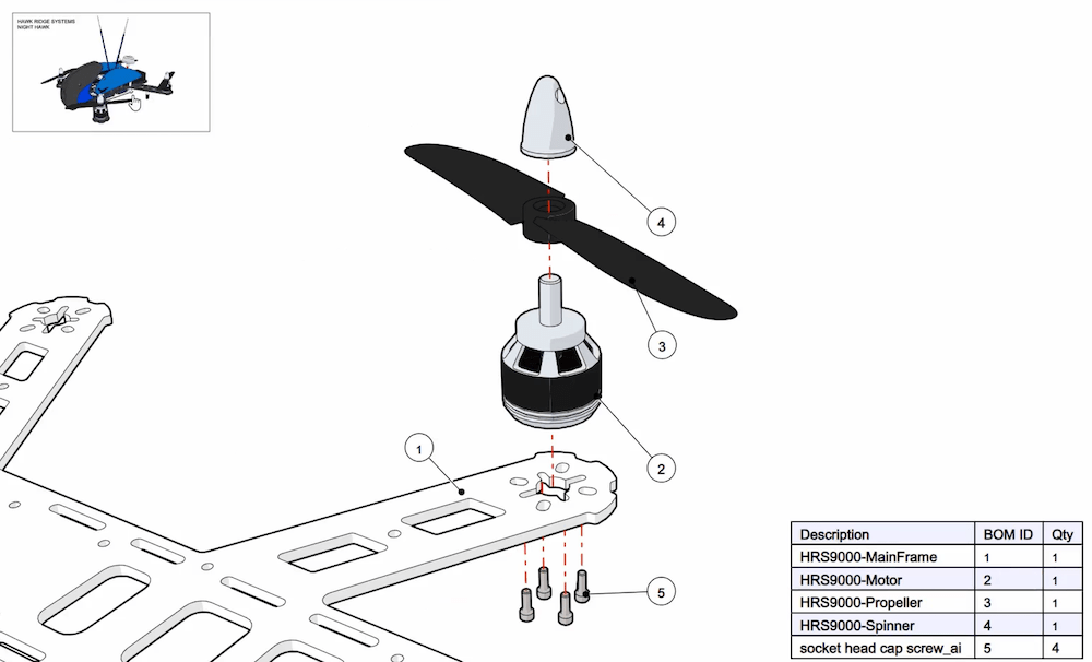
This software is integral for industrial equipment design, where parts are often created from basic shapes like circles and rectangles, extruded to achieve the desired form. An assembly model is then assembled with a generated bil of materials (BOM), detailing all necessary components.
Many designers and engineers are usually self-taught in 3D modeling, or if they are lucky, have done a course or two on mechanical drawings and drafting. Those courses typically focus on best practices for creating mechanical drawings but often overlook the nuances of effective modeling.
The reality is that within the software, there are so many different ways to do things more efficiently, consistently, practically, and conveniently.
SOLIDWORKS has a ton of options within it. It’s a part of a much bigger ecosystem of products helping engineering and manufacturing companies run their businesses more effectively and smoothly.
These various capabilities help engineers and designers, but also managers and other departments in the organization.
With that in mind, let’s explore the 10 things I wish I had known about SOLIDWORKS earlier.
1. Specialized Features for Sheet Metal Design
SOLIDWORKS provides robust tools for sheet metal design, which is crucial for industrial equipment.
Its sheet metal capabilities simplify the creation and flattening of parts, ensuring precise bends and cuts. Features such as jogs, mitered flanges, hems, and forming tools enable intricate designs.
To activate Sheet Metal options, right-click any one of the existing tabs of the CommandManager -> Tabs -> Sheet Metal.
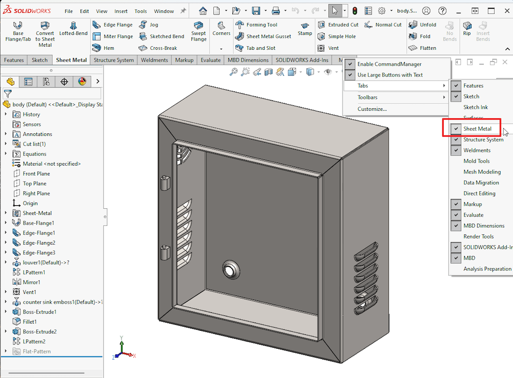
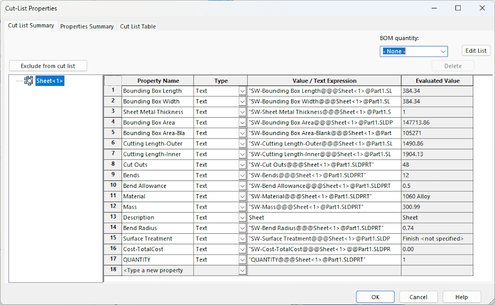
SOLIDWORKS automatically generates a cut list with critical details like bounding box size, bend radius, and gauge size. Parts designed with sheet metal features also produce flat patterns and DXF/DWG files for manufacturing.
You can learn more and get started with Sheet Metal design in SOLIDWORKS in our YouTube video.
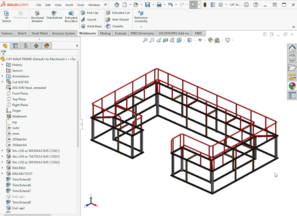
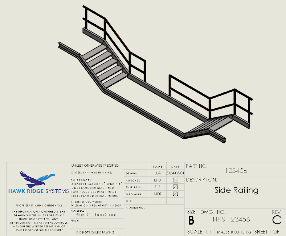
2. Tools for Structural Member Design
When designing structural components such as frames and skids, SOLIDWORKS has a dedicated set of tools for creating structural members components such as beams, columns, and channels.
There is an existing library with standard profiles and more that can be downloaded from SOLIDWORKS content.
Custom profiles can also be added. Structures can have weldments, gussets, and end caps added to the design.
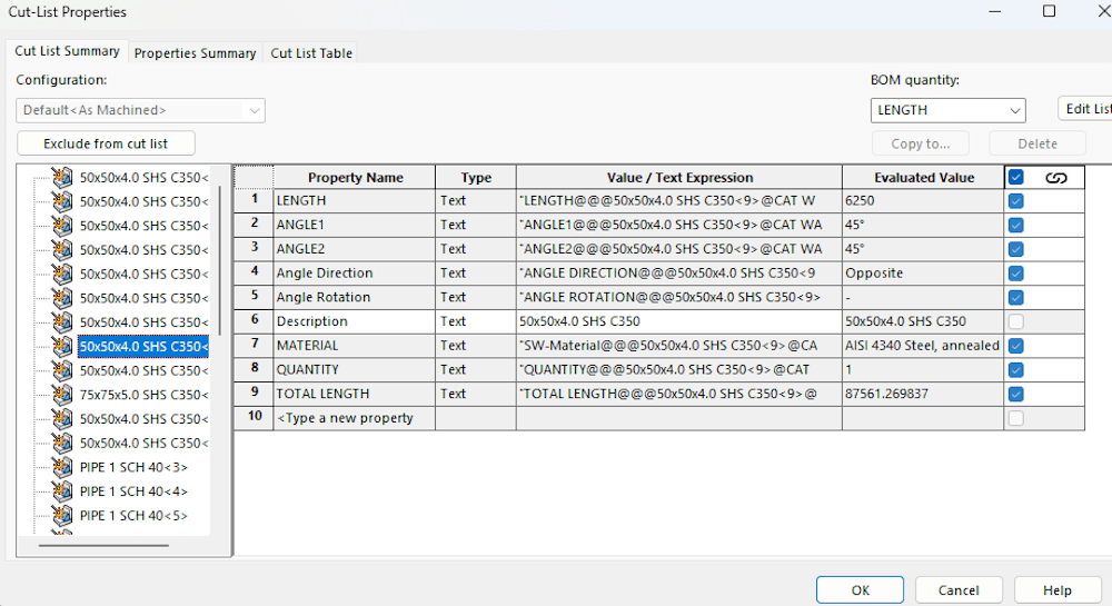
Same as sheet metal, SOLIDWORKS automatically generates a cut list with important information such as quantity of members and their associated lengths. This speeds up the design process and ensures consistency and accuracy.
There are two options for structural member design within SOLIDWORKS: one is called Weldments and, the second one, since 2018, is Structure Systems.
Here are several tutorials on these topics:
- Weldments design in SOLIDWORKS
- Structure Systems in SOLIDWORKS
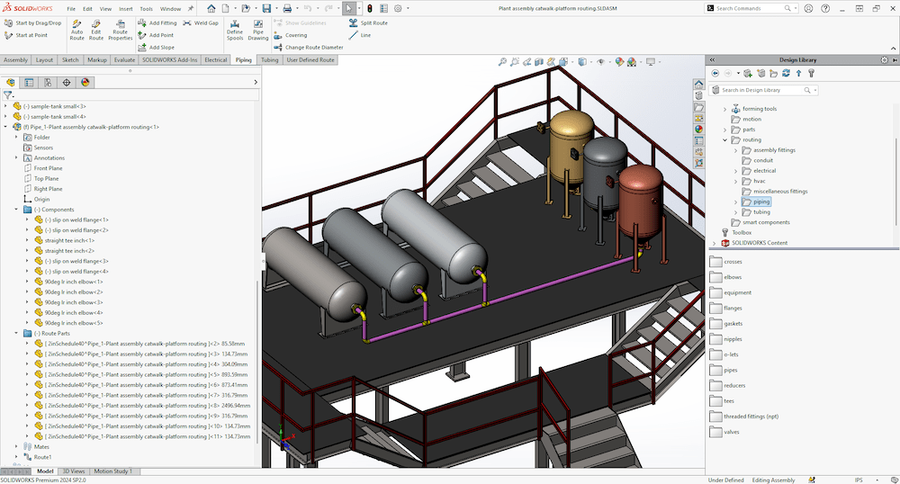
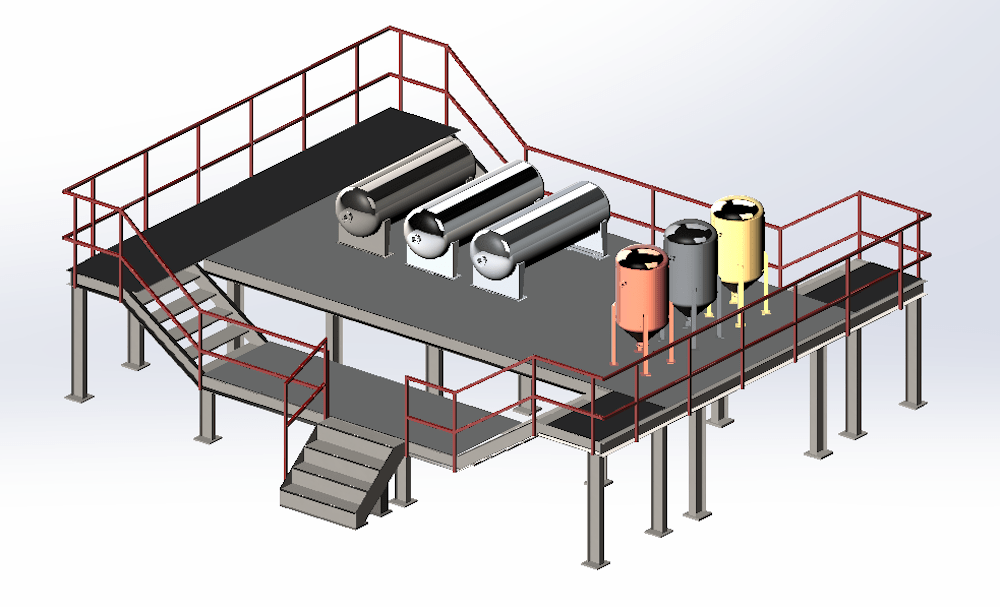
3. Add-In for Piping and Tubing Design
Piping and tubing are essential in many industrial applications, from hydraulic systems to HVAC lines. SOLIDWORKS Premium includes an add-in specifically for these tasks.
The Routing tool allows you to design piping and tubing systems (and electrical connections) with predefined components.
Routes can be created manually or automatically. An associated BOM is made and the cut lengths for all the pipe and tube in the route.
Instead of individually adding each component one at a time, this tool can significantly reduce the time spent on creating routes and can show the connections from starter to end fittings in a 3D model for better comprehension of a system.
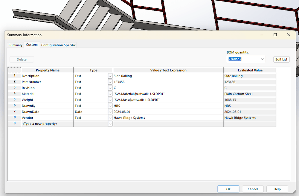
4. Metadata in SOLIDWORKS Parts
One of the powerful features of SOLIDWORKS is the ability to include metadata in part files.
Information such as description, part number, revision, designer name, material properties, mass, surface finish, drawn date, checked by, project, and other key attributes can be automatically populated into your drawings if they have been added to the part and assembly files.
The metadata can also be populated by the user, and data can be automatically inserted by SOLIDWORKS. For example, mass if a material with density is defined.
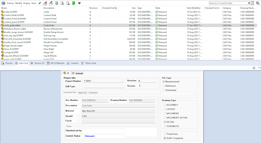
You can also use SOLIDWORKS PDM to add metadata to your parts.
SOLIDWORKS PDM helps organize, manage, and track product design data through its lifecycle. It is a centralized location for all CAD files and other documents, and it allows teams to collaborate and work together more effectively while maintaining traceability of revision and other design changes.
Wherever the information is being driven from, having metadata embedded in your SOLIDWORKS files is essential in streamlining the documentation process, reducing human error, and as a result, records are kept accurate and up to date. This ensures consistency across your design documents.
If PDM seems like too much for your needs, new purchases of SOLIDWORKS now come with Cloud Services on the 3DEXPERIENCE platform.
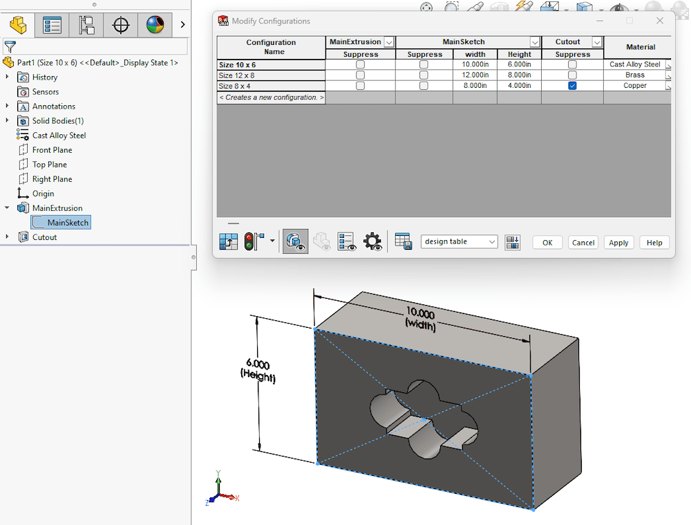
5. Using Design Tables to Configure Parts to Make Multiple Sizes & Versions
Instead of making separate parts for each version of your model, design tables in SOLIDWORKS allow you to create multiple configurations of a part or assembly by varying parameters such as dimensions, suppression, and unsupression of features/parts or materials.
This feature is a game changer when it comes to design speed and efficiency. On the fly, a user can create different versions and sizes of components quickly. It also helps simplify the management of complex assemblies.
Configurations are so powerful once you learn them that I could not imagine going back to designing parts from scratch knowing this capability.
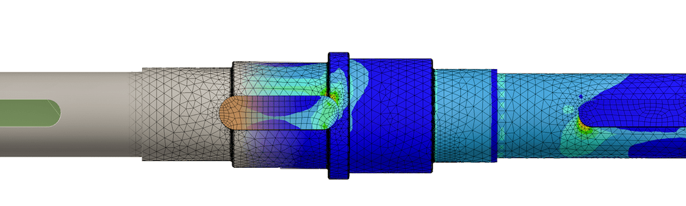
6. Running FEA and CFD Studies
Finite element analysis (FEA) and computational fluid dynamics (CFD) are crucial in verification of engineering design and intended functionality in many industrial design applications.
Attention to safety and potential critical points of failure are at the root core of designing machinery equipment. As is standard practice, an engineer will use hand calculations to verify design limitations.
Thankfully, 3D CAD software allows you to run integrated FEA and CFD tools to further assess design functionality and limitations.
SOLIDWORKS Simulation is integrated within the SOLIDWORKS ecosystem of products to analyze stress, strain, and deformation in parts and assemblies.
In addition, SOLIDWORKS Flow Simulation further expands capabilities to study fluid flow, heat transfer, pressure, and velocity changes, and other fluid dynamics-related parameters.
Both FEA and CFD are powerful in their own focused set of attributes. Together, they help designers and engineers optimize their designs, but most importantly, design products with safety and reliability.
7. Documenting Technical Manual Assembly Without Hassle
The last thing any engineer or designer wants to do is write technical manuals and assembly instructions.
Some companies may have designated technical writers for these tasks. However, even talking to technical writers, they can agree it’s a daunting task.
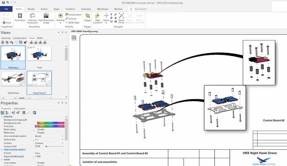
If I can find any way to make life easier on this front — sign me up. To my surprise, I learned that SOLIDWORKS Composer exists for this reason and simplifies this process substantially.
SOLIDWORKS Composer allows you to create detailed assembly documentation, animations, and interactive 3D content that can be used in instruction manuals and training materials.
The tool is a huge time saver when it comes to creating technical documentation and helps make better detailed and precise instructions for assembly and maintenance instructions for products.
8. Share Models for Review & Approval with Someone Who Doesn’t Own SOLIDWORKS
Collaborating with stakeholders who don’t have SOLIDWORKS can be challenging. Sometimes drawings are not a sufficient way of showing design detail, especially in assemblies.
In my personal experience working as a product engineer, I would spend a lot of time on the production floor with millwrights, operators, and electricians who would ask for more detail on intricate and complex systems.
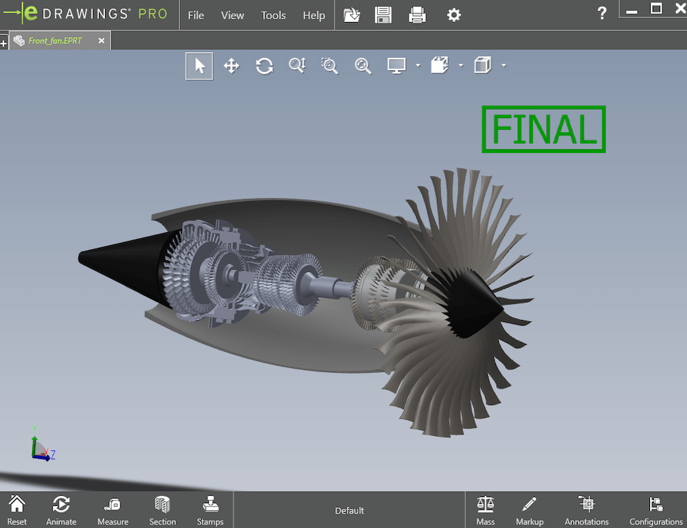
Each building bay station had a computer nearby but did not have SOLIDWORKS on it. At the time, I wish I had known we could have used a free tool called eDrawings, which can view SOLIDWORKS 3D models and other CAD files easily.
The SOLIDWORKS user can supply an eDrawings version of the model and can easily share that file with the other user for better collaboration and review of designs.
Whether it be communication between different internal departments or vendors and customers, eDrawings is a hidden gem that everyone should take advantage of since it’s free!
Having a better understanding and clarity between stakeholders is essential in streamlining feedback and necessary design changes.
9. Use Equations to Drive Model Dimensions
Models can be driven by equations! For certain industries and cases, models are made proportionally relative to the overall model size.
Equations inside of SOLIDWORKS allow you to create relationships between different dimensions, which can automatically update based on changes to other parameters.
In industrial equipment, there are codes and standards that sometimes require reinforcement at certain intervals and dimensional relations in designs. You may encounter times when you have global variables with your equations. That’s a whole another thing.
Using equations can help maintain design intent, ensure that modifications are consistently applied throughout the model, and help automate your designs.
10. The Many Features Hiding in the Command Manager
SOLIDWORKS is a powerful CAD software. One could spend a lifetime trying to master it all. The features and capabilities go beyond the basic tools visible in CommandManager.
I encourage you to explore the software’s full capabilities by digging deeper into the menus.
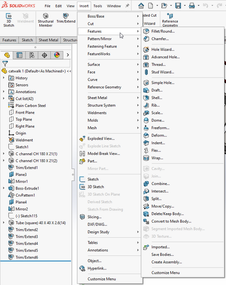
By selecting Insert -> Features, you can see the plethora of other available features in SOLIDWORKS, such as thread, advanced hole, combine, intersect, split, flex, and many others. And that’s just one set of features from the many others available under pattern/mirror, fastening feature, sheet metal, weldments, and structure systems.
One More Exciting Thing: The Latest Announcement of SOLIDWORKS Ultimate
SOLIDWORKS Ultimate was just announced in August 2024 and is the new top-tier CAD package that combines desktop SOLIDWORKS with cloud-based tools for designers, project managers, analysis, manufacturers, and other members of the company.
This new tier of SOLIDWORKS has so many products included. It’s a definite value-add for those in industrial equipment design and manufacturing.
Want to learn even more about industrial equipment design and manufacturing? Read our latest report on how to increase uptime and efficiency.

The Final Note
There is so much more to SOLIDWORKS than just 3D modeling with the most basic features. Knowing these capabilities early on can make your life much easier and more efficient when it comes to designing and manufacturing all kinds of machinery equipment.
I encourage you to explore for yourself and if you have any questions about any of the topics mentioned above, please don’t hesitate to reach out to Hawk Ridge Systems. We will be happy to answer any questions you may have.


