Industrial equipment is usually made for specific tasks and is often used in harsh and demanding environments.
From specialized robotics, generators, pumps, and compressors to various heavy machinery equipment, industrial equipment is complex but essential for efficient production and operations in sectors for energy production and generation, national defense, civil construction, mining, automation, aviation, and other manufacturing industries.

We have all seen that the industrial design and the engineering sector have been experiencing significant changes due to key factors such as Industry 4.0, real-time collaboration, sustainability, 3D printing (or additive manufacturing), automation, and integration of robotics.

Further developments in technology — such as automation, big data, and machine learning — are changing how manufacturers work and interact with customers.
In this article, we will cover how the SOLIDWORKS portfolio has helped shape and streamline the efficiency, accuracy, and flexibility of the design process for industrial equipment.
As a result, SOLIDWORKS helped companies lead to better performance, reduced costs, faster time to market, and better collaboration amongst team members.
8 Challenges Industrial Equipment Manufacturers Face in Product Development
Industrial equipment manufacturers have been challenged with unique problems in product development, from custom product design to standard products on a larger scale or one-off equipment for specialized applications.
With all these changes, the industry is required to produce products more efficiently, quickly, and cost-effectively in order to stay innovative and sustainable.
Some of the challenges faced by industrial equipment manufacturers are:
- Organizational Communication Issues: Lack of communication between internal departments as well as vendors, suppliers, and even customers.
- Miscommunication & Passing Wrong Information: If there is communication, the wrong information gets passed leading to delays in production and required rework follows. Also, having quick design revisions is not known to all team members.
- No Transparency & Understanding of Changes: Lack of visibility of changes made to design and production by all stakeholders.
- Delayed Deliveries: Long lead times on delivery of parts, products, and prototype stages of design.
- Not Considering Outsourcing: Outsourcing certain tasks that lead to longer product development times.
- Forgetting to Factor in Safety: Make sure all aspects have been considered for safety and reliability.
- Missing Requirements: Compliance with environmental and regulatory codes and bodies.
- Strained by Production Issues: Controlling costs of production, necessary repair, and rework.
Want to understand more about challenges and solutions about industrial equipment design and manufacturing? Read our latest report on how to increase uptime and efficiency.
Why SOLIDWORKS for Industrial Equipment Design?
When people hear “SOLIDWORKS,” they usually associate it with 3D modeling designs and 2D mechanical drawings.
The reality is that SOLIDWORKS is a group of products that can cover multiple areas of engineering requirements following all the way down to giving the necessary information to the manufacturing shop floor and beyond the physical factory.
Plus, SOLIDWORKS has evolved over the years with new updates. It has been leveraging the cloud-based 3DEXPERIENCE platform to provide a single, unified, collaborative environment, enabling everyone involved in product development to contribute to the innovation process.
Not only that, but we also now have SOLIDWORKS Ultimate, the latest package available.
Key Areas the SOLIDWORKS Portfolio Boost Efficiency
The key areas where the SOLIDWORKS portfolio of products can help industrial equipment manufacturers improve efficiency are:
- Standardization & Consistency: Think accurate and detailed models.
- Design Validation: Using virtual testing for stress analysis and fluid dynamics analysis can identify potential issues before physical prototypes are made.
- Reducing Costs: Having a centralized repository of files and design revisions can streamline internal processes and let you access information from a single source of truth. Think better data management like revision control, permission, and access.
- Advanced Project Management: The SOLIDWORKS portfolio can support complex product development processes and improve oversight and control over the product lifecycle.
- Streamline Transition from Design to Manufacturing: Think accurate toolpaths and optimizing machining processes.
- Produce Inspection Reports Faster: The SOLIDWORKS suite can help generate first article inspection reports more efficiently for the quality control department.
- Make technical manuals and technical assembly instructions with ease for more clarification between stakeholders and end-users
Key SOLIDWORKS Products
The key SOLIDWORKS products that are beneficial in industrial equipment design are:
- SOLIDWORKS CAD
- SOLIDWORKS Simulation
- SOLIDWORKS Simulation Flow
- SOLIDWORKS PDM (Product Data Management)
- SOLIDWORKS Manage
- SOLIDWORKS & 3DEXPERIENCE Cloud Services
- SOLIDWORKS CAM
- SOLIDWORKS Inspection
- SOLIDWORKS Composer
We’ll cover each one of these in more detail below.
SOLIDWORKS CAD
The main component of the SOLIDWORKS suite is the ability to create detailed 3D models of parts and assemblies. Its parametric design capabilities enable users to make changes to dimensions and features, which automatically updates related components.
Specific SOLIDWORKS CAD features allow for more industry specific design capabilities.
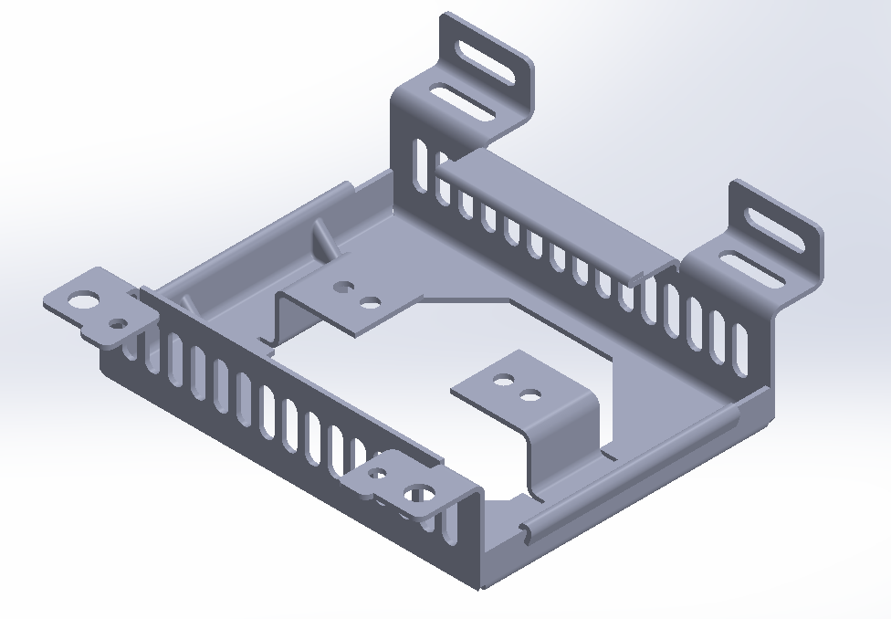
Sheet Metal Design
Sheet Metal Design includes specific tools for sheet metal parts allowing users to create and flatten sheet metal components. Bends are automatically generated, and a cutting pattern is available in DXF/DWG format so it can immediately be sent off to a waterjet or laser cutter for production.
Weldments and Structure Systems
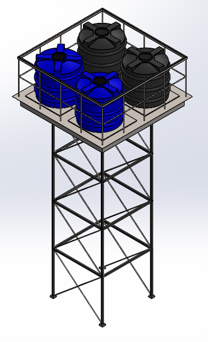
Weldments and Structure Systems include specific tools that can help generate skid frames using a library of structural beams and channels.
A skeleton sketch is used as the main driver. Sections of the sketch are selected to automatically place the structural members on. The members can be extended and trimmed relative to the members nearby. Pieces such as end caps and gussets can be added for a more complete model.
SOLIDWORKS Routing
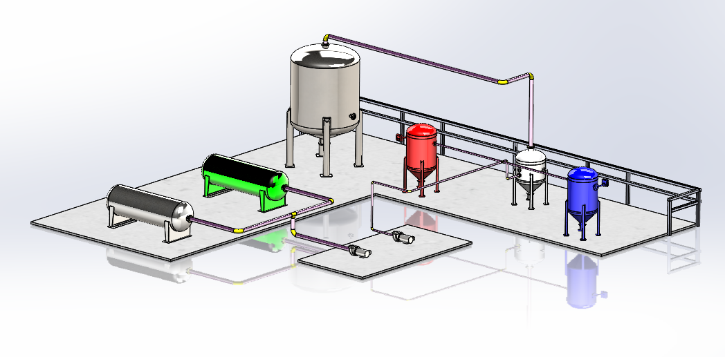
SOLIDWORKS Routing is a set of tools and features that help automate the design of piping and tubing connections. Connections of a route are added to the start and end points and a rigid or flexible path can be added between the two points.
The advantage of this method is the automation of calculated pipe lengths and automated count quantity of intermediate components such as elbows, tees, and valves.
Assembly Modeling
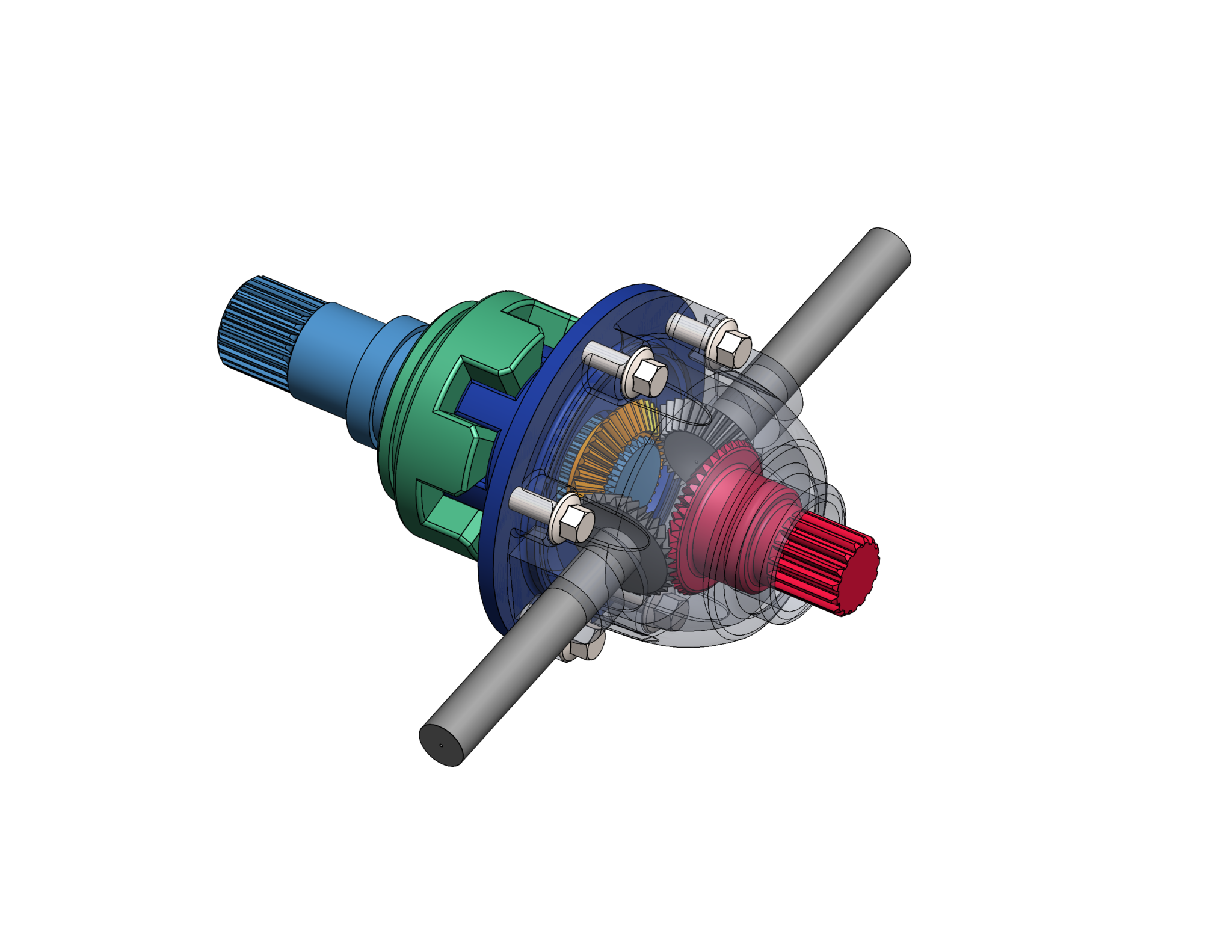
Assembly Modeling is key in industrial design to combine multiple parts together to check for fit and assembly constraints. SOLIDWORKS can help evaluate interference detection and analyze the motion of the assembled components.
Exploded views and bill of materials (BOM) can be added to the assembly to better communicate the design intent and what components the design consists of. Any changes made to the model will be reflected in the bill of materials needed for the final manufacturing and assembly.
SOLIDWORKS Simulation
One of the ways engineers validate design is using FEA also known as finite element analysis. FEA can be done with SOLIDWORKS Simulation. There are built-in simulation tools that can perform all kinds of different analyses from basic linear stresses to nonlinear.
The set of tools can also perform thermal studies, frequency studies, fatigue studies, vibrations, dynamic loading, and optimization studies to improve design requirements.
SOLIDWORKS Simulation comes in three tiers with various capabilities for various applications.
In industrial equipment, linear static and dynamic stresses along with fatigue stresses are of key significance to determine points of failure. As engineers, we don’t design for a single time use but for a specific lifecycle of a product.
SOLIDWORKS Simulation ensures design constraints are met using a virtual model before creating a prototype. As a result, lead times are reduced, and further safety measures are taken by accounting for loading scenarios.
Safety is of the utmost importance when it comes to heavy machinery design.
SOLIDWORKS Flow Simulation
Another design validation is using fluid dynamics. Also known as CFD, computational fluid dynamics can be done using SOLIDWORKS Flow Simulation.
The software is designed for analyzing fluid flow and heat transfer within and around components and assemblies. It allows users to simulate how liquids and gases interact with their designs, providing valuable insights into performance and efficiency.
The huge advantage is its fully integrated in SOLIDWORKS CAD and allows users to directly apply CFD studies to their 3D models without needing to export or convert files to another format.
Navier Stokes equations drive the math behind the fluid dynamics simulations. Internal and external studies are available for set up.
Users can run thermal studies to show how heat is transferred between solids and fluids using conduction, convection, and radiation. Users can also check for excessive heat in a system or manage cooling for electronic equipment.
Design can be optimized with various configurations of the model to choose the most effective design. Flow patterns, velocity, pressure, and acoustic levels are just some of the values that can be visualized. This can help interpret the flow data and if the design intent is made with the intended functionality.
High pressure change regions can be observed, same with areas of high velocity changes. Engineers and designers can determine if a design change is needed to change flow parameters or if the direction of flow needs to be adjusted for the desired output.
Designs of pumps and compressors are good examples of using SOLIDWORKS Flow Simulation.
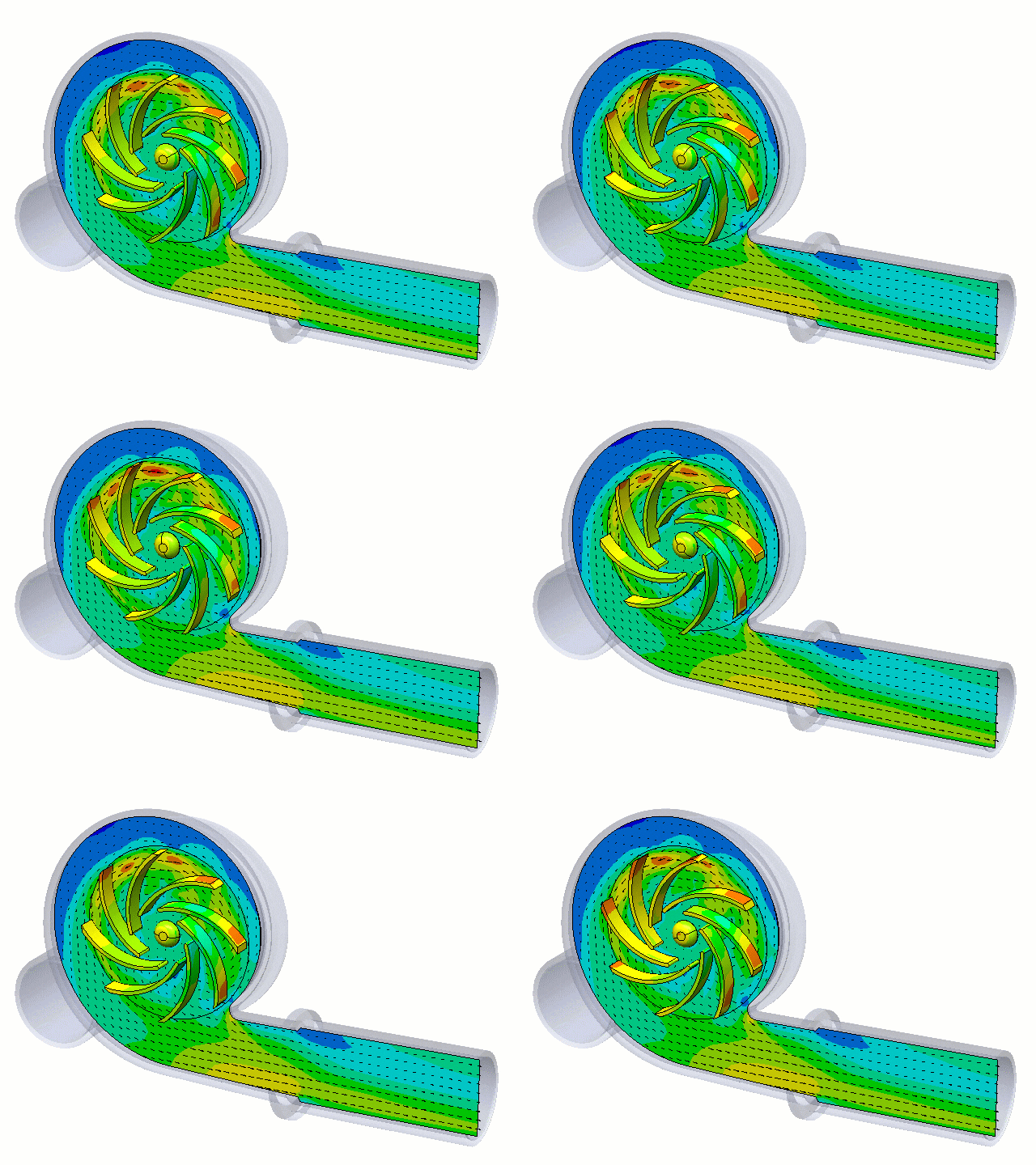
Same as SOLIDWORKS Simulation, Flow Simulation is an available add-in to SOLIDWORKS CAD (with an extra license).
SOLIDWORKS Flow Simulation can simulate all kinds of various fluid types from gases and liquids to Newtonian and non-Newtonian fluids such as slurry.
One big enhancement to SOLIDWORKS Flow Simulation in the past few years has been the capability of free surface flow (two phase flow analysis) as well as transient time simulation.
This SOLIDWORKS product is essential for engine design, heat sensitive components, turbines, electronic devices, air conditioners, heat exchangers, ventilation, and heating systems for climate control.
SOLIDWORKS Flow Simulation helps designers and engineers of industrial equipment to optimize fluid dynamics and thermal performance within their products, leading to more efficient, effective, and reliable products.
SOLIDWORKS PDM
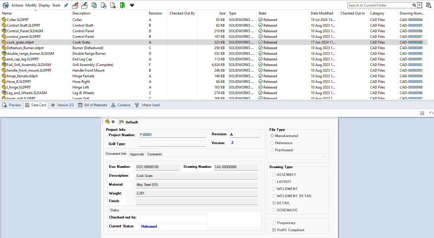
Data management is a topic engineers usually don’t like to think or talk about, but is so important for day-to-day engineering operations. Managing and organizing engineering data and documents can be tedious and frustrating. Sharing files over a sharable network or online storage solutions works for a certain period of time but problems arise in time. Duplicate files and overwriting of files can cause inconsistencies and errors.
Data management solutions are secure vaults that store all the necessary files and metadata of those files. They help with version control, access and permission control, workflow automation to control design and approval processes. Automatically it invokes collaboration amongst the users. It’s a single source of truth which also helps with traceability and auditing.
Many industrial equipment sectors follow specific codes and standards for quality and safety. Product data management (PDM) helps ensure the same procedures and steps are followed on each new design and existing design of products.
SOLIDWORKS PDM is fully integrated into SOLIDWORKS CAD and Windows File Explorer for ease of use and familiarity. The learning curve is small for the users, but there needs to be an administrator to the vault that will manage all the menus and settings such as access and permission behind the scenes.
The PDM vault can be stored on an on-premises server or hosted on a virtual server. Each setup comes with its pros and cons depending on the company’s setup and necessities.
SOLIDWORKS Manage
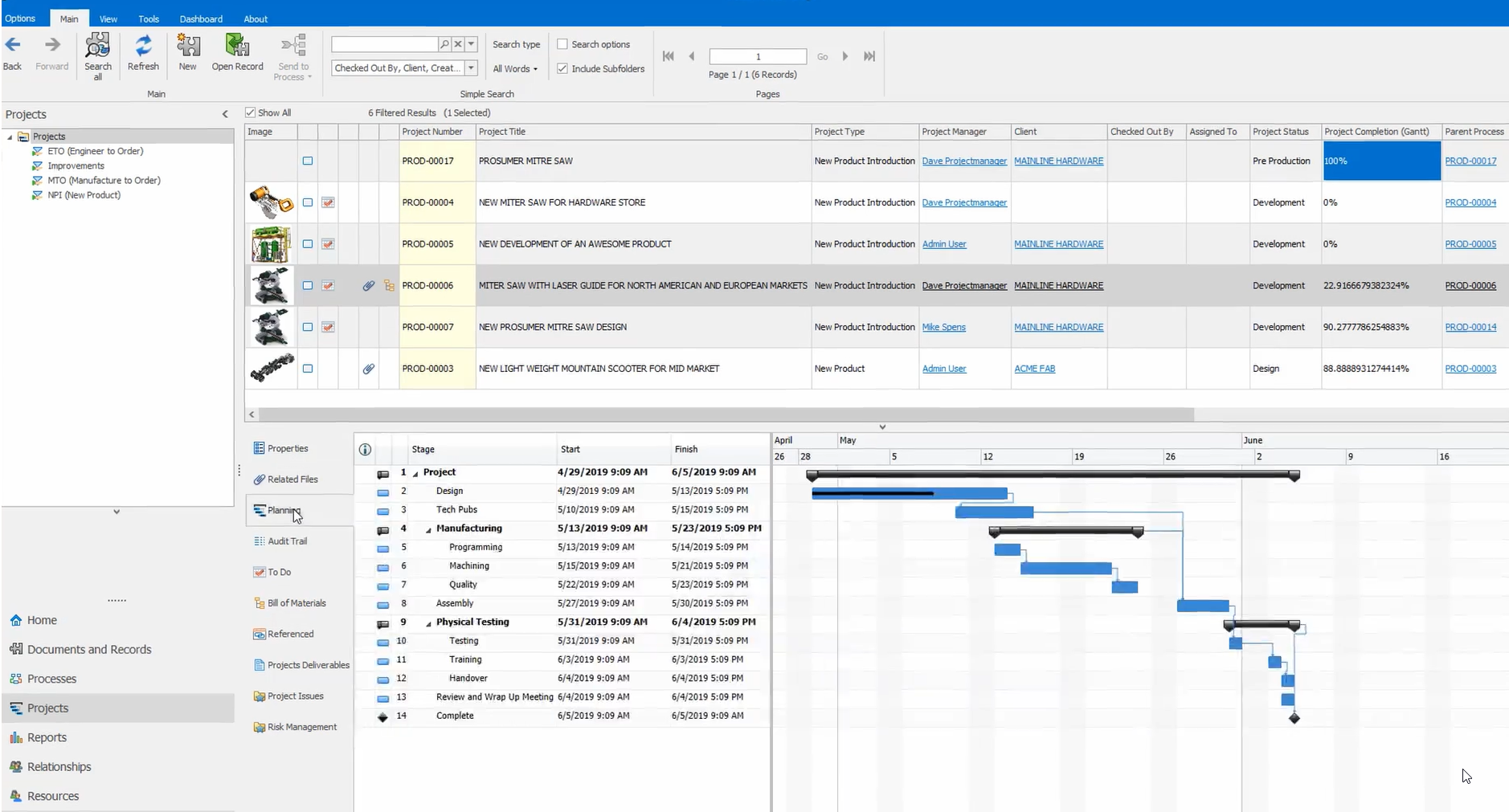
If further data control and management is needed, SOLIDWORKS came out with SOLIDWORKS Manage, which can further help with managing a wider range of documents and data types, such as project files, ECR, ECO, ECN processes, more in depth BOM management, and manipulation.
Project management tools, such as task tracking and project timelines and resource management, are also available.
SOLIDWORKS Manage helps teams plan, execute, and monitor projects more effectively. And it can integrate with other systems such as ERP (enterprise resource planning) and CRM (customer relationship management) to streamline data flow across different parts of the organization.
SOLIDWORKS API for Both PDM & Manage
Further customization for PDM and Manage is available with SOLIDWORKS API (application programming interface), which further extends the capabilities of the PDM vault and to develop custom add-ins for anything that the system doesn’t currently do out of the box.
It enables developers to interact with SOLIDWORKS to perform tasks programmatically, further increasing efficiency in executing repetitive tasks.
SOLIDWORKS & Cloud Services
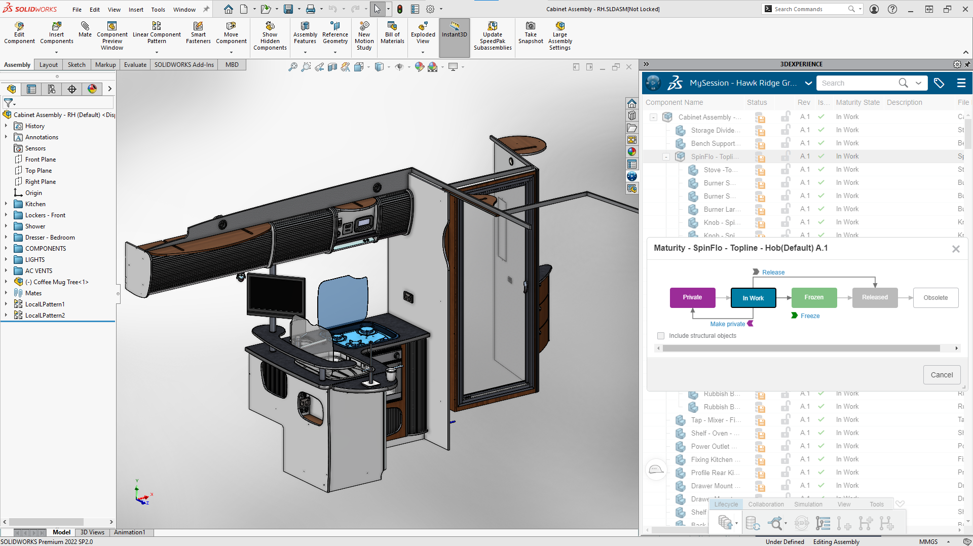
Every new purchase of SOLIDWORKS CAD now comes with Cloud Services. If PDM and Manage seem like too much for your organization, cloud services are now automatically included and at your leisure to use and take advantage of.
Think of it as a simplified PDM system that’s been already defined and configured but can be customized to a certain extent.
SOLIDWORKS CAM
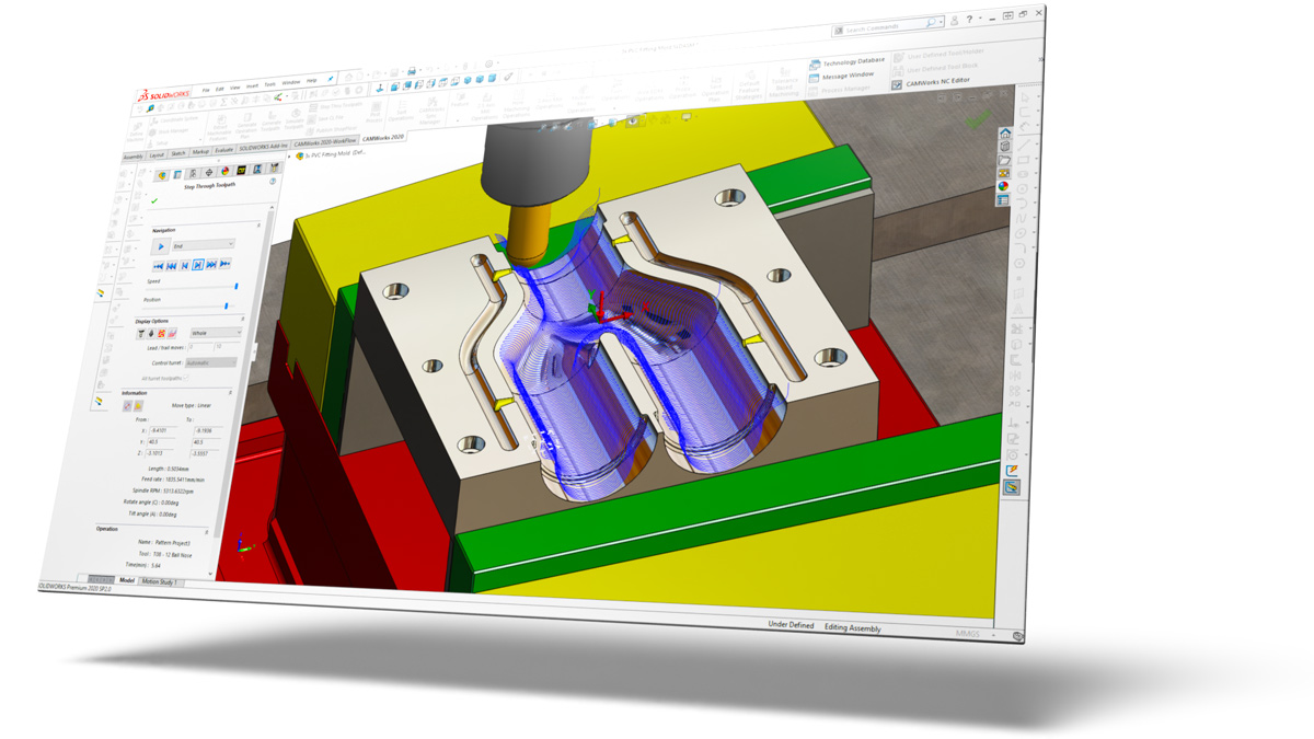
SOLIDWORKS CAM is integrated as well into SOLIDWORKS CAD to allow for seamless transition from design to production. This integration in the software makes CNC programming available to engineers and machinists alike.
All toolpaths are associated with the CAD geometry and can save the manufacturing data with the original file.
SOLIDWORKS CAM also offers Automatic Feature Recognition and rules-based programming to radically enhance manufacturing productivity.
It is already included in the SOLIDWORKS CAD license, and an upgrade to SOLIDWORKS CAM Professional is available for more enhanced post processing, 3D milling, advanced turning, and multi axis machining.
SOLIDWORKS Inspection
SOLIDWORKS Inspection is another hidden gem in the products available within the SOLIDWORKS portfolio.
Inspection enhances the inspection report generation by automating repetitive tasks, improving accuracy, and ensuring consistency in inspection reports, which ultimately contribute to higher product quality and efficiency in manufacturing.
When it comes to inspecting manufactured and assembled parts, first article inspection reports are common practices in the quality department to document accuracy and consistency of the parts and assemblies made.
In industrial equipment, parts are constantly checked for tolerance and accuracy to ensure correct sizing of parts for fit. Parts come from suppliers and vendors all over the world who may use different materials and machines with different capabilities.
Consistency must be ensured for quality to remain at the forefront of production. SOLIDWORKS Inspection allows quality control inspectors to generate first article inspection reports (FAIR) by bubbling PDF/TIFF files as well as SOLIDWORKS CAD drawings.
Bubbling dimensional characteristics and report generation are often done manually. Such a method is very prone to inconsistencies and human error. SOLIDWORKS Inspection helps automate these steps and create consistent reports using existing templates or templates can be customized to an organization’s preferences.
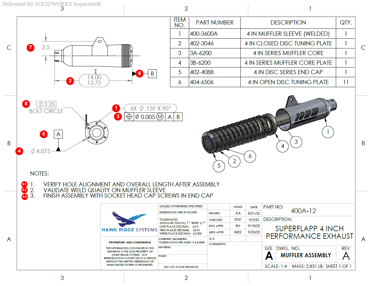
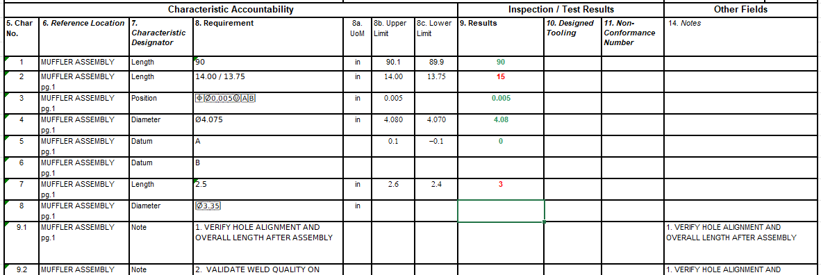
The software can measure physical dimensions and compare them against specified tolerances. This is very useful for verifying that parts and assemblies meet design specifications and quality standards. There is also SOLIDWORKS Inspection professional, which allows integration with CMMs (Coordinate Measuring Machines).
Overall, it helps manage and track inspection data more efficiently, including historical inspection results and trends. This is crucial in analyzing quality metrics and improving processes over time for quality improvement and cost reduction in potential rework costs.
SOLIDWORKS Inspection helps with regulatory compliance with industry standards.
SOLIDWORKS Composer
Industrial equipment needs to be assembled either by the company’s production team or at a customer site by specialists or the customer themselves.
Making technical documentation — such as step-by-step assembly instructions, technical brochures, technical animations, and other marketing materials — can be a challenging task if the right tools aren’t available.
However, with SOLIDWORKS Composer, this task becomes a breeze and is worth the investment.
SOLIDWORKS Composer is designed to take the 3D model and 2D images and help create visual and interactive documents that assist in communicating complex information clearly and effectively.
Using colored vector arrows, notes, and exploded and detailed views, the technical design and documentation can be set up in a wide variety of ways. From assembly instructions in a PDF manual to an animated video, the possibilities are endless.
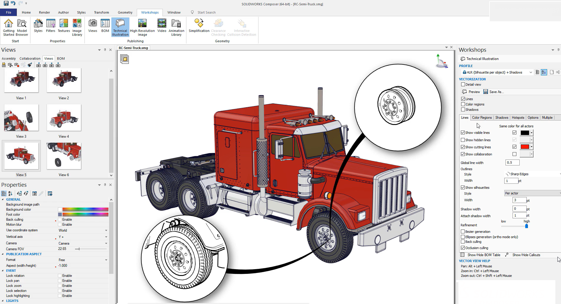
Being able to showcase how a product works or the ability to highlight specific features will make it easier for the end user to understand complex assemblies in industrial equipment design.
Misinterpretation of design or time delay waiting for clarification can be avoided by simply providing documentation that is easy to interpret by all parties. As a result, leading to better collaboration between internal staff members and outside third-party suppliers, and simultaneously becoming more efficient by eliminating the need to create separate drawings from scratch.
The key benefit is that all the data and models adjusted in Composer remain associated with the SOLIDWORKS CAD model (models can also be imported from other CAD systems), so the accuracy of the documentation stays up to date with any CAD changes.
Overall, SOLIDWORKS Composer is aimed at improving the way technical information is communicated, making it more accessible and engaging for the intended audience.
The Final Note
These are just some of the products in the SOLIDWORKS grand portfolio of offerings that could have a real benefit in the industrial equipment design and manufacturing.
With these available solutions, we as designers, engineers, machinists, technicians, machine operators, supply chain coordinators, and others have a better way of understanding the design changes and stages of the design cycle.
In turn, we do our work faster, more accurately, and effectively. With the right tools and resources to collaborate together, the efficiency of production and product development will increase and become more cost-effective, safe, reliable, and innovative.
As someone once told me, “The right tools in the right hands can turn a difficult job into an easy one.”
If you have any questions, reach out to us at Hawk Ridge Systems. We’re here to help.


