
Using Smart Components in SOLIDWORKS
Smart components in SOLIDWORKS allow frequently used components to automatically include their associated features and components in assemblies, so you don’t have to manually add them each time. The example we’ll cover in this blog will be table legs. To add a table leg to an assembly using conventional techniques, the workflow would look something like this:
- Insert table leg into assembly, and position with mates.
- Add holes to the tabletop (either with Extruded Cut or Hole Wizard).
- Add fasteners between the leg and tabletop.
While doing this once or twice is no big deal, this table leg is going to be used four times on a single table, and potentially many more times in other furniture assemblies. With smart components, steps two and three can be automated and completed with just a click or two!
Here’s how to create a Smart Component in SOLIDWORKS at a glance:
- Pick a commonly used component (it should have associated features and/or components that will be required whenever it’s used in an assembly).
- From an assembly (either one that’s already been made or a simplified mockup), go to Tools>Make Smart Component.
- Select the features and/or components to include as part of the Smart Component.
- Insert the Smart Component into any assembly.
- Right-click the component and choose Insert Smart Features.
Step 1: The Component
While this example will be using a table leg as the smart component, here are the factors to consider when determining if making a smart component is worthwhile:
- The component will be used often (either multiple times in a single assembly or in multiple assemblies, or both.)
- The component will have associated features (extruded bosses and cuts, revolved bosses and cuts, or holes.)
- The component will have associated components (fasteners for a table leg, two halves of a latch, male and female connectors, etc.)
If the component will be used relatively often, and it has features and/or components that will often accompany it, then making a smart component can be a good time investment.
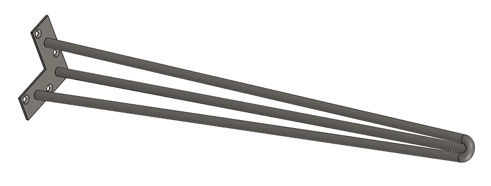
In the figure below, you can see the table leg we’ll add Smart Components to. It has a few countersunk holes for attaching to a tabletop.
Step 2: Make it Smart
The Assembly
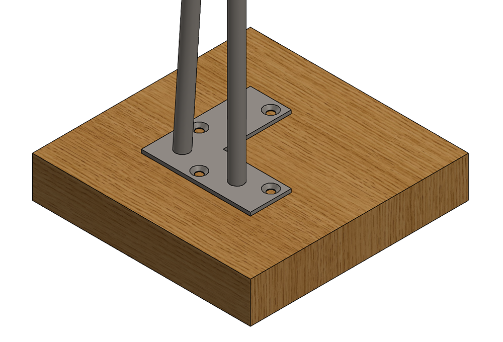
To create the smart component, the table leg must be placed in a representative assembly. While this can be done in any assembly (e.g. the full table assembly), it’s much easier to create a simplified mockup with just the essential details. In this case, an assembly was made with a small block (representing the table surface) and the table leg (Fig. 2). In the figure below, the block represents the underside of the table where the leg will attach.
Note: Making a component smart after it’s already been used in an assembly would be an example of when a mockup assembly is slower. Simply go back to the already-created assembly!
While mates are not included in the smart component, it is much easier to set up when the table leg is fully constrained to the block, so it doesn’t inadvertently move around.
Features
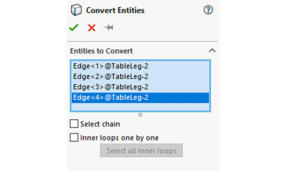
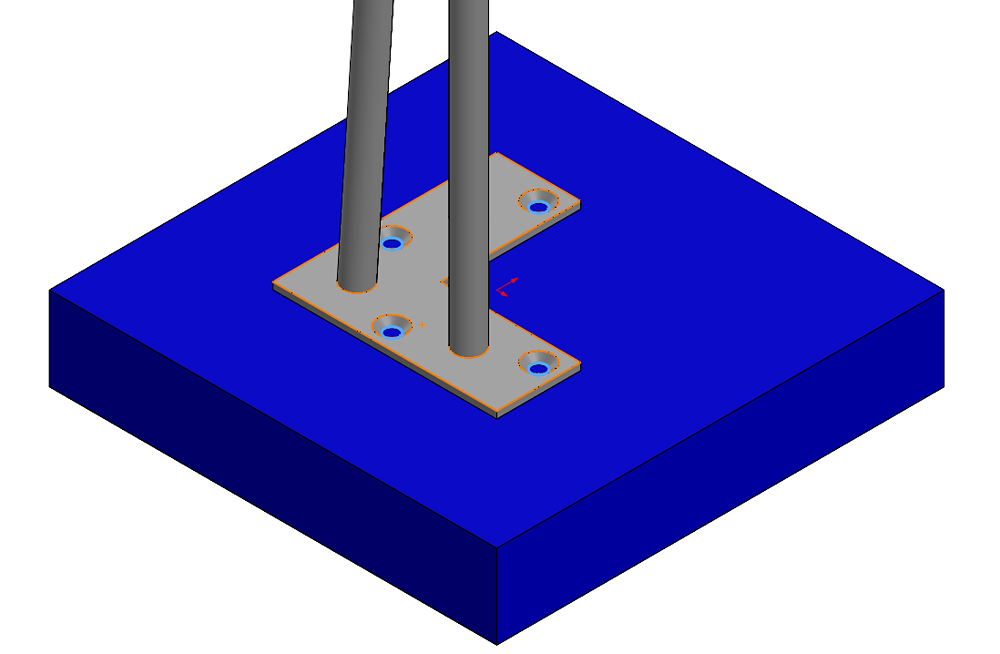
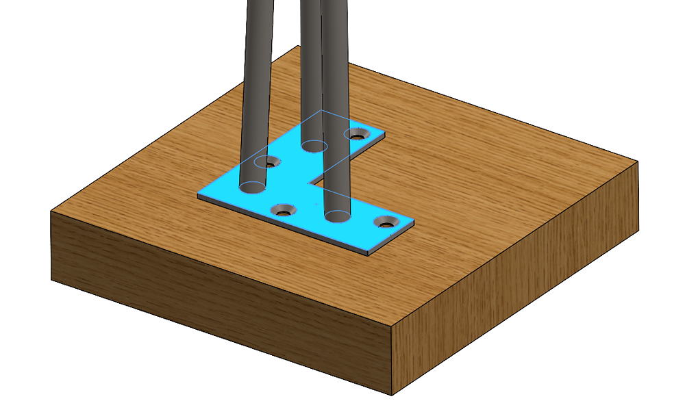
Once the leg is positioned and mated to the block, its accompanying features can be added. In this case that’ll be the pilot holes in the block that match the hole pattern on the leg. The block was edited in the context of the assembly, and the convert entities feature was used to project the four holes from the table leg onto a sketch on the face of the block. Using convert entities makes sure both the position and size of the holes are linked to the hole pattern in the table leg (See Fig. 3, Fig. 4). It also creates an in-context reference to the table leg which is required to add a feature to a smart component.
The sketch was used to create a blind cut in the block 0.5” in depth. An assembly level hole series could have also been used. As pictured below, use convert entities to line up the holes in the block with the holes in the leg. Then you’ll see the edges of the four holes in the leg highlighted.
Other Components
Other components can also be included in a Smart Component, just like features. In the case of this table leg, that will be four screws that match the countersunk holes on the leg and the depth of the holes in the block. These can be added using conventional assembly modeling techniques or using the SOLIDWORKS Toolbox (in Professional and Premium), which is shown below.
In the face that was selected above, note the holes from the previous step are here, just not visible in this current orientation in the graphic below.
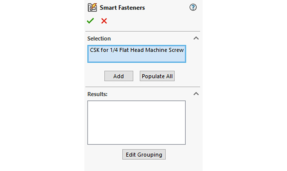
Select the face with the holes in it and click add (See Fig. 5, Fig. 6). Smart Fasteners will scan the face and find the hole wizard feature which lets it automatically determine the fastener size and type based on the definition in the hole wizard/series feature. In the figure below, transparency is added to the block for clarity.
Now the fasteners have been added (Fig. 7), the representative assembly is complete, and the leg is ready to be made into a smart component.
Smart Component
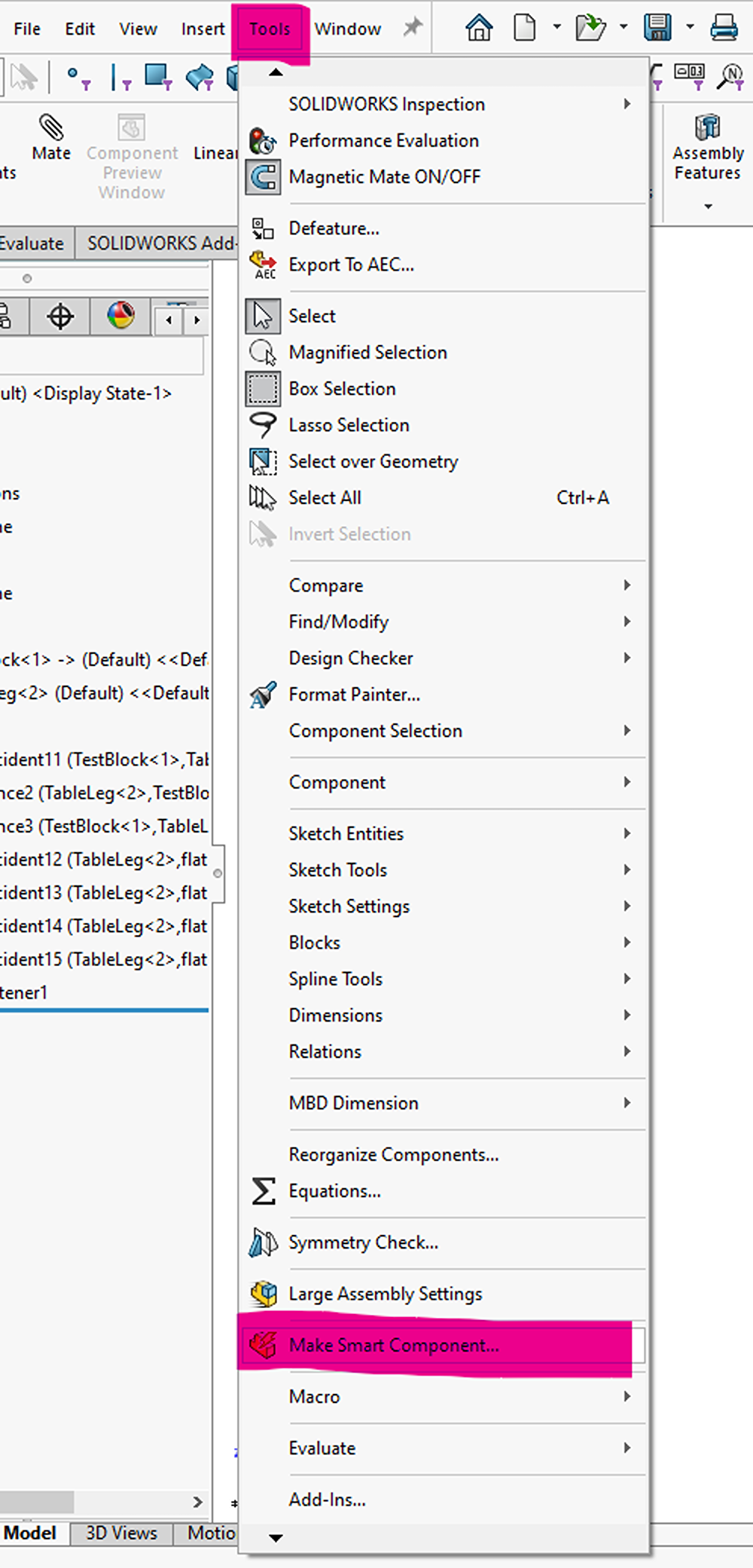
The Smart Component command is launched from Tools>Make Smart Component (Fig. 8).
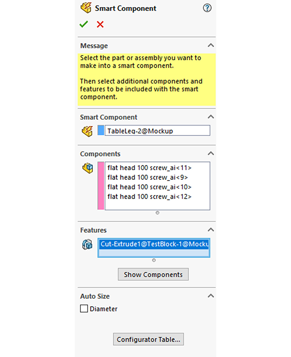
The property manager will appear on the left side of the screen (Fig. 9), with boxes to select the smart component, accompanying components, and accompanying features. They can be selected from the graphics area or by using the flyout tree. Note that while selecting features, the previously selected components (both the smart component and any accompanying components) will be hidden to make the selection easier. They can be shown again with the show components button.
Another powerful aspect of smart components is auto-sizing based on diameter, which will not be shown here. This allows things like pipe end caps to detect the size of the pipe they’re being placed on and select an appropriate matching size from their available configurations. Pictured below is the Property Manager for the Smart Component.
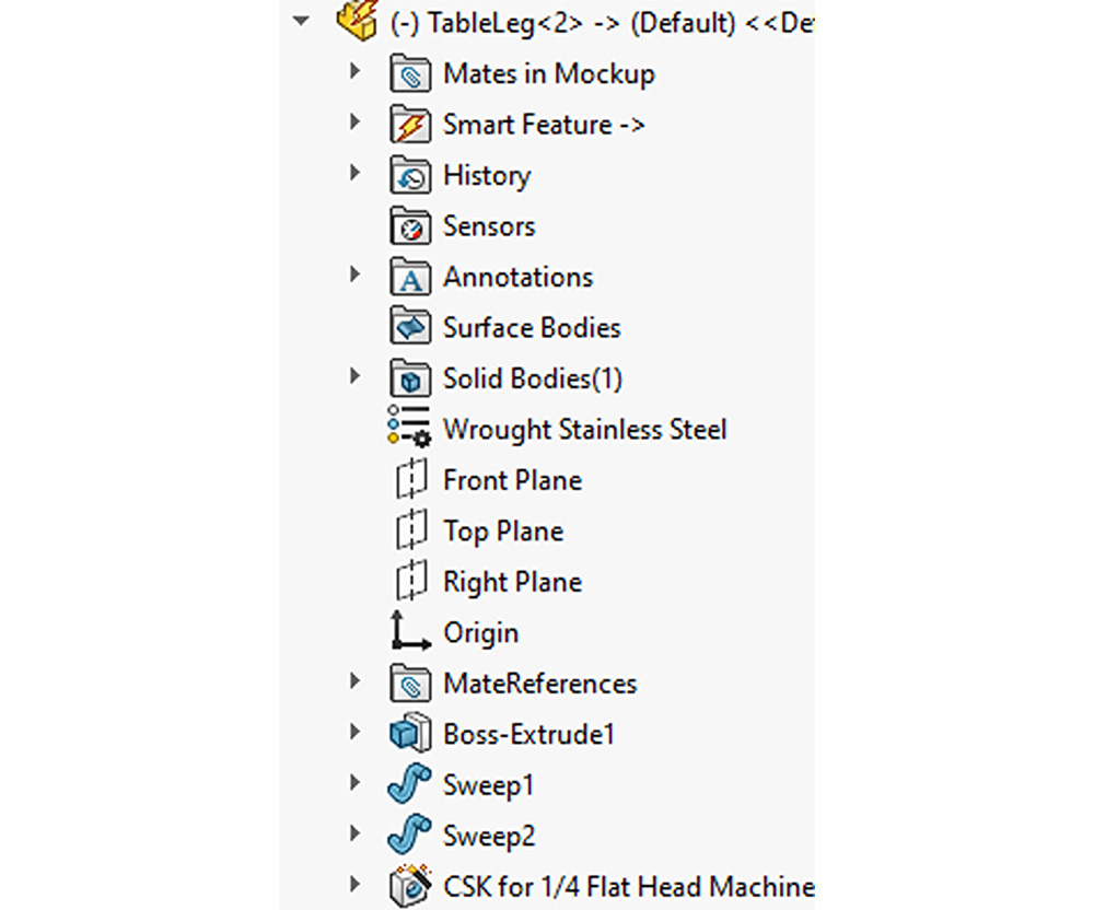
After the smart component command is complete, the table leg will show a lightning bolt by its icon in the tree and contain a folder called “Smart Feature” (Fig. 10). It is now a smart component and can be used in any assemblies! This is how the leg looks in the tree after turning it into a smart component:
Step 3: Using a Smart Component
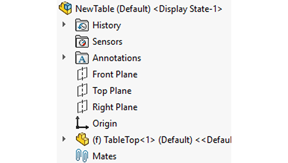
To use the smart table leg, a new assembly with a full-sized tabletop is created (Fig. 11, Fig. 12).
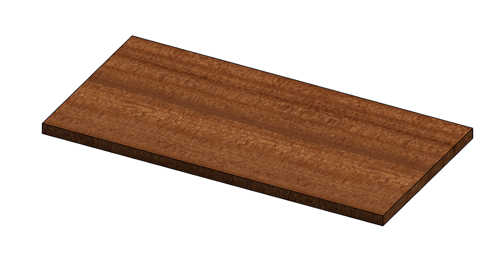
Pictured above is the tabletop we’re going to add the leg to. The leg is brought into the assembly and mated into position (Fig. 13). This table scenario is also an excellent candidate for Mate References.
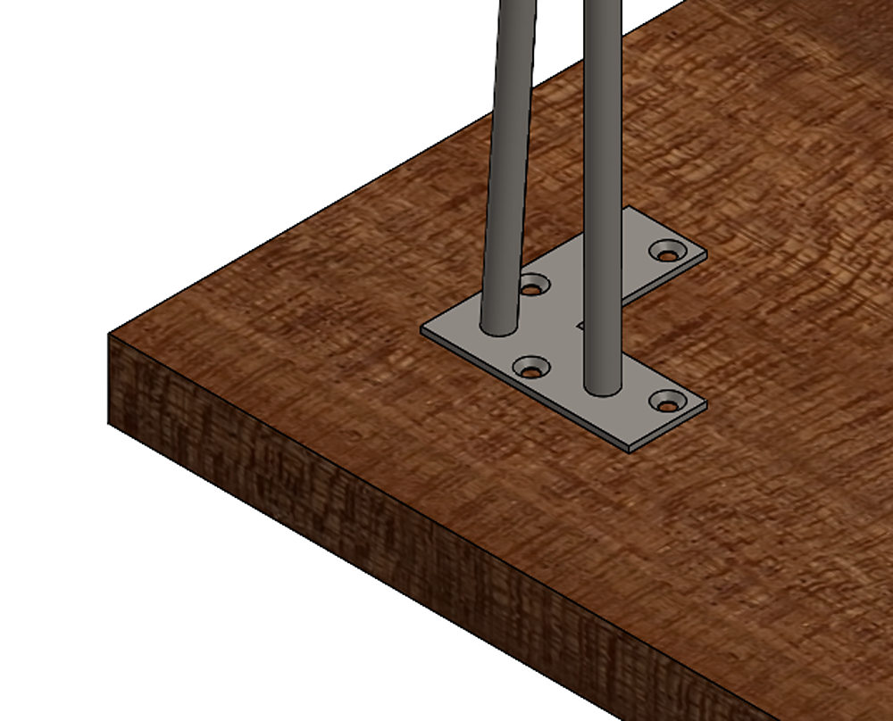
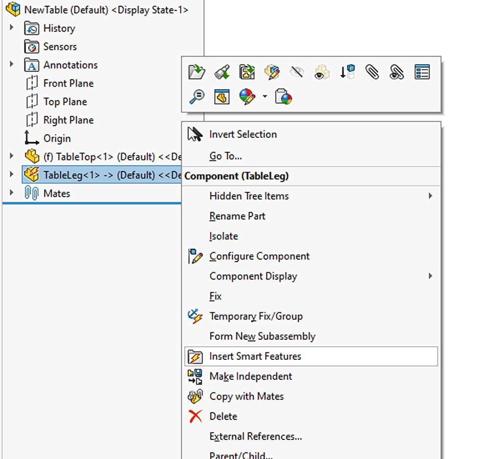
Pictured above is the leg after being mated with the tabletop. The smart features (and components) can then be brought into the assembly by right-clicking on the component (either from the tree or the graphics area) and choosing Insert Smart Features from the dropdown (Fig. 14).
The property manager will appear (Fig. 15), which lists what features and components will be inserted. By default, all accompanying features and components will be brought in, but the checkboxes can be used to selectively toggle some of them on or off. The accompanying features and components are shown here, along with the required references:
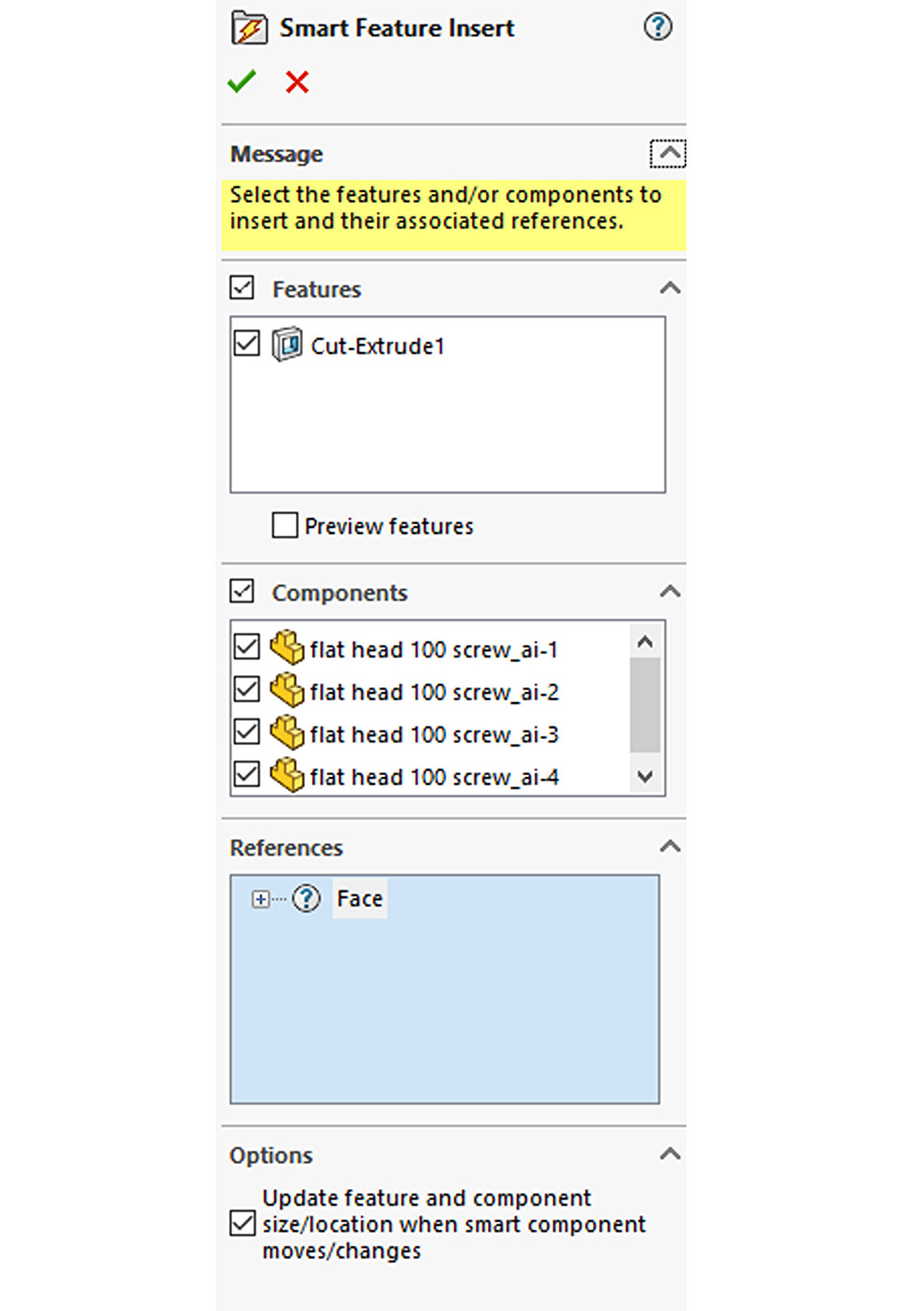
Before continuing, any missing references will also need to be reattached. In this case, a face reference is needed.
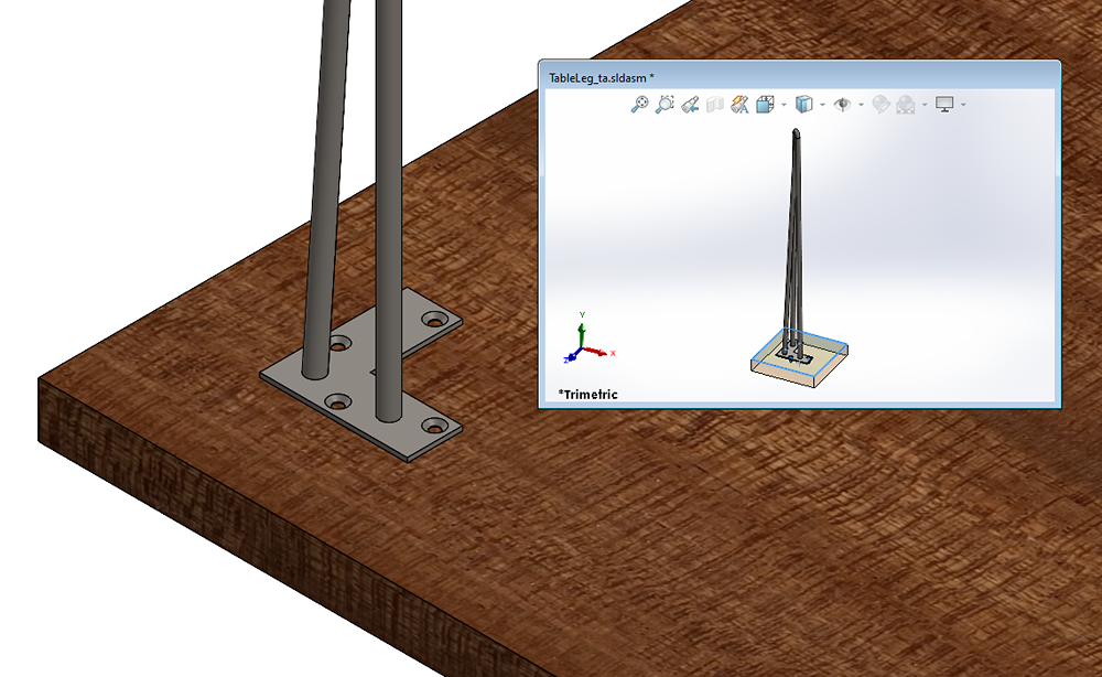
A smaller preview window will appear (Fig. 16) showing the representative assembly that was originally used to define the smart component. The face of the block is highlighted in the small window, which indicates the reference that is currently missing. The corresponding face (the large face of the tabletop the leg is attached to) will be selected in the new assembly. In the case of this table leg only one face reference is needed (which corresponds to the sketch plane for the extruded cut feature). In more complex smart features, more references can be used. The preview window will, in that case, highlight the next reference required after each previous reference is attached.
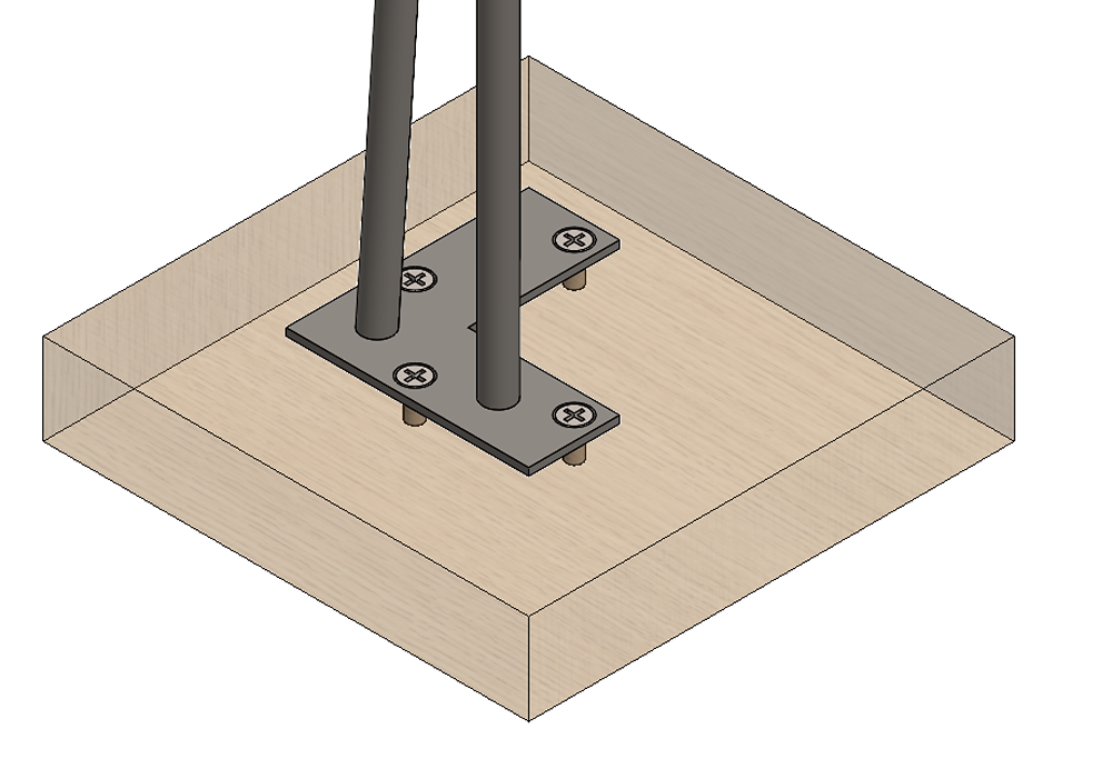
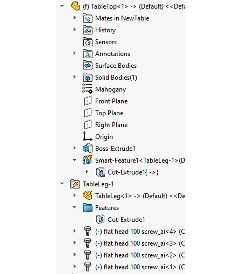
The cut is then added to the tabletop component and the screws are added to the assembly (Fig. 17). Note how the table leg component will change to a folder icon in the tree (Fig. 18), and the fastener components appear in the folder. With just a few clicks to reassign a reference, the holes were cut out for the screws, and four screws were added to the assembly with the proper mates.
Note: While smart fasteners typically can automatically adjust their length, inserting them via a smart component will nullify this ability. If the length of the fasteners is expected to be variable (for instance if the holes did not use a blind end condition, but instead an offset from surface, they would be deeper on thicker tabletops, and shallower on thinner tabletops.) In this case, then the fasteners should be excluded from the smart component and added afterward. In the figure below, transparency is turned on for clarity so you can see the screws are added, as well as an extruded cut in the tabletop.
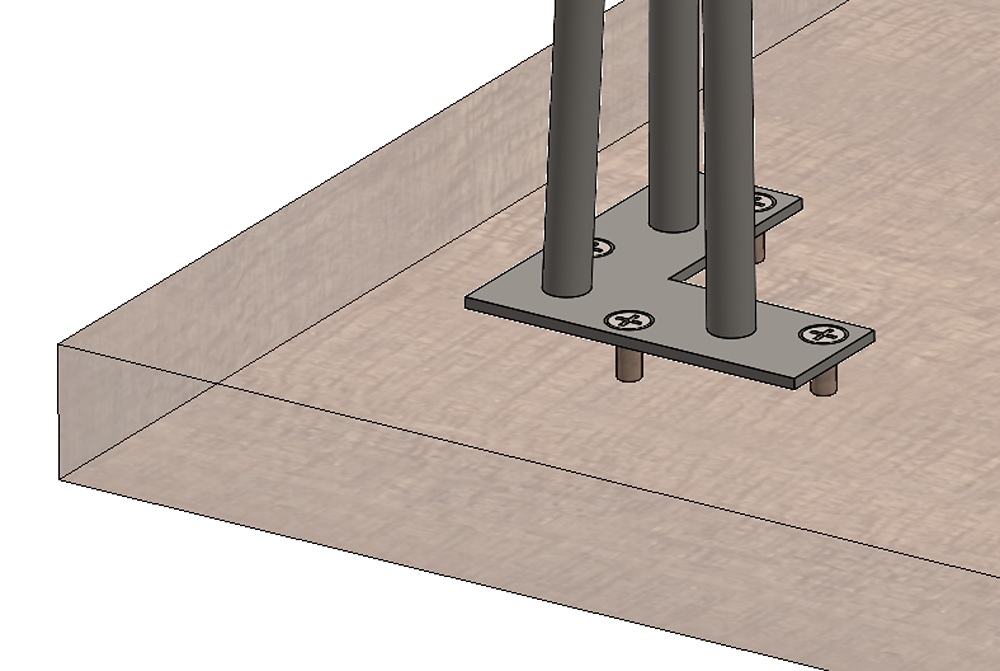
The cut-extrude is now shown under the tabletop component, and the screws are shown in the table leg folder:
How to Edit Smart Components
After a smart component is created, the representative assembly does not affect the component. Any changes must be made from the smart component file, in this case, the table leg part.
To make changes, open the table leg part, and a folder will appear at the top of the tree called Smart Feature.
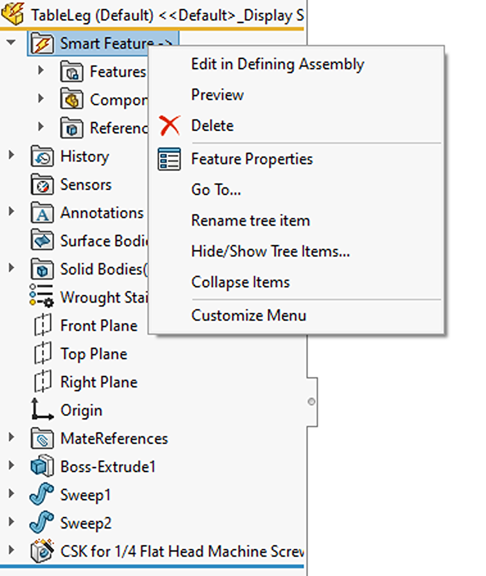
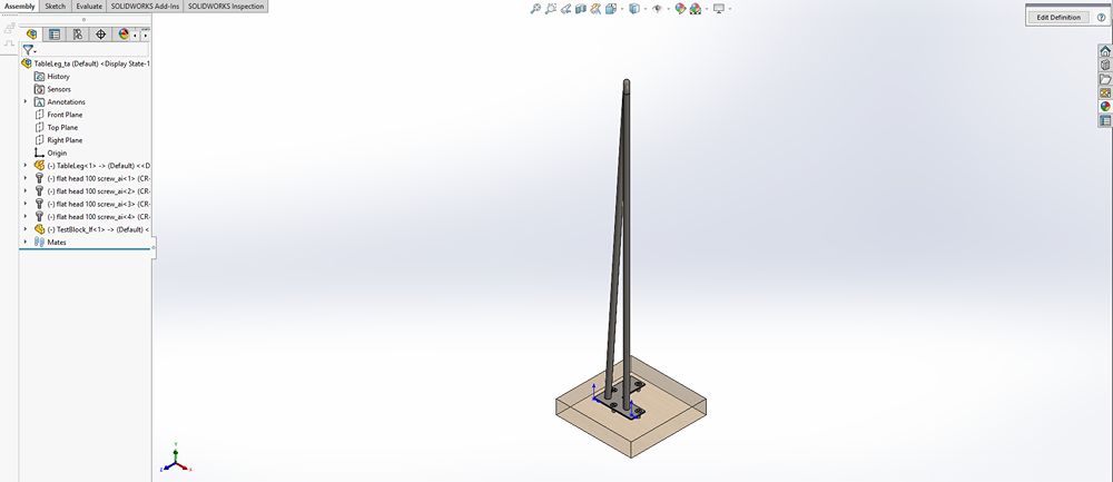
The component can be edited by right-clicking this folder and choosing Edit in Defining Assembly (Fig. 19). An assembly will open (Fig. 20) which allows any changes to be made and saved. To access the smart component property manager where features and components can be added or removed from the smart component, click the Edit Definition button in the upper right corner of the graphics area.
Once all changes have been made, simply close out of the assembly and save to update the smart component file.
Note: While this assembly appears identical to the original representative assembly, it is only a temporary assembly recreated from the smart component data stored inside the table leg part file. The original assembly is no longer linked to the smart component after its creation.
Save Time and Effort with Smart Components in SOLIDWORKS
Creating Smart Components in SOLIDWORKS is a great way to save time and effort for commonly used components with repetitive associated features and components. (In the case of the table leg: cut holes and fasteners). These features and components can then be added to the assembly with just a few clicks instead of manually creating and inserting them every time.
You can learn more about Smart Components and more in one of our many SOLIDWORKS tutorials.
For more information on SOLIDWORKS or if you have any questions, contact us at Hawk Ridge Systems. Thanks for reading!