
Getting Familiar with SOLIDWORKS Hole Wizard
In SOLIDWORKS, hole features can vary in complexity from a simple Extruded Cut to a fully threaded Advanced Hole. For everything in between, however, the Hole Wizard command is an excellent choice, allowing designers to build real intelligence into products and optimize design flexibility and efficiency. In this article, we will be exploring the Hole Wizard command, and learning how to define and apply industry standard holes to a part in the simplest possible manner.
Hole Wizard Command
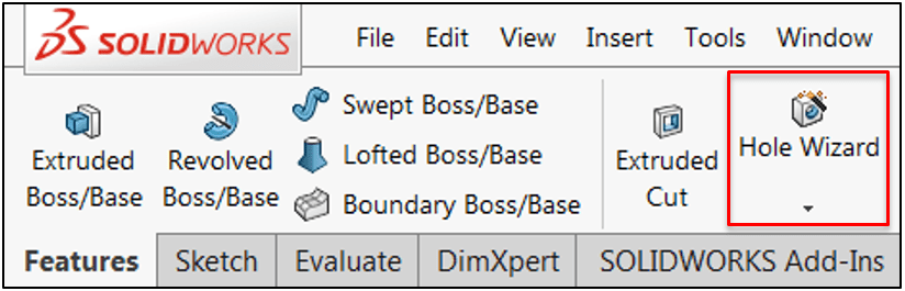
The hole wizard command can be found on the Features tab in the CommandManager:
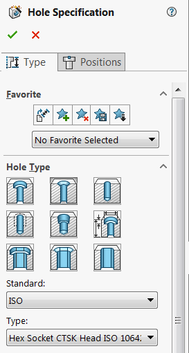
Unlike most traditional sketched features, the Hole Wizard command can be accessed without being in the sketch environment. Once activated, options to define the hole type/specification and position are controlled through the PropertyManager in two unique tabs, as seen below:
Feature Styles
Available feature styles include Counterbore, Countersink, and Tapered Tap, among many others. The “Hole” style is very similar to a standard Extruded Cut hole, but includes standardized sizes and will be recognized by other commands such as Smart Fasteners more effectively. Hovering the cursor over any of the picture symbols will display a tooltip indicating the hole type.
While all hole styles (with the exception of Legacy Hole) include the same standards, the type options will vary according to the hole style selected.
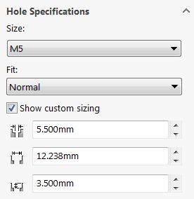
The Hole Specifications group box includes two dropdowns for controlling both size and fit. While the Size category is self-explanatory, the Fit category will allow you to adjust the hole’s dimensions by selecting Close, Normal, or Loose. The values for these fit types are built into the SOLIDWORKS Toolbox Configurator (discussed at the end of this article) and can be adjusted manually if desired. Finally, the Show Custom Sizing checkbox can be activated to override the standard hole dimensions, but we recommend this option be used with discretion, as it may cause fitment issues with applied fasteners.
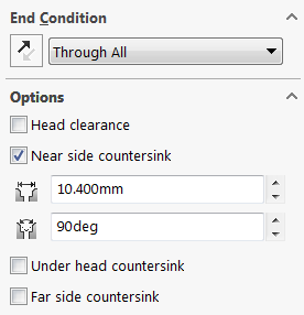
Finally, the End Condition dropdown allows the depth of the hole to be set, and an Options group box provides a number of options for controlling parameters such as head clearance or thread type and will vary according to the hole type selected.
Once all the settings for the hole have been selected, the next step is to position the holes. Click the Positions tab to begin positioning. To position the holes in a planar fashion, simply select a face as a reference. Alternatively, you can click the 3D Sketch button to position holes in 3D (especially useful for adding holes to non-planar surfaces). For more information on using the 3D Sketch option with the Hole Wizard, consider taking a look at this video.
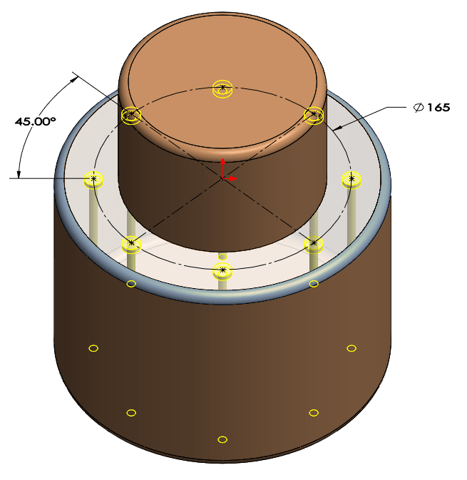
Once the position mode has been selected, sketch mode is automatically activated, along with the Point tool. Each point placed will represent the center of a hole instance, and previews will appear for each instance as it is placed. A combination of construction geometry, sketch relations, and dimensions can be used to fully constrain the hole positions:
It should be noted that each unique hole type/size will require its own Hole Wizard feature, as different specifications cannot be combined into the same feature.
One of the major advantages to using the Hole Wizard over traditional cut methods is the intelligence that is built into it. If you have access to the Toolbox add-in, you’ll also have access to the Smart Fasteners command in assemblies, which leverages existing Hole Wizard features and applies the appropriate fasteners automatically. For more information on Smart Fasteners, consider taking a look at this video on the subject.
Finally, it’s worth mentioning that custom standards for hole size, screw clearance, and thread data can be created for Hole Wizard features using the Toolbox Configurator. Additionally, this dialog can be used to disable specific sizes/standards to avoid accidentally using them in design, and also controls the default fasteners assigned when using Smart Fasteners. For more information on using this dialog, the Help file is particularly useful.
In this blog, we discussed the SOLIDWORKS Hole Wizard feature and showed how to use the associated PropertyManager to define hole type, specification, and position. With a variety of industry standard hole types, from Counterbore to Tapped and everything in between, the Hole Wizard provides a much faster and more intelligent solution to traditional features while enabling productivity tools such as Smart Fasteners. Do you have any additional tips or tricks for using the Hole Wizard more effectively? Let us know in the comments!


