I designed a mounting bracket part for a light bar on my Subaru Outback. This lets me mount a light bar behind the bumper of my car and keep it relatively out of the way.
I used SOLIDWORKS to design the sheet metal part, then an online manufacturing service to cut out my flat pattern and bend it for me.
By designing the part using the built-in SOLIDWORKS sheet metal tools, I can ensure my part is manufacturable based on important parameters like K-Factor and bend radius, which are determined by the manufacturer.
Here’s how I did.
Why I Created This Light Bar
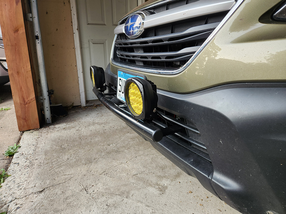
This was my existing solution — a pair of lights outside the Outback’s bumper. While it worked well and provided lots of light close to the ground for dusty or snowy conditions, it stuck out from the car quite a bit.
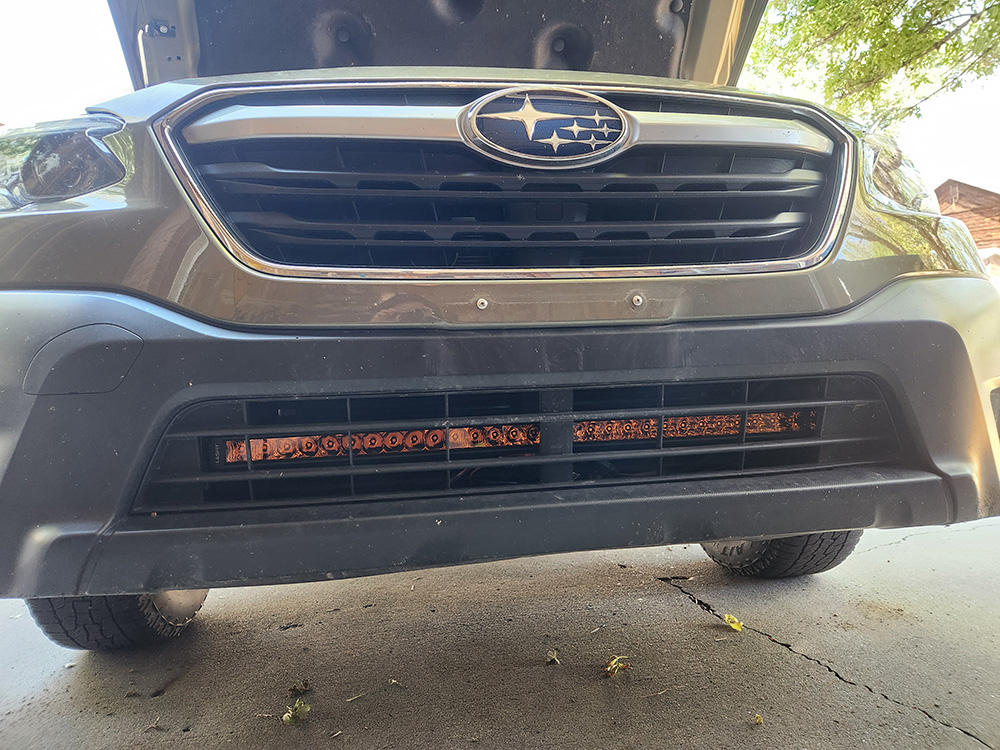
My goal here was to fit a light behind the skin of the bumper. This would eliminate the protrusions of the previous mount, be more subtle, and disrupt the existing aerodynamics of the car less.
With the external mount gone, it also makes it easier to stand closer to the front of the car when working in the engine bay.
While other off-the-shelf solutions like this exist, the ease of SOLIDWORKS means I can design my own bracket that I know will fit perfectly for a fraction of the cost of the off-the-shelf solutions — and with relatively little time.
Designing My Hidden Light Bar
The light bar has two M8 threaded holes for mounting — one on each end. I added a slot to the bracket in SOLIDWORKS using the Hole Wizard feature. This will allow the bar to be shifted up and down so it shines through the gaps in the grille.
Getting the Model Right
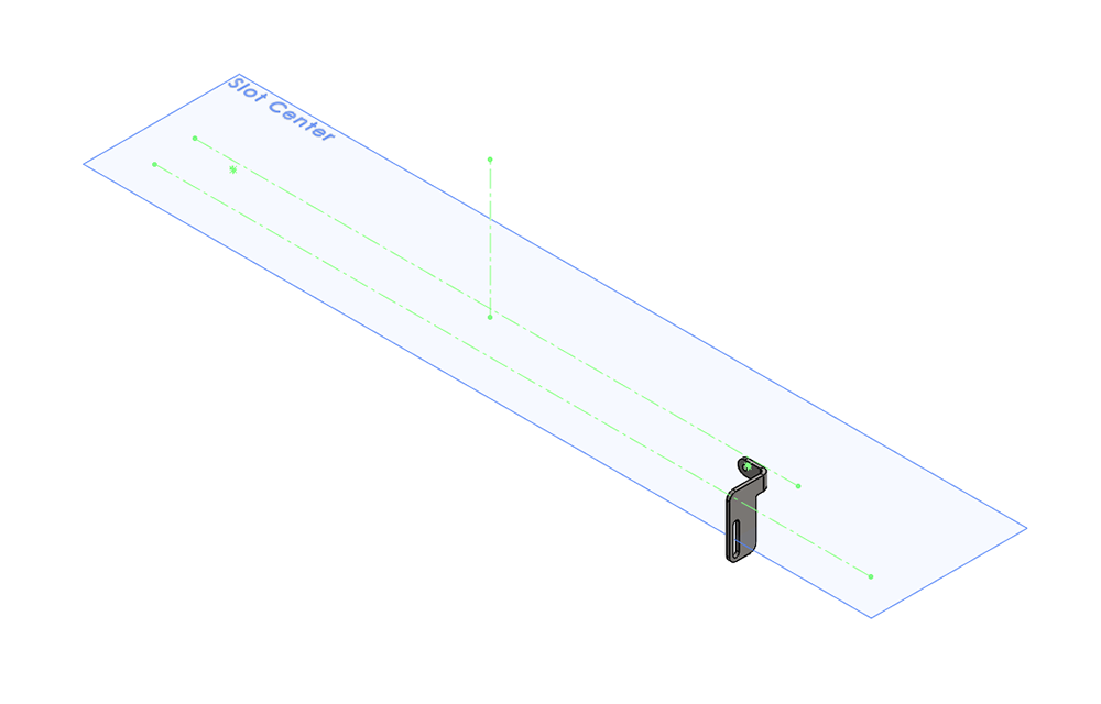
Before beginning my modeling in SOLIDWORKS, I removed the bumper and carefully measured the area where the light would mount to be sure I didn’t interfere with any existing components.
Various construction geometry and reference planes were used as I created the model to represent these nearby obstructions.
Working on the Mounting Brackets
The design of the bracket is relatively simple, requiring only a single bend. The dimensions were determined based on the width of the light and the hole spacing on the car. I carefully made sure to keep the bracket from interfering with any nearby components in the car.
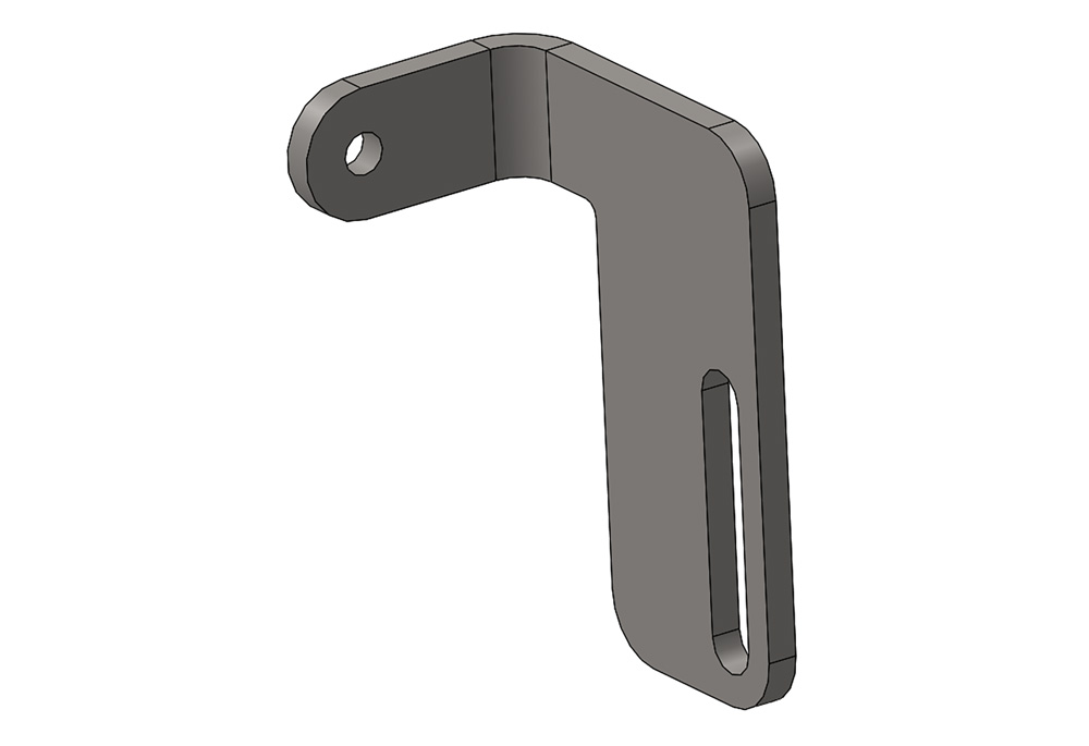
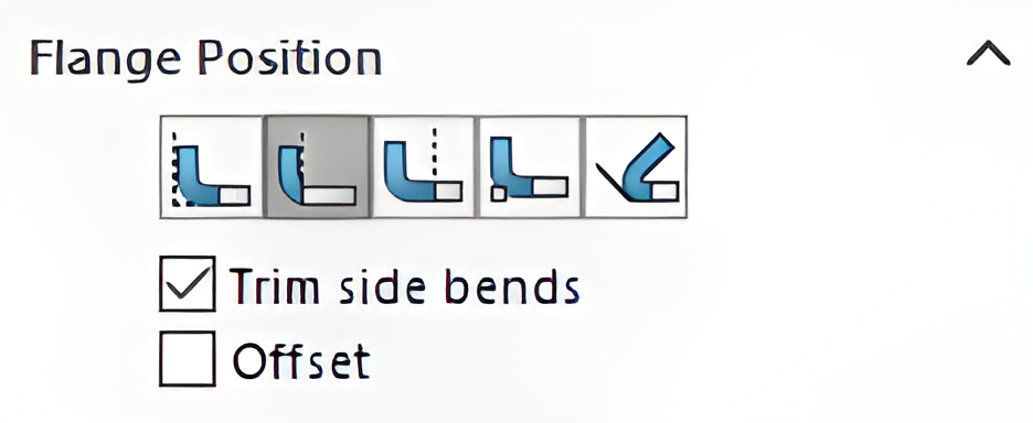
In this part, carefully choosing the flange position was especially important when creating the bend in SOLIDWORKS sheet metal tools. I used the “Material Outside” option to ensure the distance between the inner surfaces of the brackets would be equal to the width of the light bar.
The flange position option determines where the edge flange material is added.
Setting Up My DXF File for Manufacture
Before I could generate my DXF file with the flat pattern, I needed to make sure I had the right sheet metal settings.
I went to my manufacturer’s website and looked up their bend parameters for 3/8” 304 Stainless. I found a K-Factor of 0.35, so I put that in my part’s settings, as well as a bend radius of 0.130in.
SOLIDWORKS will use these parameters to automatically calculate the flat pattern shape from the 3D part. This significantly speeds up the sheet metal design process in SOLIDWORKS.
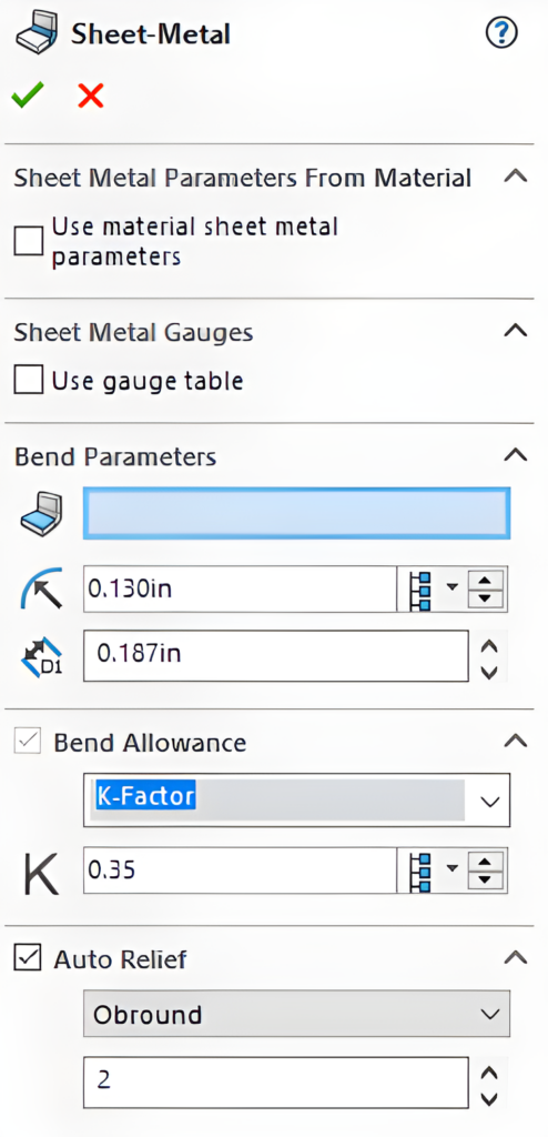
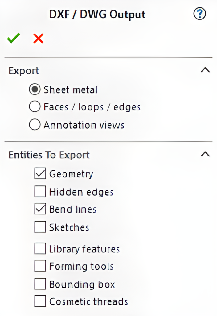
After I entered my sheet metal parameters (thickness, bend radius, K-factor, and relief ratio), I exported the flat pattern to a DXF, making sure to include the bend lines as well. This is as simple as right-clicking on the Flat Pattern feature and choosing “Export to DXF/DWG.”
For this bracket, I’ll need a left- and right-hand version. However, thanks to the relatively simple design, I can reuse the same DXF flat pattern and specify opposite bend directions on each version.
For more complex parts, the Mirror command would work well.
Installing the Brackets and Light
After ordering the parts, it was time to get hands-on. I started by removing the front bumper of the car. This gave me the access I needed to install the brackets and light.
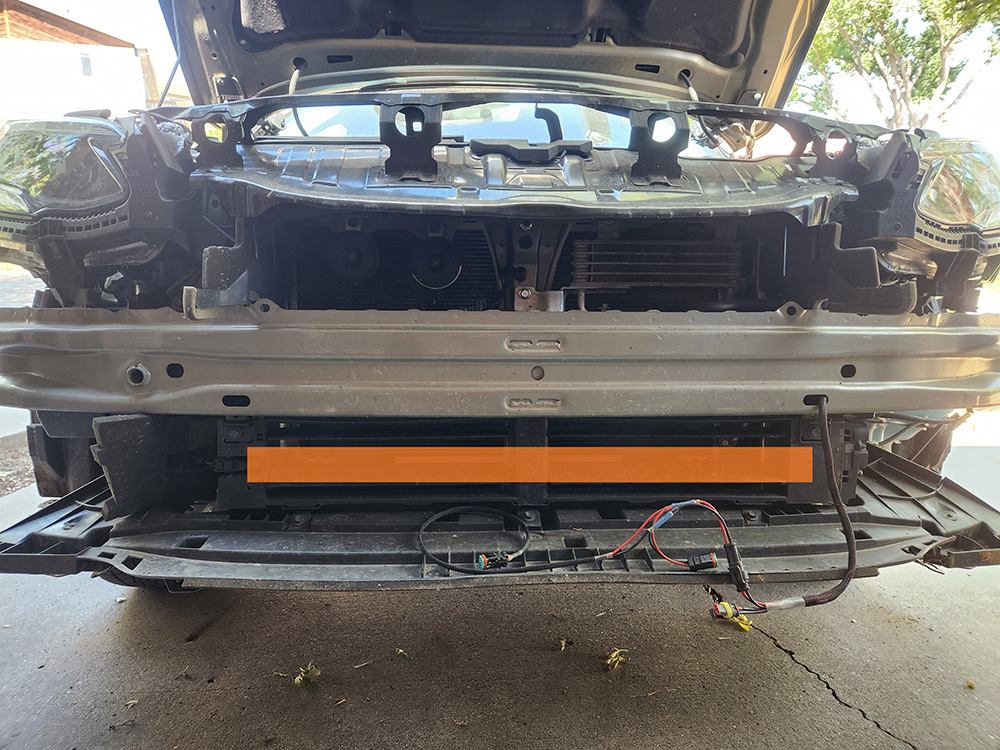
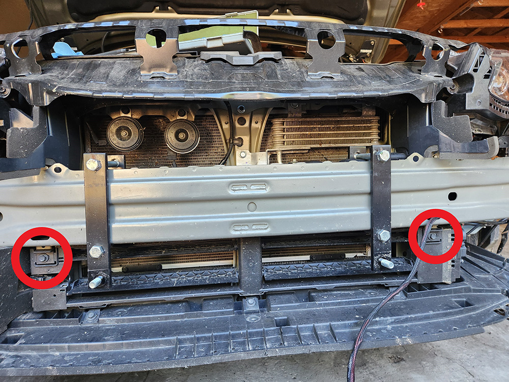
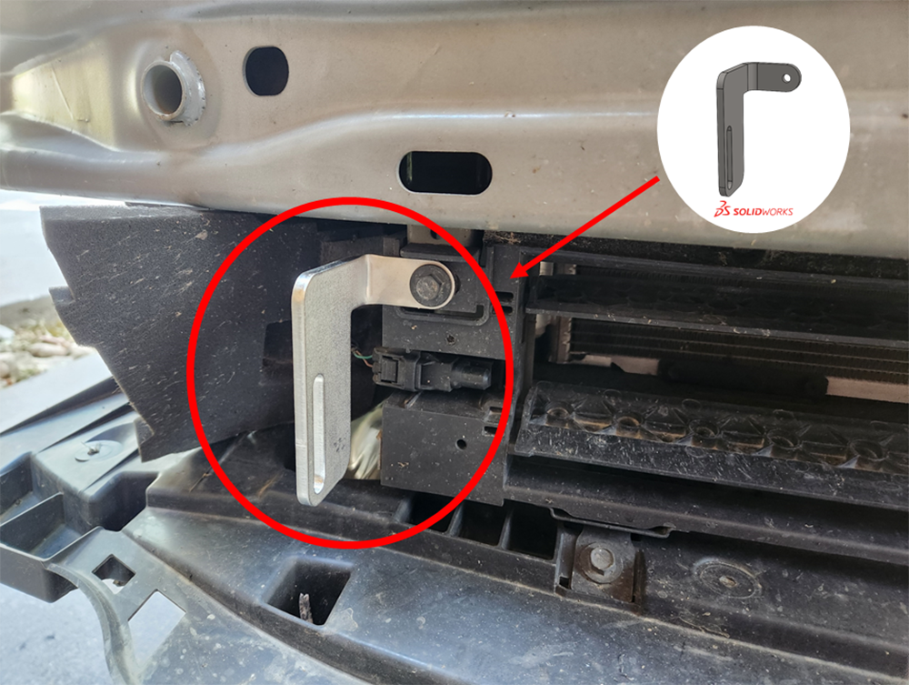
I removed one of the existing screws on the car and sandwiched the bracket underneath it. This is the passenger side bracket after being installed.
The driver-side bracket is installed in the same way. Then, the light bar can be attached to the slots.
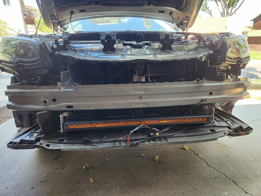
The purpose of the slots on the brackets is more apparent here. The adjustability was necessary to allow the light bar to be shifted vertically to shine directly through the gap in the grille, instead of being obscured by the ribs (the horizontal pieces of plastic) in the grille.
Measure twice, cut once… or just use slots instead of holes.
My Closing Thoughts
My mounting brackets were simple and quick to design. By taking advantage of the built-in SOLIDWORKS sheet metal tools, more time and focus can be spent on the 3D part, while the conversion to a flat pattern is handled in the background by SOLIDWORKS with minimal effort from the user.
While SOLIDWORKS is extraordinarily powerful, it can also be used to make simple custom parts, which can outperform some off-the-shelf solutions without a huge time or money commitment — especially in cases like this for my purposes.
As online small-batch manufacturing services continue to drop in price, the accessibility of these custom solutions combined with the limitless potential of SOLIDWORKS means even garage hobbyists and fabricators can enjoy having their own parts brought to life.
If you have any questions about SOLIDWORKS or the sheet metal tools, reach out to us. We’re happy to help.
