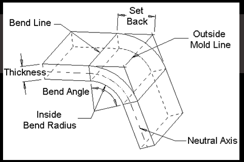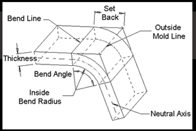
SOLIDWORKS sheet metal tools are relatively straightforward, but may not be clearly understood. In sheet metal, there is a powerful bend constant known as the K-Factor. It ultimately allows you to estimate the amount of stretch without knowing what type of material you are bending. In practical terms, it’s just a generic bend allowance to use when you don’t know the process or machine that is going to be used to bend the sheet. I’d like to review K-Factor and how K-Factor applies to your sheet metal designs.
K-Factor Defined
K-Factor– A constant determined by dividing the thickness of the sheet by the location of the neutral axis, which is the part of sheet metal that does not change length. So if the thickness of the sheet was a distance of T = 1 mm and the location of the neutral axis was a distance of t = 0.5 mm measured from the inside bend, then you would have a K-Factor of t/T = 0.5/1 = 0.5.
SOLIDWORKS and K-Factor
Now let’s take a look at an example of K-Factor. Let’s presume you are creating a sheet metal part in SOLIDWORKS. Let’s start out with a sketch of 10 mm by 10 mm. Once you activate the base flange tool, you have an available list of parameters you need to specify to determine how sheet metal is going to stretch.
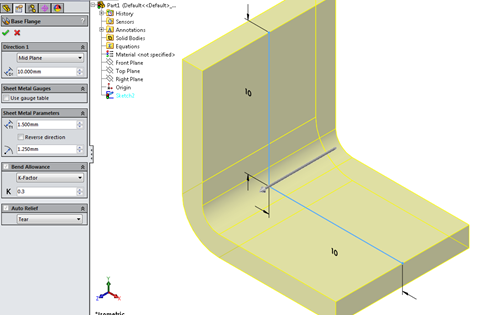
In the picture above, I specified the parameters as follows: Thickness is T = 1.5 mm, Bend Radius is R = 1.25 mm and K-Factor is set to 0.3. Remember, if we needed to know the placement of the neutral axis we would use the formula, K = (t/T) -> t = K × T = 0.3 × 1.5 = 0.45 mm. We can now apply the Bend Allowance Formula using the above information. The Bend Allowance Formula will determine the length of the arc at the neutral axis from one bend line to the other. Let’s take a look at how the Bend Allowance Formula can be applied, using the parameters we specified.
BA = 2 × π × A (R + K×T) ÷360
BA = 2 × 3.14 × 90(1.25+ 0.3×1.5) ÷360
BA = 2.67 mm
WHERE:
BA = Bend Allowance
π = 3.14
A = Bend Angle
R = Bend Radius (inside bend radius)
K = K-Factor
We can see the bend allowance in the flat patterned state evaluates to 2.67 mm. (Note: In the flat patterned state I have the merge solids option selected off. This allows me to take the measurement of the length of the bend.)
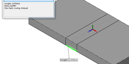
You can also determine the size you would need to cut your sheet. L1 and L2 have sketched dimensions specified. You can verify this by flattening out the sheet and measuring the length from the edge to the center.
LF = L1 + L2 – R ×2 +BA
LF = 10 + 10 – 1.25 × 2 + 2.67
LF = 20.17 mm
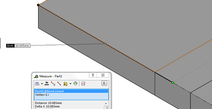
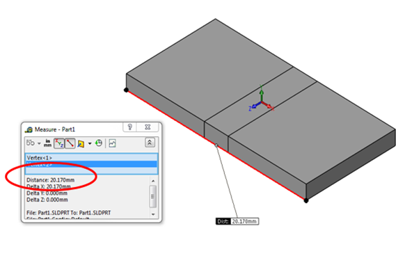
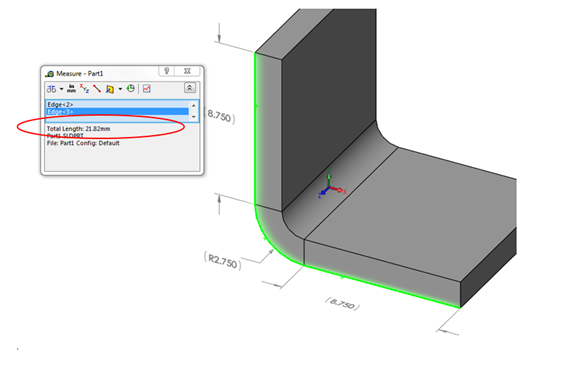
So you would need a size cut to 20.17 mm. If necessary, you can determine the amount of stretch. The total length when bent is Total Length = 8.75 + (π×2.75÷2) +8.75 = 21.82 mm resulting in the stretch = 21.82 – 20.17 = 1.65 mm.
Practically, if you are wondering how to determine K-Factor for your industry, it is simply determined by material type. In other words, calculations have already been done for you. In SOLIDWORKS there is a list of sample tables for materials such as steel and aluminum. These sample tables yield acceptable results, but should always be verified by your company first. A sample steel gauge table looks like below. Tables can be found at Program FilesSolidWorks CorpSolidWorkslangenglishSheet Metal Gauge Tables folder.
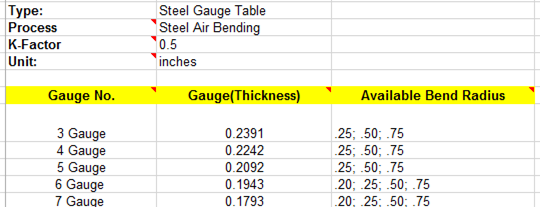
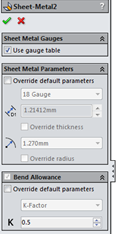
Notice the above K-Factor has already been set for you. So when you set your parameters, you can be confident that a K-Factor of 0.5 will lend your acceptable results. Also, notice below K-Factor is pre-set in the property manager, as well as thickness (gauge) and bend radius.
Final Thoughts
I hope you enjoyed this tutorial on K-factor. Please check back on this page for more updates on SOLIDWORKS, other products, and our ever growing list of products we specialize in. If you have any questions about SOLIDWORKS or Sheet Metal design, please CONTACT US.
