When exploring the world of industrial 3D printers, it can be challenging to understand what benefits can be gleaned from systems and resources involved in operating and maintaining sophisticated equipment, especially in the early planning phases.
With the large variety of printing systems and technologies out on the market today, where do you start?
In today’s blog post, we are going to provide insight into what you need to know when you get started with industrial 3D printers.
Top 3 Common 3D Printing Technologies
When starting your 3D printing (or additive manufacturing) journey, it is important to understand the different print technologies and their high-level benefits.
Printing systems can be divided into three categories based on the raw material configuration. The three categories are:
- Filament-based printing systems like Markforged fused filament fabrication (FFF)
- Resin-based printing systems like Formlabs stereolithography (SLA)
- Powder-based printing systems like Formlabs selective laser sintering (SLS)
Each print technology will have unique advantages and applications, although there certainly are use cases that will be successful in all three technology categories.
Let’s explore each one closely using a real-life example 3D printer that we offer here at Hawk Ridge Systems.
1. Working with Filament 3D Printers Like Markforged FFF
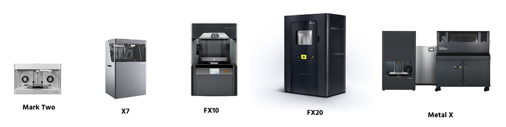
Good examples of filament-based printers are the Markforged industrial 3D printer lineup.
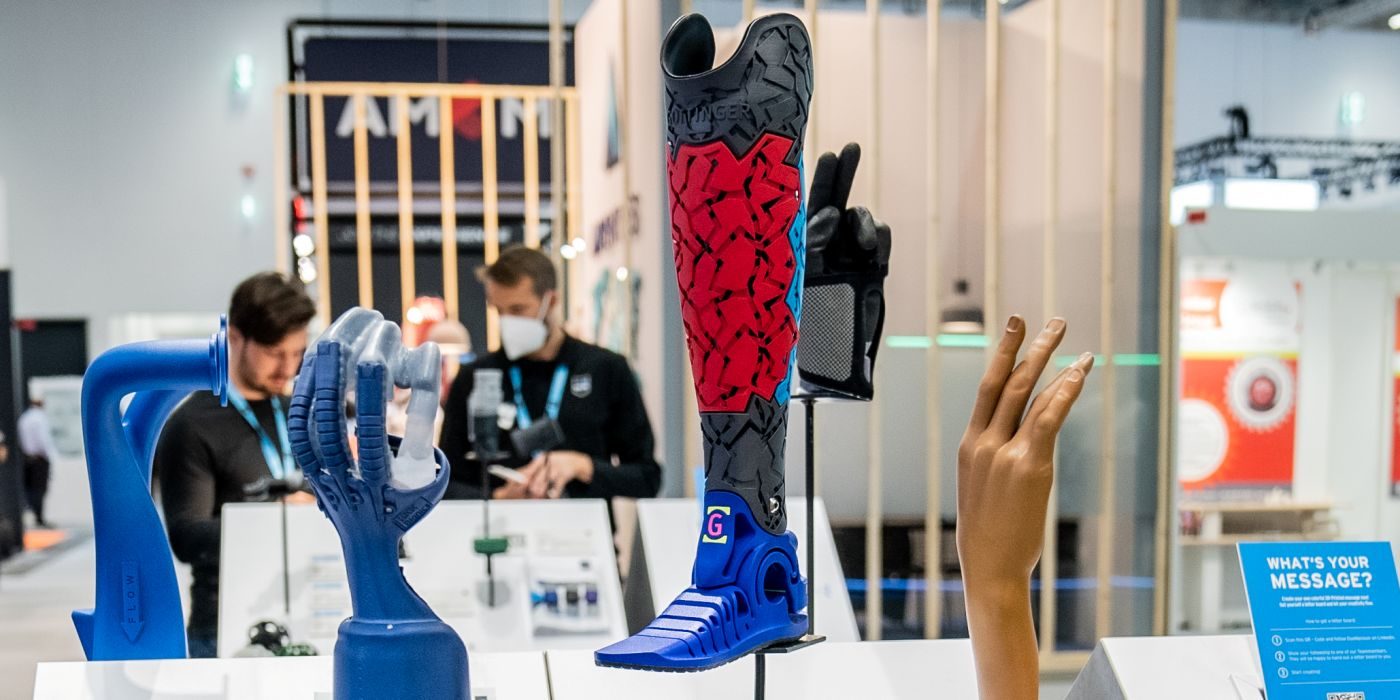
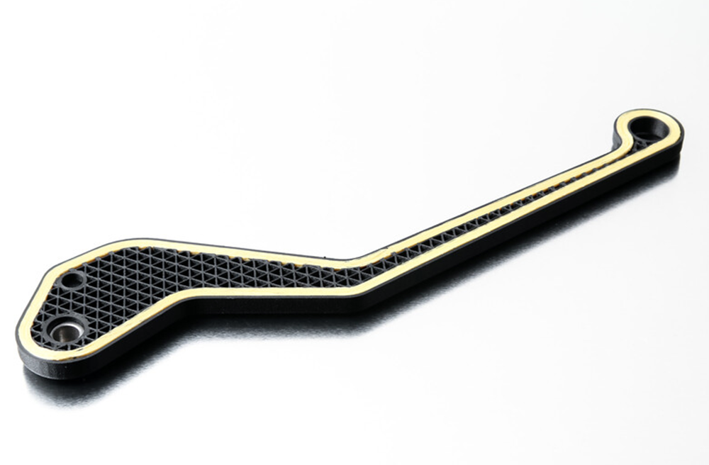
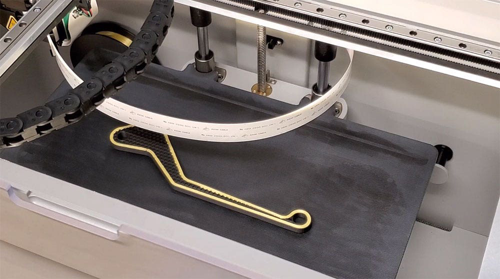
Markforged is known for tough-as-nails industrial fused filament fabrication (FFF) 3D printers that are made for the factory floor. In addition to printing with raw filaments, Markforged printers have the ability to embed plastic parts with continuous fibers in a process called continuous fiber reinforcement (CFR).
Parts that are printed with CFR are incredibly strong and lightweight. These parts can often replace aluminum machine components due to their extreme strength and durability.
In fact, this is where Markforged FFF advantages over other print technologies on the market. Markforged printers revolve around incredible part strength, ease of use and installation, software tools (such as simulation and inspection) and aerospace grade materials (such as Ultem 9085 filament and Vega (PEKK)).
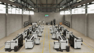
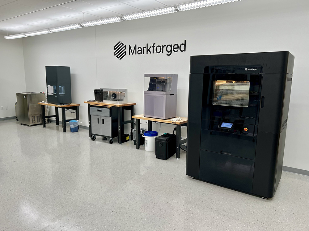
Markforged has several industrial 3D printers to choose from, including the noteworthy Metal X FFF-style 3D printer that’s perfect for industrial applications. The company also offers a range of composite printers for businesses.
Common Filament Applications
Common applications for filament 3D printers include jigs, fixtures, assembly aids, soft jaws and structural components.
Unlike most filament printer companies, Markforged also has materials with flame retardant properties that meet NCAMP certifications geared toward the aerospace and defense industries, along with machines that can operate completely offline for high-security environments.
Markforged also has made a name for itself in robotics competitions such as battle bots due to CFR parts being so much stronger than other printed parts on the market.
Common printing needs such as prototyping, enclosures and cosmetic pieces are all possible with the Markforged system, making these systems highly versatile.
Markforged printers are an excellent place to start when diving into the world of additive manufacturing.
Designing Parts for Markforged FFF & CFR
Designing parts for a Markforged system primarily involves planning for support structure removal and part strength.
Support structures can often be eliminated by adding chamfers and angled surfaces to your CAD designs to eliminate overhangs. These small CAD changes can save time and improve the surface finish of the part.
Designing for part strength involves maximizing X-Y cross section to provide more space for continuous fibers. FFF parts are weaker in the Z-direction, so it is good to prioritize critical areas of the geometry to X-Y directions for maximum strength.
Markforged simulation is also a valuable tool to quickly dial in a design for FFF printing.
Installation & Facilities Considerations
Both installation and facility factors can affect your workflow and operations. With Markforged products, there are a few factors to consider when it comes to your facility and installations.
Power Requirements
The nice thing about Markforged printer installation is that every Markforged composite printer, aside from the large format FX20 printer, will plug into a standard wall outlet, and there are no requirements for additional auxiliary equipment.
When we talk about industrial printers, they typically require more power. The FX20 industrial 3D printer requires 3-phase 240V power that your facility will need to accommodate to run the printing system, compared to the Metal X printer, an office-friendly printer, that plugs into a 110V outlet.
Installation involves powering the machine, loading materials and leveling the print bed — that is it!
This ease of installation makes Markforged printers very easy to plan for from a facility perspective and easy to move on the fly.
Network Connection
Each Markforged printer will require a network connection either via Wi-Fi or hardwired connection, unless the system is utilizing Offline Eiger software.
Space Requirements
The Markforged Metal X printer has a few additional considerations such as a facility exhaust for the wash station and sinter oven. This facility’s exhaust requirement can be eliminated through the use of a BOFA extraction unit.
The Metal X sinter oven also requires the use of argon & an argon/hydrogen mix gas, and the wash station requires the use of an Opteon solvent.
Other Factors to Consider
Other factors are odors and noise. Markforged printers do not put off any odors, and they are quiet, which is perfect for an office environment or the factory floor.
In fact, all the Markforged Metal X equipment is very quiet in operation with very minimal PPE requirements, especially compared to other metal print technologies.
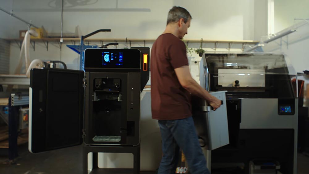
Operating Markforged Printers
Now, let’s explore more about how to operate your Markforged 3D printers. We’ll dive deeper into the software, the printing process and the post-printing process.
Eiger Software – Preparing and Submitting a Print
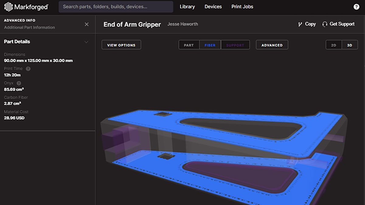
The operation of a Markforged printer first involves using the Eiger software, which is one of the best 3D printing build management solutions on the market.
Eiger has both cloud-based and offline versions with the cloud-based version being free to use. The software is built on a file folder structure with role-based access control capabilities (RBAC) and enterprise software APIs for complete control and integration capabilities for scalability.
The cloud-based version of Eiger is the most collaborative additive software solution we have seen on the market, allowing numerous users in an organization to work together and print parts from all over the world.
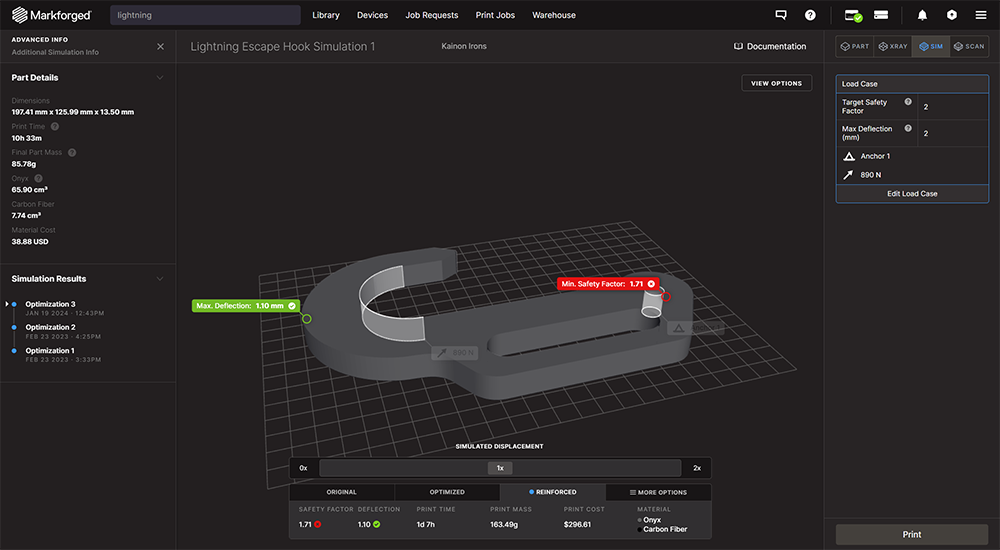
Eiger also has a simulation add-on that allows users to run strength analysis on printed parts by applying loads, anchors, deflection targets and factor of safety targets. Simulation will automatically optimize the internal slice parameters to meet the design load criteria, which takes the guesswork out of selecting print parameters.
Sending prints to the machine can be done remotely via the cloud, securely on the local network, or directly via USB connection.
Printing Process
Before submitting a print, users are instructed to apply a thin layer of adhesive on the print bed to ensure that melted filament adheres to the print surface. If the bed is clear on the machine, prints can immediately start once submitted from the Eiger software.
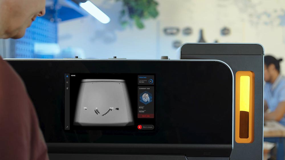
Once the job has been accepted by the printer, the machine will produce the desired part without the need for human supervision. The system will communicate current print progress through the Eiger software, and most print models have a camera to remotely monitor prints.
Markforged printers typically have two nozzles: one dedicated to plastic and a second nozzle dedicated to continuous fiber. The machine will layout filaments, fibers and support structures until the part or parts are complete.
Post-Print – Support Structure Removal
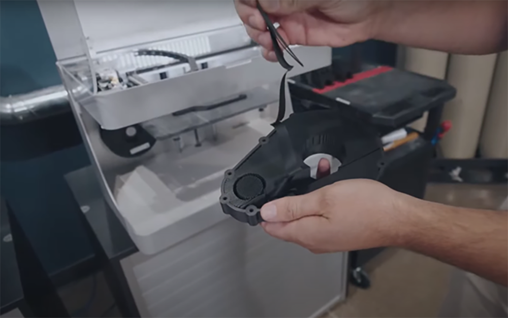
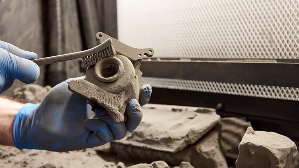
After the print is complete, the user can remove the print bed or sheet and then scrape the parts off the print surface. Afterwards any support structures can be removed by hand or by using needle nose pliers.
For most printed materials, the support structures will match the plastic being printed. Support structures are automatically generated in the Eiger software in an accordion-like shape, which is quick to remove.
One advantage of the Markforged support removal process is that no additional equipment, chemicals, or tools are needed to finish off printed parts. Markforged printers are the cleanest systems, especially in the post-print process out of all the additive technologies that we offer.
Maintaining Markforged Printers
Maintenance on a Markforged printer will typically involve bed leveling every two weeks and replacement of consumables on a set maintenance schedule that is continuously monitored by the machine viewable in the Eiger software.
These systems are very easy to maintain with the primary maintenance items being nozzle changes, boden tube changes and belt tensioning.
Markforged has a comprehensive set of support packages called the Digital Forge, designed to minimize downtime and maximize productivity.
Material swapping on a Markforged printer will typically take about 10 minutes and involves removing an old spool from the included dry-box, and then loading a new spool into the dry box, followed by feeding the filament through the boden tubes until it reaches the extruder motor, which will grab the filament and purge a small amount before completion.
Available Training & Support
Markforged has developed Markforged University, which is an online platform with excellent self-paced courses and modules to bring users up to speed quickly with printing systems.
You have access to the platform with the typical support package called Digital Forge. Larger printing systems such as the FX20 and Metal X have both onsite and online training options that are included with the purchase of your Markforged equipment.
Hawk Ridge Systems also offers additional Markforged training with our expert application engineers. We have dedicated support teams to assist customers like you with break fixes, part replacement (parts are covered in support plans) and troubleshooting.
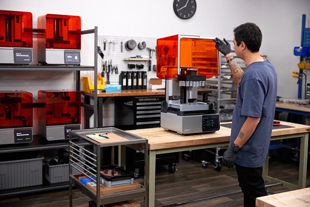
2. Working with Resin 3D Printers Like Formlabs SLA Systems
Formlabs is an industry giant in additive manufacturing, built upon a foundation of worldclass SLA 3D printing systems.
Stereolithography (SLA) print systems offer three key advantages over other 3D printing technologies on the market:
- Smooth surface finishes
- A wide range of materials including transparent materials
- High-resolution print capabilities for extremely fine features
Formlabs has over 30 available materials, ranging from tough engineering-grade materials to elastomers, ceramics, medical and draft materials.
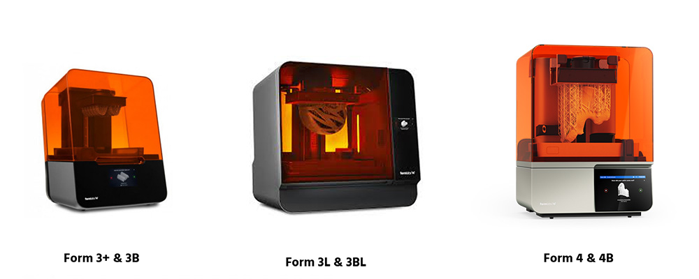
Formlabs SLA printer models consist of the Form 3+/3B+, the Form 3L/3BL and the new Form 4/4B.
Common Resin Applications

Applications for Formlabs SLA printers are numerous due to the wide range of materials and mechanical properties that can be achieved with these systems. They include rapid prototyping, tooling, manufacturing aids, end-use parts and high-definition models and props, just to name a few.
Medical applications are common for Formlabs SLA print technology due to the high variety of biocompatibility certifications for several resin materials.
When one machine can produce soft silicone parts and incredibly rigid technical ceramics and everything in between, you know that the system is going to be suitable for the most demanding use cases.
Designing Parts for Formlabs SLA
Formlabs SLA print technology can handle extremely fine features which opens up a lot of design opportunities. Primary design rules for SLA revolve around managing supports and preventing resin encapsulation in hollow chambers within the part through small drain holes.
Installation & Facilities Considerations
Once the printer has arrived, setup includes leveling the printer, setting up a network connection (update the printer if necessary) and inserting consumables (resin cartridge, resin tanks and build platform), and then you are ready to print!
Power Requirements
Installation of Formlabs SLA printing systems is plug and play with the equipment only requiring standard 110V power, along with a dedicated network connection.
Space Requirements
SLA systems require a wash station that typically uses an IPA solvent as well as a curing oven for a three-step print process. Both the wash station and the cure oven also utilize 110V power.
To prevent any sensitivity to smells, it is best practice to place the wash station in a well-ventilated space or near an open window when in use.
Operating Formlabs SLA 3D Printers
Let’s look closer at how to operate the Formlabs SLA 3D printers by talking about the software you need, the printing process and the process after you finish printing.
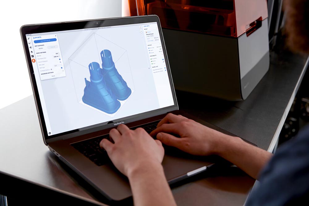
Preform & Dashboard Software – Preparing, Submitting and Monitoring a Print
Preform is a free software solution to prepare and submit prints to all the Formlabs printing systems. For the SLA systems, Preform has tools for automatic orientations and support structure generation, along with options for customization.
Materials and layer height options are built into the software and print specifications including materials used and print time for builds.
Dashboard is an online platform designed to monitor prints and printer utilization and track consumables with options for advanced statistics and data gathering on the equipment.
Printing Process
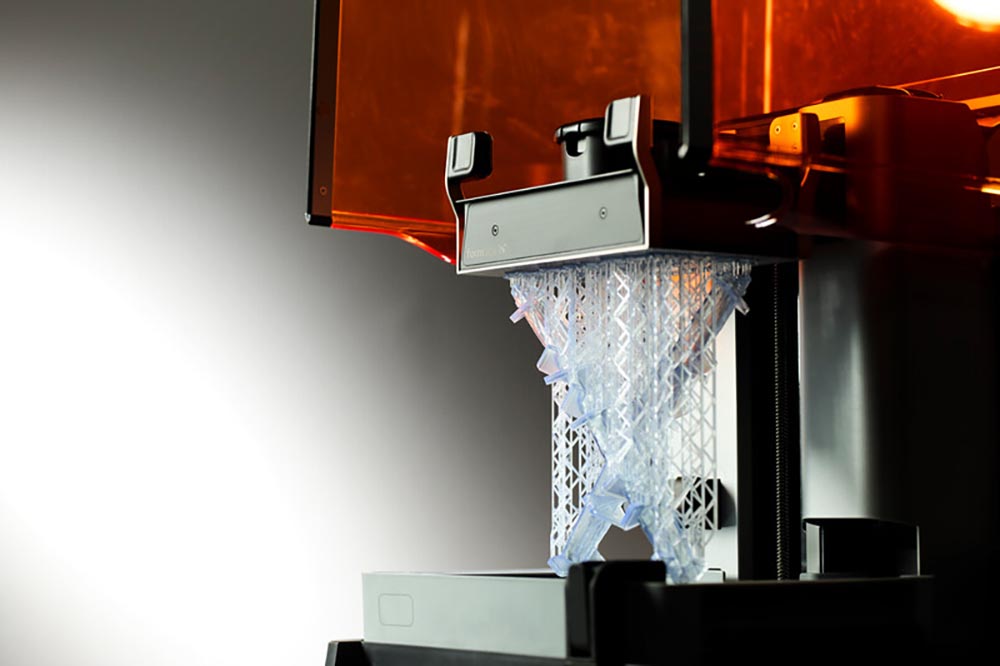
Formlabs SLA printers use light-reactive thermoset materials or resins, which fuse together when exposed to a UV laser that combines layers together until a print is complete. The printer produces parts upside down on a build plate as the machine prints and dips the part in and out of the resin. The machine can run unattended.
Post-Print – Washing, Curing, and Support Structure Removal
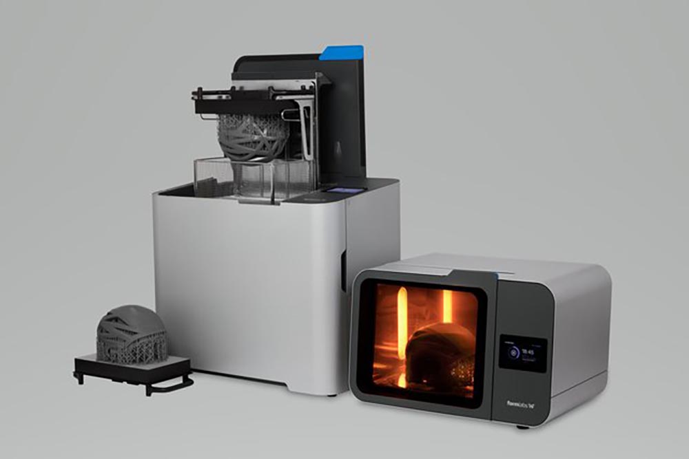
After a print is completed, parts require rinsing in isopropyl alcohol (IPA) to remove any uncured resin from the surfaces of the parts. After parts dry, many require post-curing, which helps printed parts achieve their maximum strength and mechanical performance. The last step is to remove supports from the parts and then sand any support interfaces for a smooth finish.
Maintaining Formlabs SLA Printers
Daily maintenance tasks involve inspecting the build platform for either liquid or cured resin. If necessary, use IPA, paper towels and a paint scraper to remove any resin before starting a build.
Monthly maintenance involves cleaning the optical window on the laser processing unit. Otherwise, additional maintenance items are needed, such as replacing resin cartridges. Explore this full list of Form 3 maintenance schedules.
Available Training & Support
Formlabs has a nice selection of quick start guides, learning pathways specific to various industries, trainings, seminars and custom one-on-one training sessions all designed to ensure users can hit the ground running when onboarding with a system.
Formlabs has a robust support network, along with service plan options, and a database of dedicated support documentation. In the Formlabs pro support plan, there is email and chat support, phone support, live customized training and hot swap part replacement.
3. Working with Powder-Based 3D Printers Like Formlabs SLS Systems
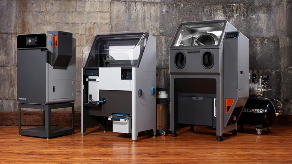
Formlabs entered the world of SLS 3D printing with the release of the Fuse 1 back in 2021 and quickly took a major part of the selective laser sintering (SLS) market share.
Over half of SLS systems sold globally are Formlabs Fuse SLS 3D printers. This incredible industry adoption is due to the high-quality user-friendly workflow, material variety and printed-part quality at a much lower price point than most other SLS systems on the market.
SLS is a powder bed fusion print technology that is much faster than other print technologies producing highly robust pieces that are ready for end-use applications.
One distinct advantage of SLS print technology is that designers do not need to account for support structures, which frees up what is possible from a design perspective.
The latest and greatest SLS system from Formlabs is called the Fuse+ 30W.
Common Powder Bed Fusion Print Applications
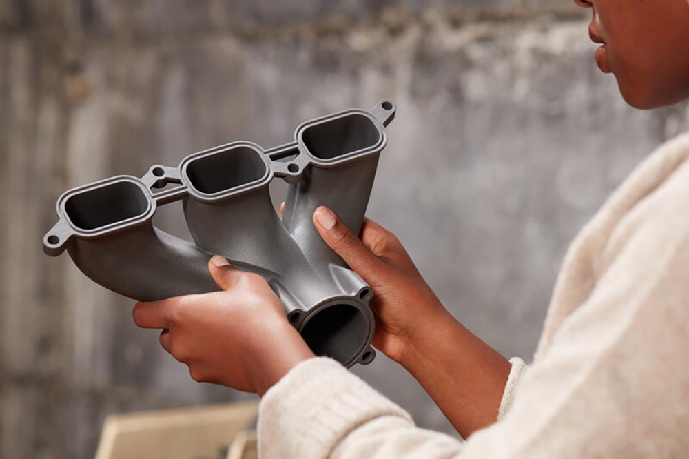
Powder bed fusion parts tend to feel more robust than other print technologies, especially since the parts do not require support structures during printing. With Formlabs SLS, there are tons of potential applications. Your standard prototyping and manufacturing aids will certainly be your go-to application options.
However, SLS is better suited for end-use part production due to faster print speeds and the ability to automate post-processing steps with a print process that is incredibly flexible from a design perspective. Parts with a lot of curvature and internal cavities are no problem for SLS print technology. Printable textures also look amazing on SLS printed parts.
Designing Parts for Formlabs SLS
Part design for SLS is very simple compared to other print technologies on the market. Since SLS is a powder bed print process, there are no support structures required.
The powder itself supports models as they are being printed. The main consideration with design is to ensure that the geometry does not trap powder.
Otherwise, internal features, lattices, curved surfaces and textures all do amazingly well with the Fuse SLS print process.
Installation & Facilities Considerations
The fuse system is plug and play with the printer and sift, each requiring 110V power on a dedicated NEMA 5-20R socket. Systems are commonly installed by the end-user, although there are options for installation services.
Post-Processing Considerations
Since the fuse system is a powder bed technology, there are a few unique considerations to post-process your parts and to keep a clean environment.
The fuse system typically comes with a sift system designed to streamline unpacking of builds and recycling of powder. This system significantly reduces the mess and labor associated with utilizing the fuse platform.
Proper ventilation is a must-have for a fuse system to ensure fresh air exchange and proper operating temperature for the system. An auxiliary vacuum (Class II, Division 2) is also required for general dust collection and cleanup of the system.
The last step in post-processing powder bed parts is bead blasting. This can be done through a manual bead blast cabinet or the automated Fuse Blast system. The bead blast cabinet requires a compressed air supply, which should also be considered in the desired workspace. Room temperature and humidity are also specified at 64-84ºF (17.8-28.9ºC) and 50% or less relative humidity, respectively.
Operating Formlabs SLS 3D Printers
Now we’ll explore what you need to operate the Formlabs SLS 3D printers. We’ll discuss the type of software, the printing process and the post-printing process.
Preform & Dashboard Software – Preparing, Submitting, and Monitoring a Print
The free Preform software is an excellent tool for prepping builds, nesting parts and sending prints to the machine. The automated nesting function is excellent as it quickly fits multiple parts of different shapes and sizes in the most optimum orientations for packing efficiency.
Dashboard is a separate software solution that allows users to view or monitor jobs, plan print times and understand in-depth analytics about usage rates for materials and printers.
Printing Process
The Fuse 1+ 30W printer uses SLS print technology, which involves sintering specific regions of powdered material layer by layer.
To start the print process, a user will need to load a build chamber into the printer and then load powder into the machine hopper before starting the job. The printer then will sinter all the part geometry for a build within the build chamber.
Once all the parts are sintered, the system will pause for a cooling period. Builds can cool outside the printer once the chamber temperature has fallen below 212ºF (100ºC).
Post-Print
After a print and cooling are completed, it is time to unpack the job using the Fuse Sift station. The sift has a dedicated docking port for the fuse build chamber, and the system will allow users to lift the printed build upwards for easy part unpacking and powder recovery.
Once the parts have been unpacked, the last step is to bead blast the parts to remove any residual powder. The Fuse Blast is an automated depowdering system that integrates perfectly with the fuse ecosystem for quick processing of parts ready for end-use applications.
Maintaining Formlabs SLS Printers
The Fuse system’s primary maintenance items involve cleaning sensor lenses and windows and vacuuming up residual powder in the printer. Explore this complete list of maintenance items for the Fuse 1 generation printers.
Available Training & Support
Upon installation of the system, there are both onsite and online training options available to you. Formlabs has dedicated training webinars and documentation available to ensure users hit the ground running with a new printing system. The Fuse support plan includes email and direct phone support and onsite repair in coordination with the Hawk Ridge Systems support team.
The Final Note
Now you should have a good idea of what it takes to get started with industrial 3D printers from Markforged to Formlabs. It’s an exciting time to get into 3D printing and your additive manufacturing journey.
For pricing and more info about industrial 3D print systems, contact us at Hawk Ridge Systems today!