Even though FEA tools are a huge part of the product development cycle, they are very rarely used in conjunction with 3D printed parts. Variables such as layer heights, sparse infill geometries, and multiple-material builds make it extremely difficult or time-consuming to obtain accurate results using traditional simulation software. This means that users of 3D printed parts usually print their part, test it manually, then repeat the process if needed. Even though additive manufacturing is often associated with reducing turnaround, all of this results in valuable time being spent testing rather than implementing.
This all changes with Markforged Simulation, a built-in FEA tool that can validate any Onyx or Carbon Fiber reinforced Onyx part uploaded to the Eiger slicing software.
In this article we’ll cover five quick steps to validate your parts with Markforged Simulation:
- Access Simulation in Eiger: Upload your part in Eiger and select the Simulation button
- Set Up Load Case: Defining Anchor and Load on part surfaces
- Validate Print Settings: Save the Load Case and select Validate and Review results
- Optimize Print Settings: Check out alternative configurations and select your preferred option
- Prepare for Printing: Apply settings with preferred setup and click apply
Markforged Simulation Video Tutorial
Rather watch than read to see the latest updates? See Jesse Haworth and Kainon Irons give you a walk-through tutorial on how to validate your parts with Markforged Simulation software:
Set Up a 3D Printing Simulation
Because Markforged Simulation is meant to validate 3D printed parts, it is directly accessible within Eiger once a file is sliced and ready to print. Since Eiger is a cloud-based slicer, there is no need for any local software updates or dedicated simulation hardware. Once a part is sliced, Eiger users will be able to configure it for a study by selecting the new Simulation button while viewing a part. This will take users to the Simulation Configuration tool.
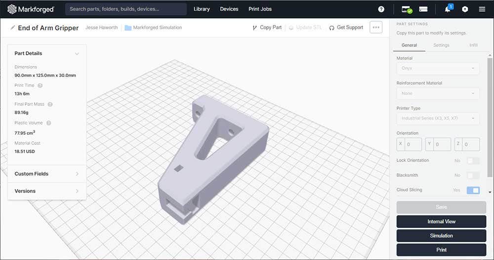
Once a part is uploaded to Eiger and ready to print, users will now be able to access the new Simulation button located in the lower right-hand corner of any Onyx or Onyx and Carbon Fiber part.
Inside the Simulation Configuration area, users will be able to set up the Load Case for their part. At a minimum, a load case will require at least one Anchor and one Load surface. Within Simulation, an Anchor defines where a part will be constrained from moving while a Load will define where a part will be subject to external forces. Both can be easily set up by selecting a part surface and defining it as either an anchored or load-bearing area.
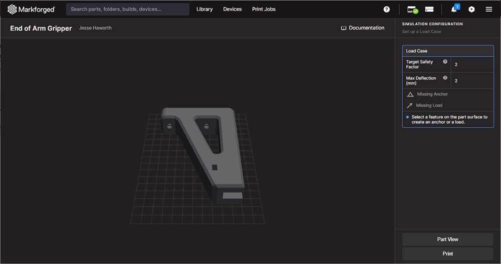
Users can easily set up and view their Load Case once inside the Simulation Configuration tool.
Both Anchors and Loads can be set up by selecting a part feature or surface. Common locations for Anchors are bolt or screw holes.
When setting up a Feature Load, users can also quickly change the direction of force by using either the floating widget or the angles tools that are accessible when setting up this condition. Selecting the blue arrowhead will reverse the direction of a Load and the amount of expected force can easily be set in Newtons as well.
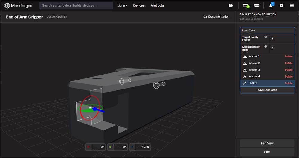
The direction and total force for a Load is quick and easy to modify using the associated widgets and value fields.
While setting up a Load Case, users also have the option of configuring their Target Safety Factor and Max Deflection in millimeters.
In the context of Simulation, the Safety Factor is a multiplicative figure for how much a part must exceed the expected load. For example, the illustration above shows that our part is expected to experience a 150N load. With a Safety Factor of 2, Simulation will treat the part as if it should withstand a 300N load.
On the other hand, Max Deflection will define how much a part should deflect or otherwise move while under load. This will generally be a low figure for parts that are supposed to be stiff. In this blog, we have set our part to have a two-millimeter maximum deflection.
When a Load Case has been completely configured and saved, users can next Validate their part to confirm whether their current print settings are valid for the Load Case that was just configured.
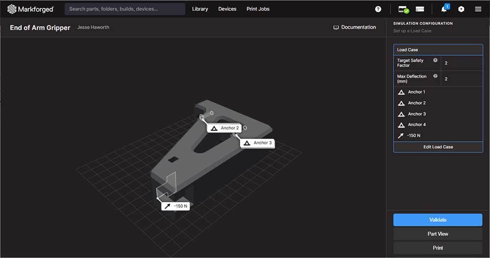
An example of a fully configured Load Case. When a Load Case is saved, users can then check their current print settings against the set requirements by selecting Validate.
Optimize Settings Before Printing
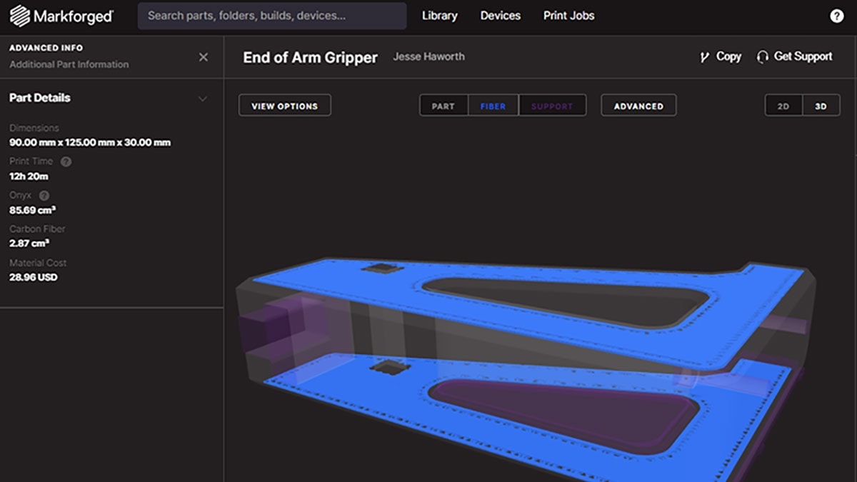
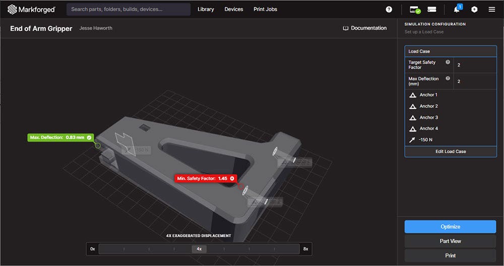
After the first pass validation, Simulation will show users both the maximum expected deflection and the anticipated safety factor based on their Load Case. An Exaggerated Displacement slider also becomes available to help visualize how a part will deflect, if at all.
An initial part validation will show users if their part meets or falls short of their Target Safety Factor and desired Maximum Deflection. The Exaggerated Displacement slider can also help visualize deflection.
Regardless of the results here, Load Case validation will next give users access to the second part of Simulation which is Print Optimization. Even if all targets are met or exceeded, it is always possible that the part could be improved in terms of print time, material usage, or strength. Optimizing a part via Simulation will take the guesswork out of print settings and automatically show users multiple different options for printing the part based on their requirements.
Part optimization can be quickly started by selecting the Optimize option available after part validation.
In the example of the end-of-arm gripper that we have shown throughout this blog, our desired targets have not been met by our current print settings, so our next step is to Optimize the part. Because Eiger is cloud-based, Simulation does not take a large amount of local hardware to run, and we can navigate away from the browser tab to work on other projects while our study runs.
When a part Optimization is fully complete, we are given several new part configuration options to review. The available results will be part and Load Case dependent, but these could include categories such as fastest Onyx-only print, lowest cost settings, and Continuous Fiber reinforcement for higher strength.
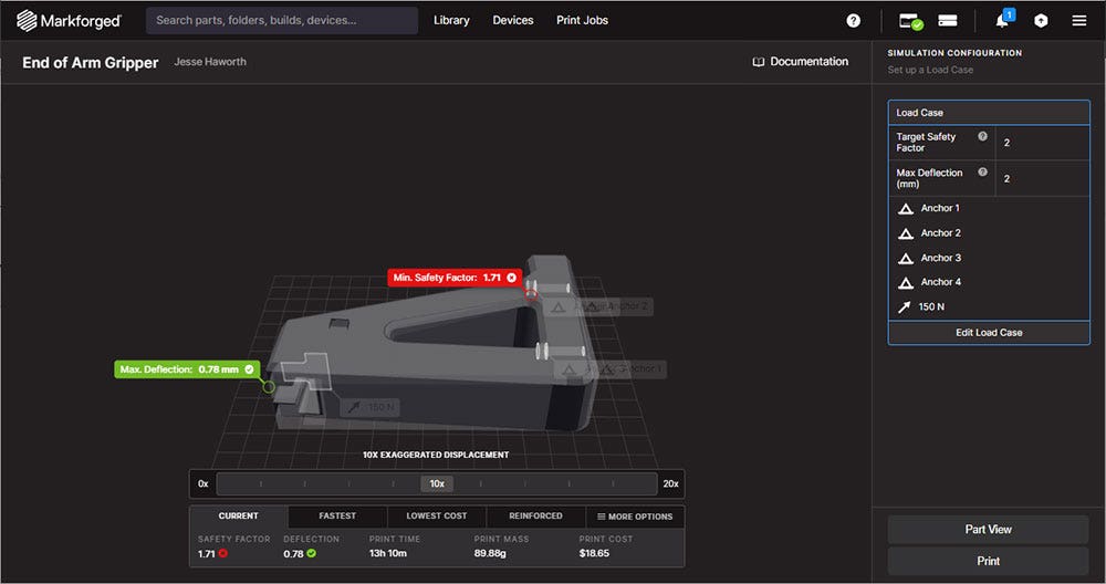
A finalized optimization will give easy access to different print categories and how they will perform under the defined Load Case.
Each presented category will show how the part will perform if printed with that specific optimization.
To view a more detailed list, the More Options button can be selected to compare each optimization. Simulation controls many different print settings such as infill, number of outer shells, and even continuous fiber patterns. Once the preferred setup is chosen, clicking Apply will re-slice the part with the Simulation optimized print settings.
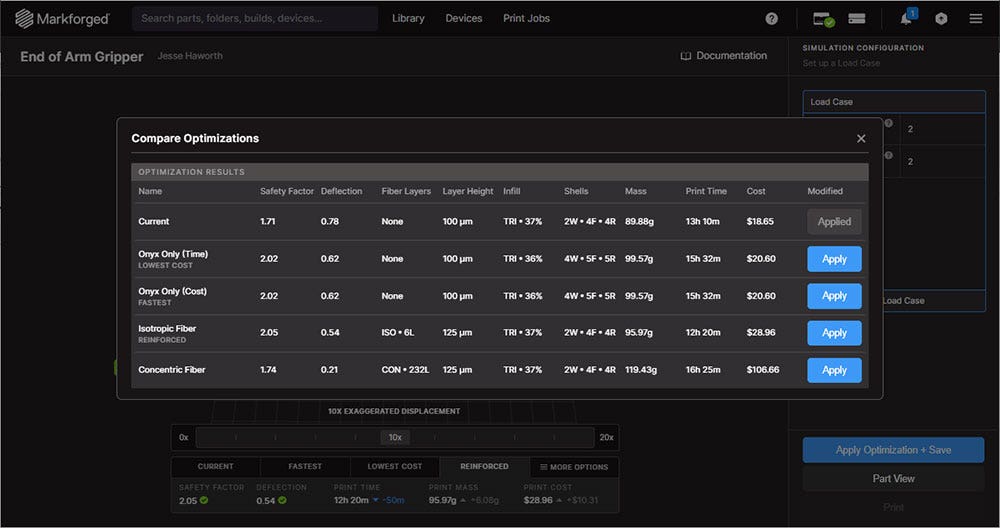
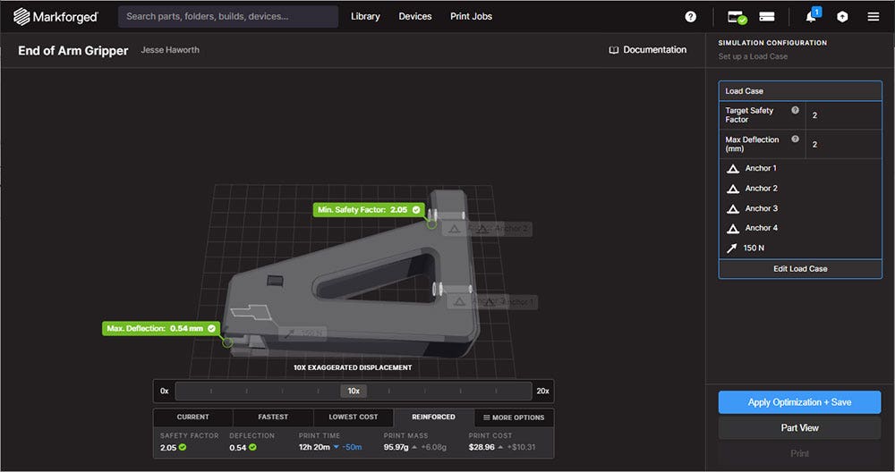
An example of different Simulation optimized results and how they will perform. Users can quickly get any option ready to print by selecting Apply.
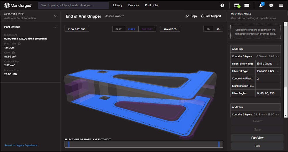
A ready-to-print part after being Simulation optimized based on our expected Load Case. The software gave us the option of printing a stiffer, faster part with Carbon Fiber even if we didn’t have it enabled during our first pass.
Markforged Simulation Resources
As mentioned at the beginning of this blog post, Markforged Simulation currently works with both Onyx-only parts and Carbon Fiber-reinforced Onyx parts. Since Simulation is a software solution, this material compatibility means that users with any of the Markforged plastic printers can make use of Simulation regardless of generation. Markforged will also release compatibility with different materials in future updates.
Simulation can optimize any new part upload or any part that is re-sliced after the software is activated.
Check out some of our other troubleshooting and how-to guides for Markforged in our knowledge base:
- Troubleshooting Poor Part View Performance in Eiger
- Exporting an Eiger Print Job for Offline Printing
- Updating an Offline Markforged Printer or Sinter
- How to Retrieve Markforged Printer Logs
Thanks for joining us for this walkthrough of the new Markforged Simulation software! The ability to simulate “as-printed” geometry is extremely exciting and we can’t wait to see how operators optimize their parts with it.
Check out our site for more information on Markforged 3D printers, and if you have any questions, be sure to contact us at Hawk Ridge Systems today.