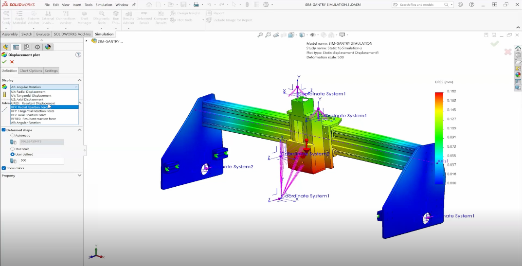
When performing a topology optimization in SOLIDWORKS Simulation an option is available to use something called the Min Max Formulation. This is relevant when optimizing a model with multiple load cases. But what is Min Max and when should it be used over the standard formulation?
Note: This article assumes you’re already familiar with Topology Optimization studies using multiple loads. If you’re not, check out how to set up such a study.
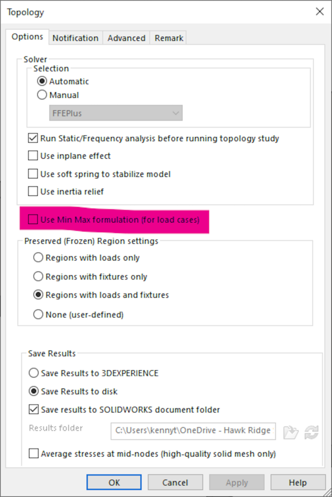
To use the Min Max formulation, right-click the study and go into its properties to select it.
When to Use Min Max versus Standard: An Example Use-Case
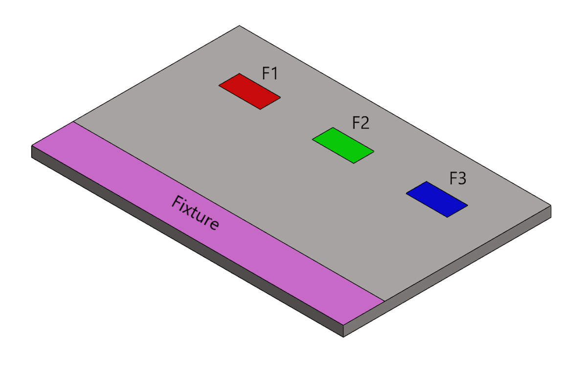
Consider the metal plate shown above. It will be fixed from the purple face, and forces of 50 N, 30 N, and 90 N will be applied to the red, green, and blue faces, respectively. The topology optimization studies will attempt to maintain the best stiffness-to-weight ratio while removing 30% of the existing material. One study will use the standard formulation, the other will use the Min Max formulation.
Here is the top-down view of the plate after topology optimization using the standard formulation:
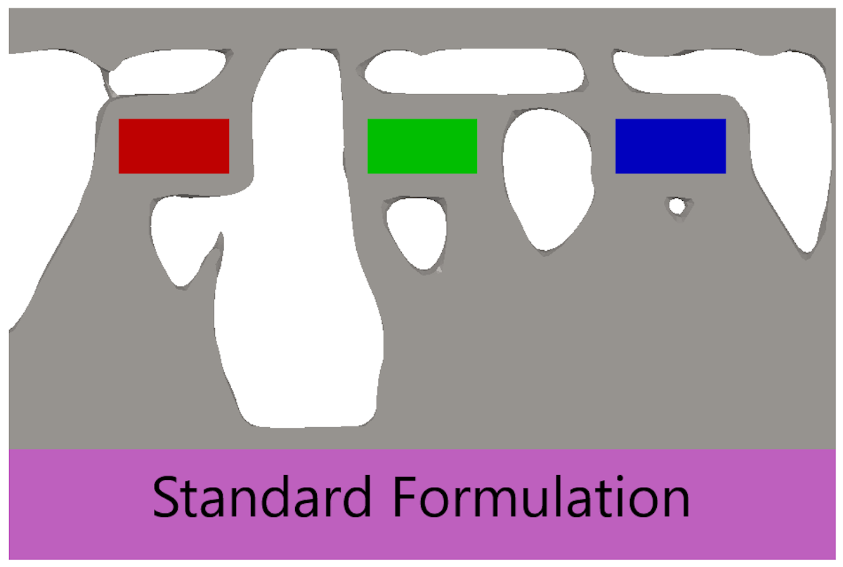
Here is the top-down view of the plate after topology optimization using the Min Max Formulation:
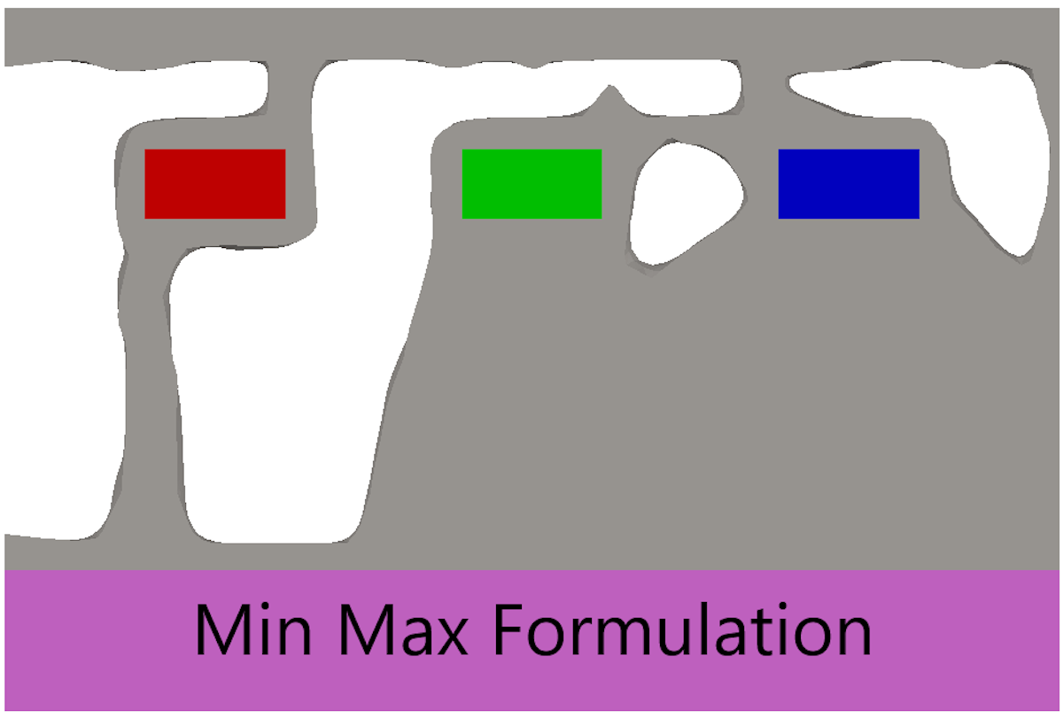
It’s clear that the two plates are slightly different, but let’s dive deeper by measuring their maximum displacements* under different loading conditions. Each plate will be subjected to four loading conditions, F1 only, F2 only, F3 only, and all loads combined.
*The two formulations are technically focusing on compliance and not displacement. However, the two are directly related to any single loading condition.
Compliance is the reciprocal of stiffness and describes the ratio of displacement to loading forces. Higher compliance results in greater displacements at the same force.
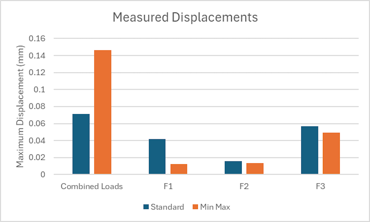
Looking at the Combined Loads condition, the standard formulation plate appears about twice as stiff (half the displacement). However, when subjected to loads F1, F2, and F3 individually, the Min Max plate is stiffer (or has less displacement) than the standard plate in all three cases. This drills down to the fundamental difference in the goals of each formulation:
The standard formulation seeks to produce the smallest cumulative compliance/displacement for each load case, which translates to the stiffest possible structure when multiple loads are applied simultaneously, while the Min Max formulation seeks to produce the stiffest structure for each individual load case, without regard for what the total compliance may be.
So, How Do You Know When to Use Min Max Formulation Versus Standard?
Math and theory aside, to a more practical matter: When should each formulation be used?
When optimizing a part with multiple loads for stiffness-to-weight ratio, ask yourself: Will the different loads happen separately? Or will they happen simultaneously?
If the loads are expected to occur separately, use the Min Max formulation. If the loads are expected to occur simultaneously, use the standard formulation (default).
For more information on topology optimization in SOLIDWORKS Simulation, check out the following articles: SOLIDWORKS Simulation: Exporting Topology Results and An In-Depth Look at SOLIDWORKS Topology Optimization.
For more questions about topology optimization in SOLIDWORKS Simulation, get in touch with Hawk Ridge Systems.


