In recent years, SOLIDWORKS Simulation Professional added a brand new study called Topology. If you have ever taken a look at the Topology study in SOLIDWORKS Simulation Professional, you may have been excited about its ability to create optimized shapes by removing material from a part. This helps reduce weight while maintaining material in critical areas needed to meet design requirements. In this post, we’ll cover how the Load Case Manager available for Topology and Static studies in SOLIDWORKS Simulation Professional can allow you to optimize a shape for multiple loading conditions.
Project Overview
I came up with the idea of trying to convince our digital manufacturing team to print me a skateboard. My plan for this project was to make a small board, just big enough to ride around our business park.
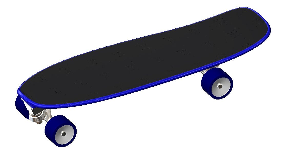
I immediately turned to the Topology study for a number of reasons. The skateboard was going to have to be very strong for its weight, obviously so that it could hold my weight, but also because reducing the material volume as much as possible makes it faster and cheaper to print. Keeping this economical would help me to convince our digital manufacturing team to print this silly – er, I mean serious – project of mine. As an added bonus, why not make it look awesome? In my opinion, optimized shapes bordering on the look of alien technology are pretty dang cool looking.
What Are We Covering?
We are going to tackle optimizing for the best stiffness to weight ratio using the Topology Study in SOLIDWORKS Simulation Professional. Instead of focusing on all of the available options in the Topology Study (check out this video for details on topology), I want to focus in on the first problem I ran into when trying to generate my cool looking skateboard – multiple loading conditions.
How Can the Load Case Manager Help?
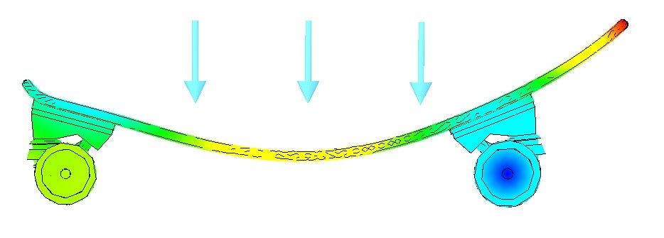
When cruising around on a skateboard, you utilize two main stances: one for pushing and one for riding. While pushing, a single foot is situated near the middle (or toward the front) of the board and your entire weight has to be supported.
When you’re in your “cruisin’ stance,” weight is distributed across both feet, one of which usually rests on the tail of the board.
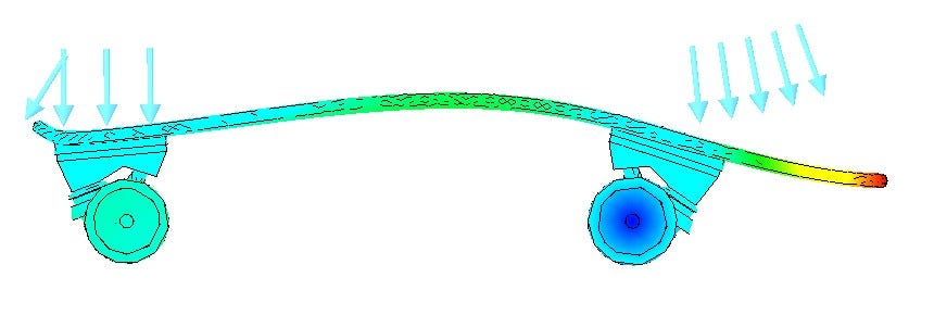
These two different loading conditions flex the board in different directions, thus changing which sides are in compression and tension. For our Topology study, utilizing both as a combined load wouldn’t be the most realistic representation as these two loading conditions would work toward canceling each other out. This is where the Load Case Manager (available in SOLIDWORKS Simulation Professional) comes into play.
What Does the Load Case Manager Do?
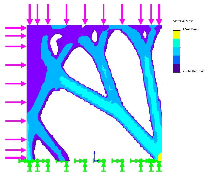
In order to simply demonstrate this approach, we will first take a look at a very simple example: a flat plate loaded from two different directions and fixed on the bottom.
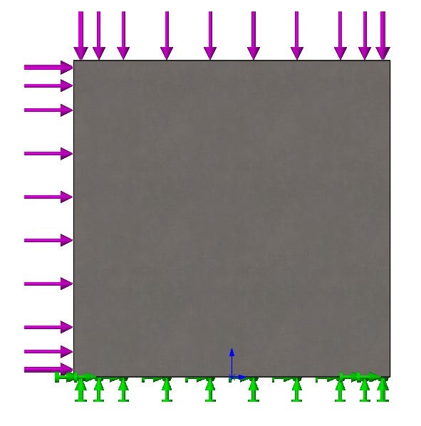
Before we get to the Load Case Manager, let’s take a look at how Topology would handle each load case individually. First, when loaded from the top, we get results very reminiscent of classic bridge designs.
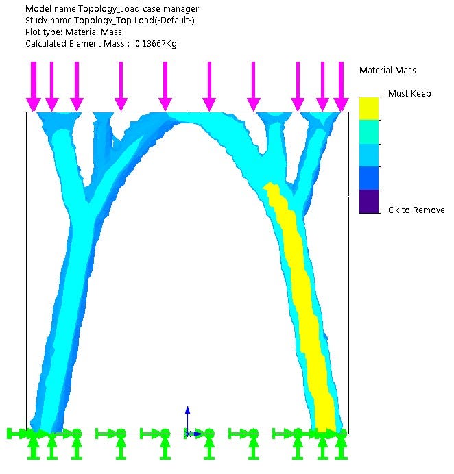
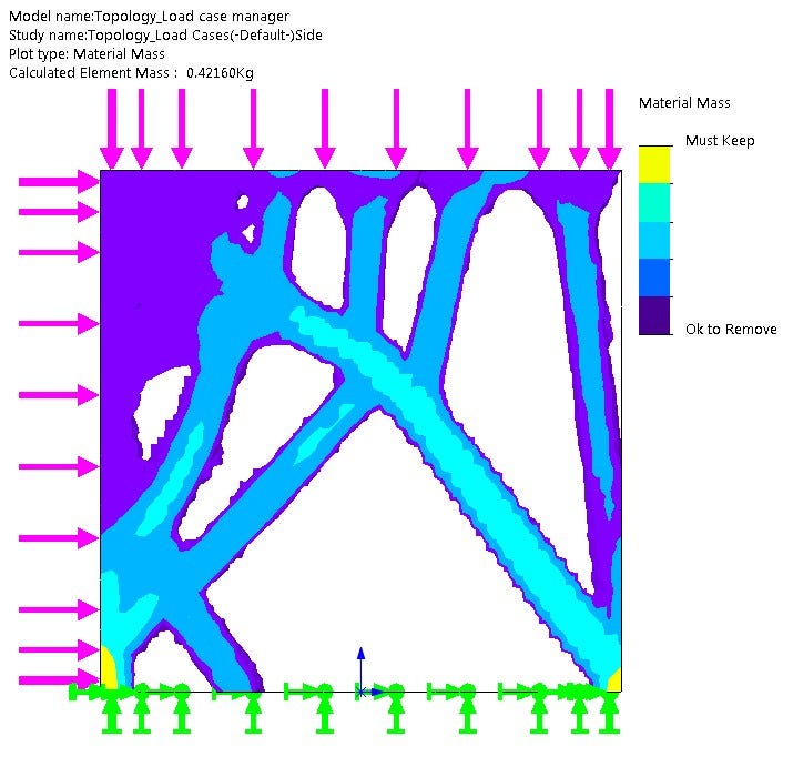
Then, when loaded from the side, we get an entirely different structure.
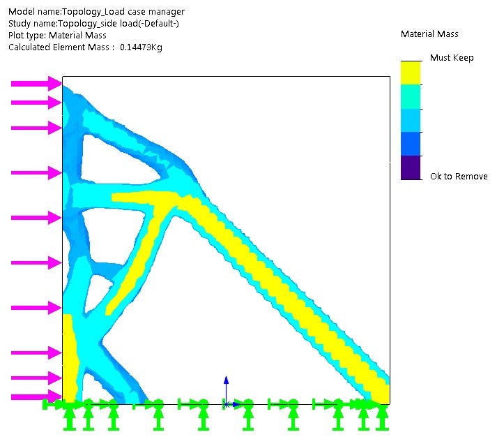
The results from these initial tests do indeed show what look like useful insights when designing for the respective loading conditions, but it is not necessarily obvious how a structure could best integrate elements from both results. What about the case of combined loading, loading both the top and side simultaneously? Though that would not work for our skateboard, in many cases this would seem to be a viable solution, so we will also test that to serve as another base of comparison for our Load Case Manager study.
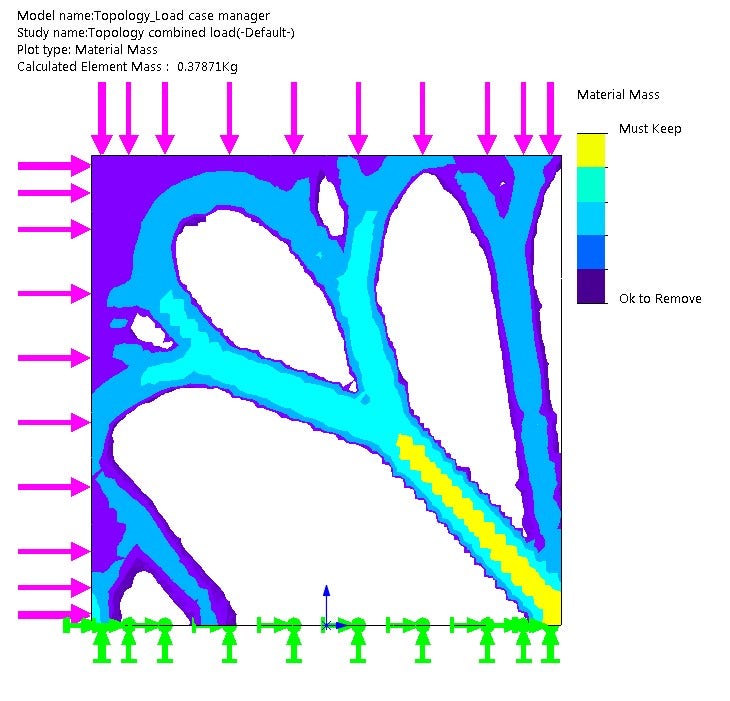
The results from the combined loading look great, but what if the two loading conditions never happen simultaneously? The Load Case Manager Study allows us to define scenarios where each load acts individually.
How to Use the Load Case Manager
Setting up the Load Case manager is very simple. First, set up a single simulation study (in our case Topology) that has every load and fixture needed for all loading conditions.
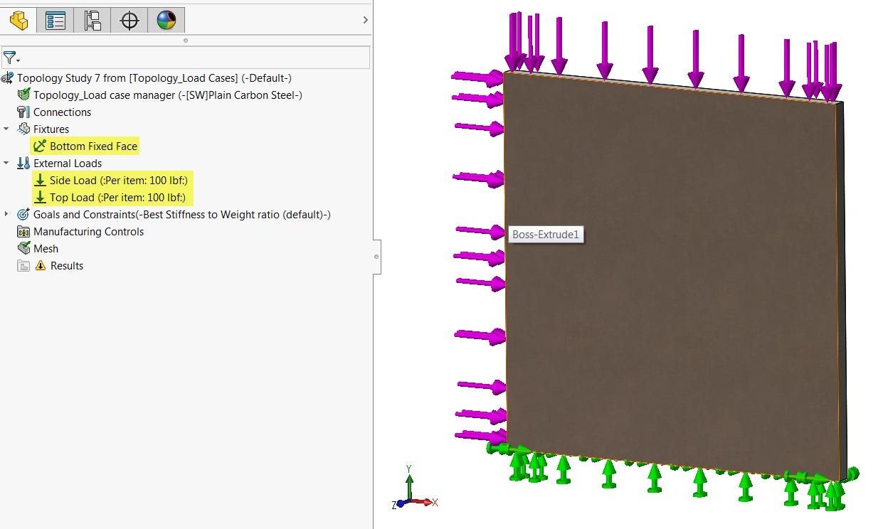
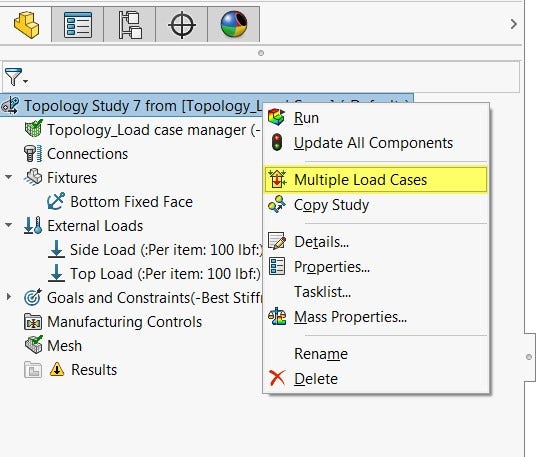
Next, I will right-click at the top of the study tree and select Load Case Manager.
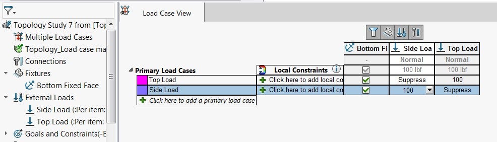
Then, set up different load cases by clicking the “plus” button, typing a name, and unsupressing the appropriate loads and fixtures. Finally, just click Run This Study.
Results from the Load Case Manager
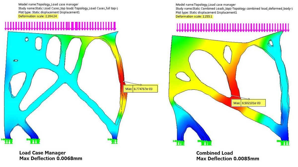
The results we get from this study look very different compared to the combined loading case. In order to accurately validate which will be stronger, standard Linear Static studies must be run on the new plates that are redesigned based on the Topology studies.
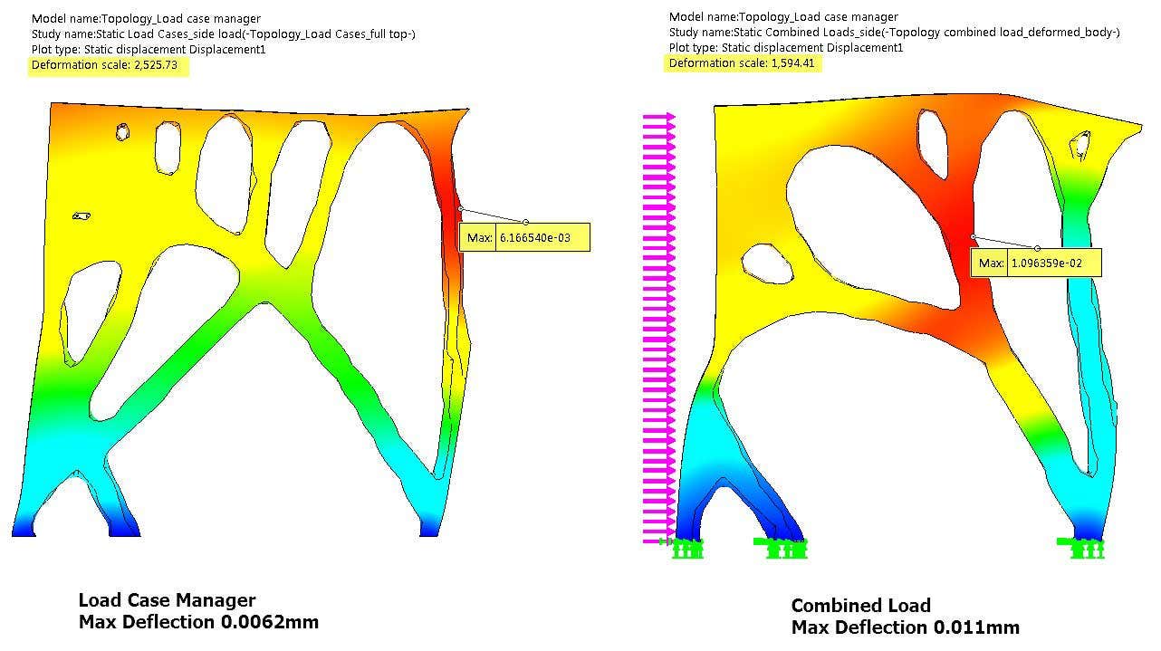
After exporting the results and setting up Static studies it is clear that the Load Case Manager study is indeed stronger for the individual loading conditions.
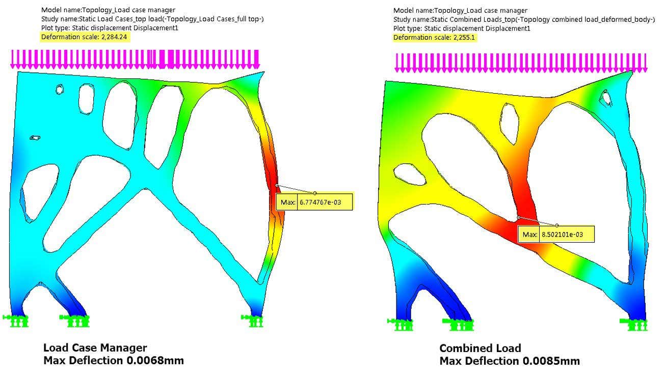 Adding a third combined load case still keeps the Load Case Manager design stronger overall.But if we also want to take into account the combined loading the we can add a third load case describing the combined loading and run the study again. The result is very similar to the combined loading result, but now stronger for all three cases!
Topology Optimized Skateboard
Now let’s see how this process played out for the skateboard! First, just as a reference, I ran Topology studies for each individual loading conditions.
Mid-board load:
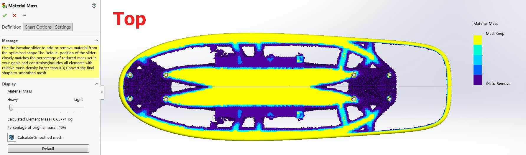
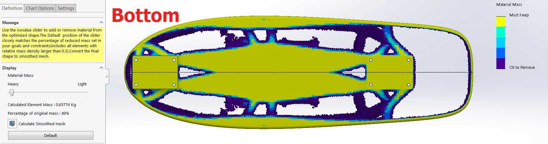
Nose and tail loading:
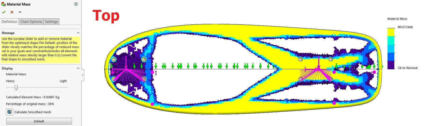
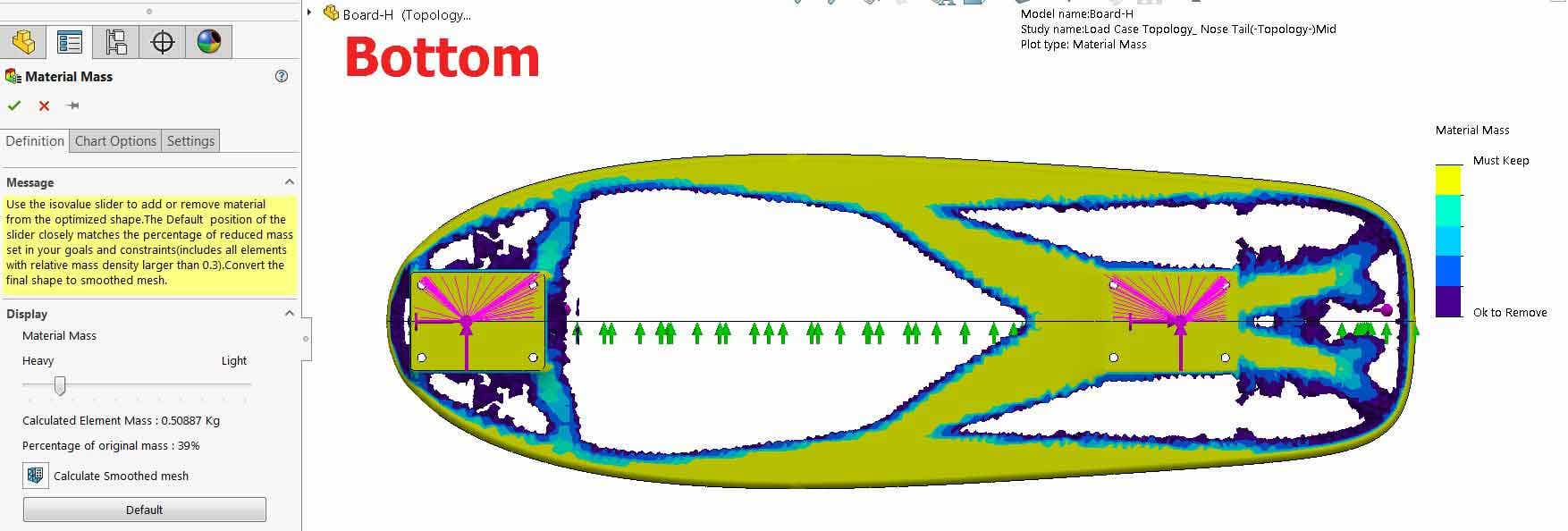
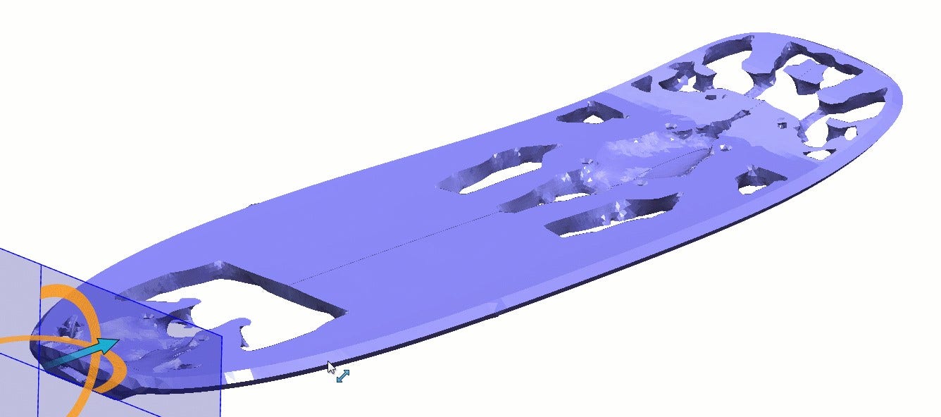
Load Case Manager:
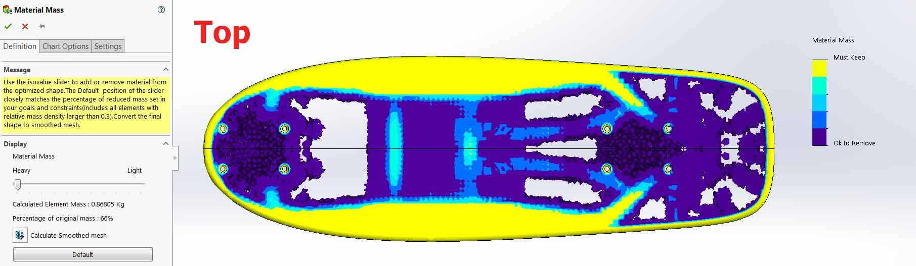
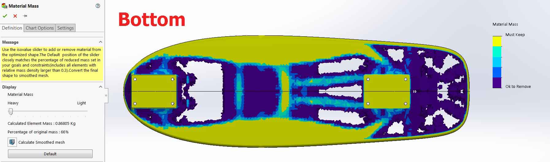
It should be noted that the results generated from the Topology study are best used as a 3D reference for making standard sketches and cut features, the mesh bodies themselves are rarely used as the geometry is fairly tessellated and can be difficult to clean up. I think based on the results that I got I will be taking this back to the Load Case Manager to include some loading to the side rails of the board so that torsion can be taken into account as well.
In this blog we took a look at how the Load Case Manager expands the capabilities of the Topology Study by allowing you to define separately applied loading conditions. While we were focused on the Topology study, the Load Case Manager is also available for Linear Static studies as well!
Check out our website for more in-depth information on SOLIDWORKS Simulation and if you have any questions, contact us at Hawk Ridge Systems today. Thanks for reading!