In this article, we’ll show you how to use the Parting Surface command in the SOLIDWORKS mold-making process. Before using the Parting Surface command, the part should be ready for mold making (proper draft angles, scaled to account for shrinkage, etc.) and the parting line should be created. You can read more about how to create the parting line in this parting line tutorial.
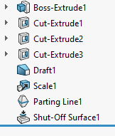
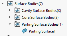
While shut-off surfaces and parting surfaces should both be created after the parting line, the specific order between the two is not important. In this example, the shut-off surfaces have already been created. Below you can see the state of the tree before you create the parting surface. The part has been drafted, scaled, and had a parting line and shut-off surfaces made.
The Parting Surface’s purpose is to separate the mold halves around the model, while the shut-off surfaces separate the mold halves within the model.
Launching the Parting Surface Command in SOLIDWORKS
The Parting Surface command can be found on the Mold Tools tab of the CommandManager or under Insert>Molds>Parting Surface.
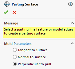
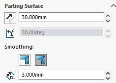
Launch the Parting Surface command and select the “Perpendicular to pull” option under the Mold Parameters. This determines the angle of the parting surface and is usually suitable for most models. There are two other options: “Tangent to surface” and “Normal to surface.” For many models, choosing perpendicular to pull is appropriate.
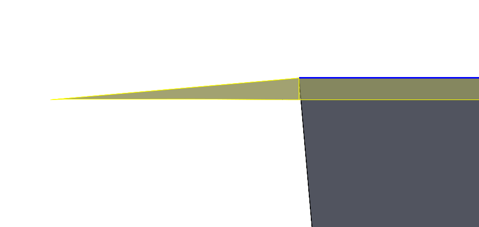
Pictured below is what the preview looks like from the side with the perpendicular to pull option. The tangent to surface option would also create this same orientation.

Below you can see what the preview looks like with the normal to surface option. The parting surface is normal to the drafted wall of the part which causes it to angle downwards.
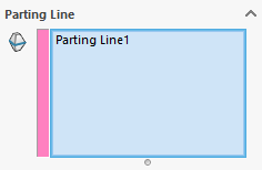
Under the Parting Line selection box, select the pre-existing Parting Line feature in the model if it isn’t already selected. Typically, it’s selected automatically when there’s only one parting line feature to choose from.
Under the Parting Surface section, the distance the surface extends can be added. The distance should be large enough that the tooling split sketch made in the next step fits entirely within the parting surface. For this model, 30 mm is plenty.
The option to control the smoothing, which will not apply to this surface because it is planar, is shown in the photos below toggled off and then on. Smoothing can help reduce machining costs associated with sharp edges in the parting surface. Set the size of the parting surface here, as well as the smoothing (if applicable).
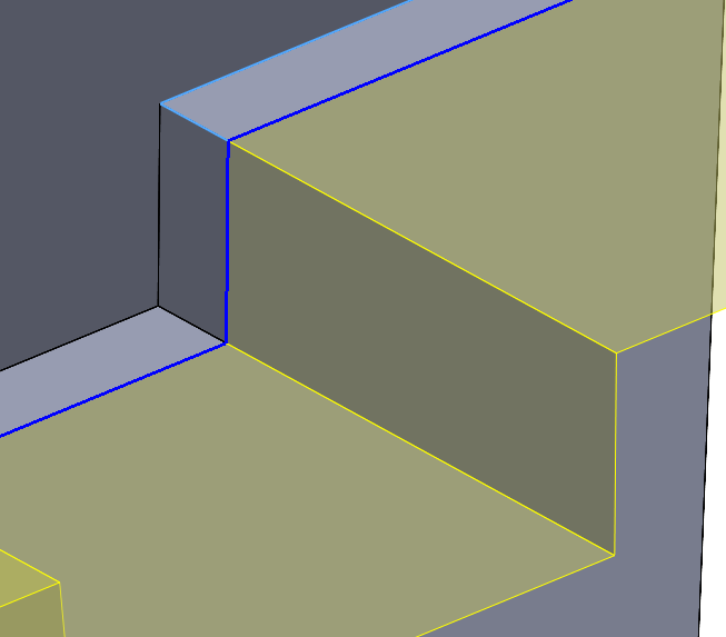
The part below has bends in the parting surface. Here you can see the sharp corner with smoothing turned off.
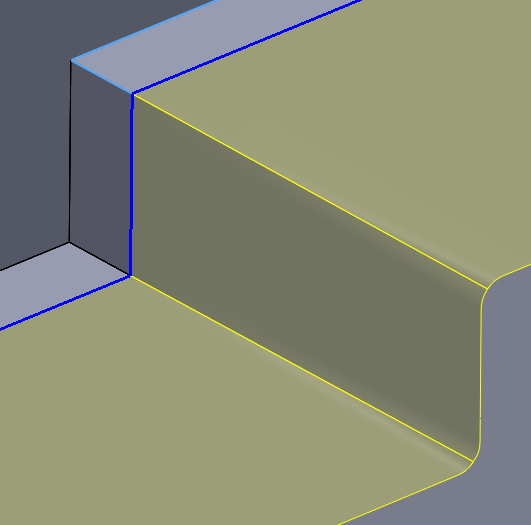
Pictured below, this part has smoothing turned on, and you can see the sharp corner develops a fillet, which can ease machining.
After clicking ok to complete the command, the parting surface will be created as well as a folder for the parting surface bodies.
Conclusion: The Parting Surface Command in SOLIDWORKS
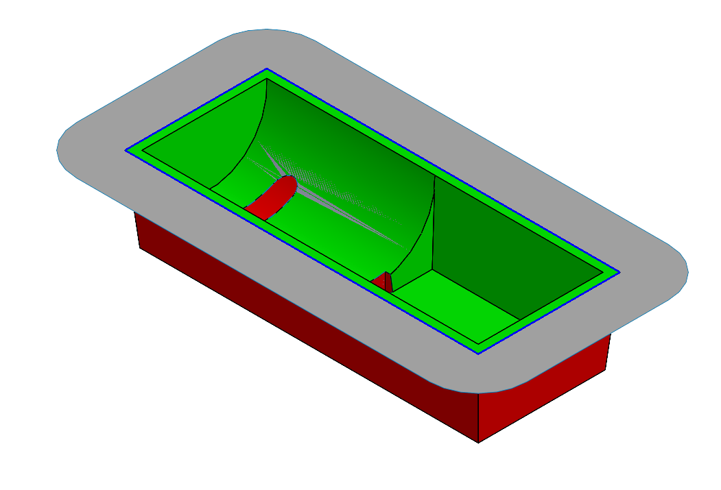
The parting surface is pictured above in gray. Now that the Parting Surface has been completed, the next step is to create the mold halves using the Tooling Split command.
Need more help with the mold-making process? Check out the mold design course in SolidProfessor, included in your Hawk Ridge Systems Essential or Elite subscription or get in touch with Hawk Ridge Systems.