
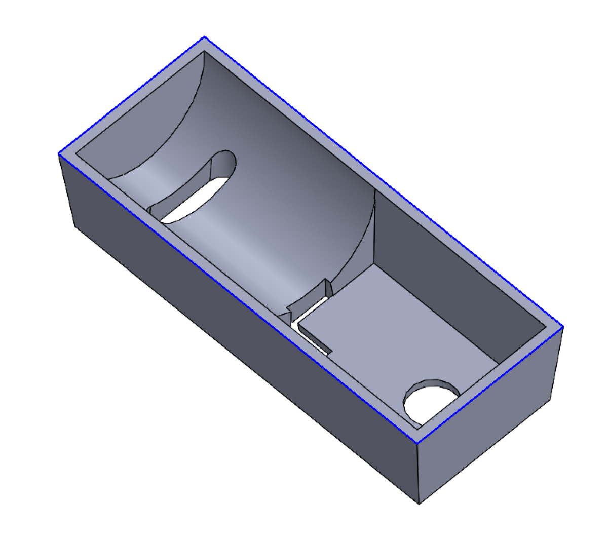
This article will discuss how to use the Shut-Off Surface command in the SOLIDWORKS mold making process. Prior to using the Shut-Off Surface command, the part should be ready for mold making (proper draft angles, scaled to account for shrinkage, etc.) and the parting line should be made.
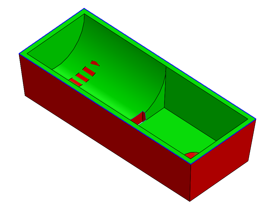
The Shut-Off Surfaces’ purpose is to close any through holes in the part so that two knittable surfaces can be generated in the model, one on either side of the parting line. These surfaces represent the cavity and core sides of the mold.
How to Use the Shut-Off Surface Command in SOLIDWORKS
Selecting Loops
When the command is first launched, it will automatically attempt to select all through holes in the part. For simple geometries this will work, but for more complex parts it may make mistakes such as: selecting extra loops, omitting some holes, or simply choosing a less desirable loop around a complex opening where multiple loop options exist.
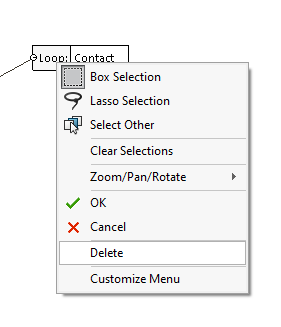
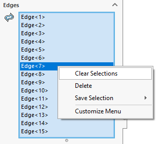
To remove an individual loop, right click on the callout in the graphics area and choose Delete. To remove all loops right click in the edge selection box of the PropertyManager and choose Clear Selections.
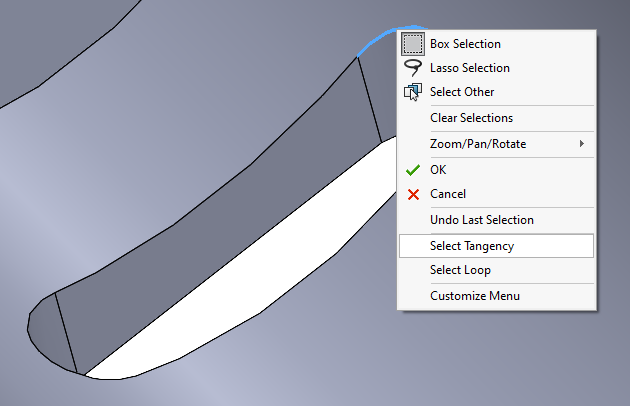
When selecting loops manually, the edges can be selected one at a time from the graphics area, or two common shortcuts can be used. For loops of tangent edges, right click one edge of the loop and choose the option Select Tangency to select the entire loop at once. For non-tangent loops, select one edge of the loop and look for the red arrow at one end of the edge. Hit the Y key on the keyboard to select the next edge indicated by the arrow or hit the N key on the keyboard to toggle the arrow direction to another edge.

Pick the Fill Type
After the loops have been selected, there are three different fill types to choose from for each loop. The fill type will depend on the specific geometry of the opening. The fill type of a loop can be changed between the three options by clicking on the callout in the graphics area. The fill type of all loops can be changed by hitting the respective button in the PropertyManager.

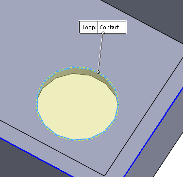
The Contact Fill Type
This is the simplest fill type and will generate a surface patch that contacts the loop edges. It is most used for basic round through holes in planar faces.
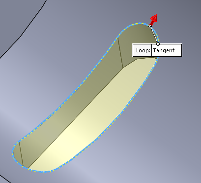
The Tangent Fill Type
The Tangent fill type generates a surface patch that contacts the loop edges, but is also tangent to the faces of the opening. It is useful for more complex openings and openings that go through curved faces. There will be an arrow that appears next to the loop in the graphics area when tangent fill is selected. Click on this arrow to toggle which set of faces the patch is tangent to.
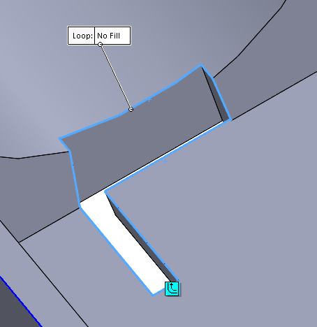
No-Fill
The No-Fill fill type is usually the least used and is reserved for the most complex openings where contact and tangent fills cannot generate a satisfactory patch. No-fill still requires a loop selection because it lets SOLIDWORKS know you will be constructing your own manual surface patch inside that loop. Even in a part where all openings will be manually patched, you still need to run the Shut-Off Surface command and indicate all openings as no-fill. That’s because SOLIDWORKS still generates surfaces for the rest of the model faces, and not just for the patch areas. By using no-fill, the surfaces will generate up to the boundary of the loops and left open to match up with your manually constructed patches.
Finishing Up
Once all the holes have been closed off in the model, the PropertyManager message will change to green and the command can be completed.
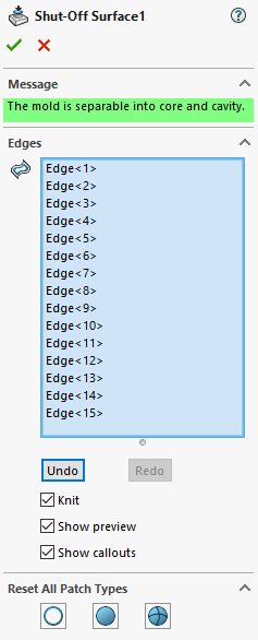
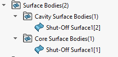
The command will then create Core and Cavity surface folders if they don’t already exist and populate them with the surfaces.
Final Steps on How to Use the Shut-off Command in SOLIDWORKS
Now that the Shut-Off Surface command has been completed, the next step is to manually patch any complex openings (if they exist) that were marked as No Fill.
While this article shows the typical process for working with the Shut-Off Surface command, it can sometimes get stuck even when the proper user selections have been made.
Have more questions about how to use the shut-off surface command in SOLIDWORKS? Reach out to Hawk Ridge Systems today to talk to one of our experts.