
This article will discuss how to use the Parting Line command in the SOLIDWORKS mold making process. Prior to using the Parting Line command, the part should be ready for mold making (proper draft angles, scaled to account for shrinkage, etc.).
But first, what’s the purpose of the parting line? The Parting Line separates the outer perimeter of the model into a core side and a cavity side. The Parting Line will be used later to create the Parting Surface (which separates the mold halves around the model), as well as help create the Shut-Off Surfaces (which separate the mold halves within the model).
Creating a Parting Line
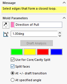
The first step to create a parting line is to identify the direction of pull for the mold. This can be a plane, planar face, or linear edge. You’ll need to enter the draft angle in this direction, then hit the draft analysis button.
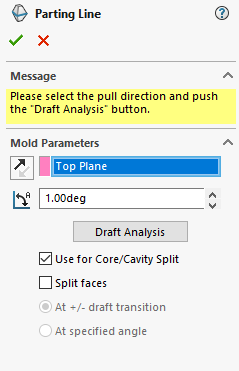
The checkbox “Use for Core/Cavity Split” should be checked. The “Split faces” checkbox can be left cleared for this example.
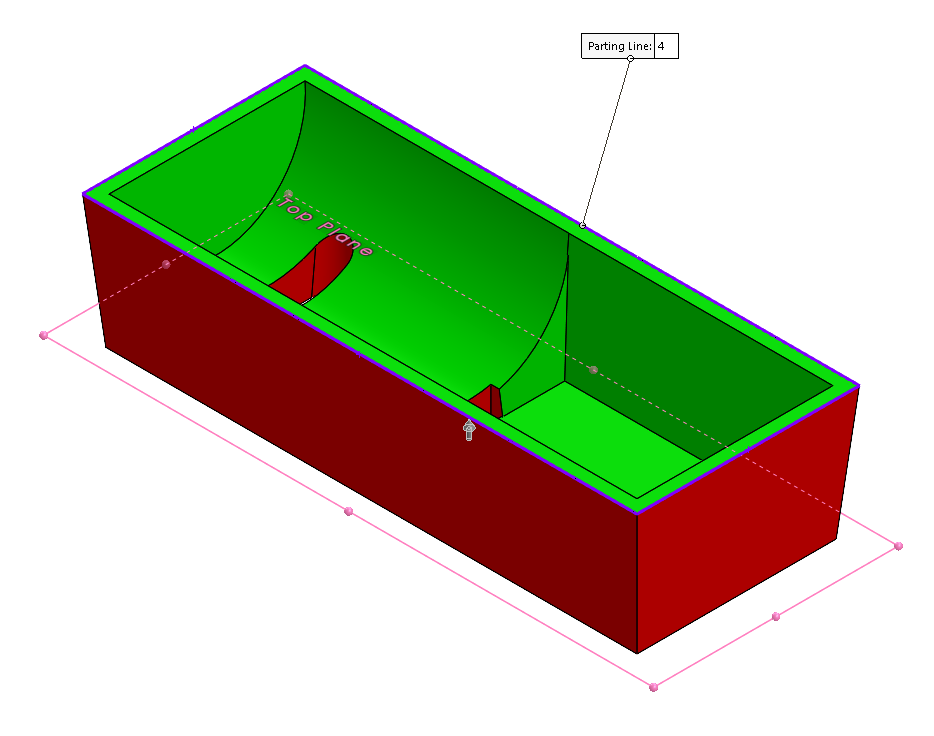
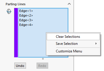
The command will perform a draft analysis of the part using the specified draft angle and direction of pull. It will then attempt to automatically select edges to form a parting line loop. It does this by finding the edges between the positive and negative draft faces (green and red faces). For simple parts this will work easily, for more complex parts a manual selection will need to be done.
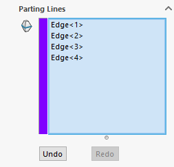
To perform a manual selection, right click inside the parting lines box and choose clear selections, then manually pick the edges you wish to form the parting line.
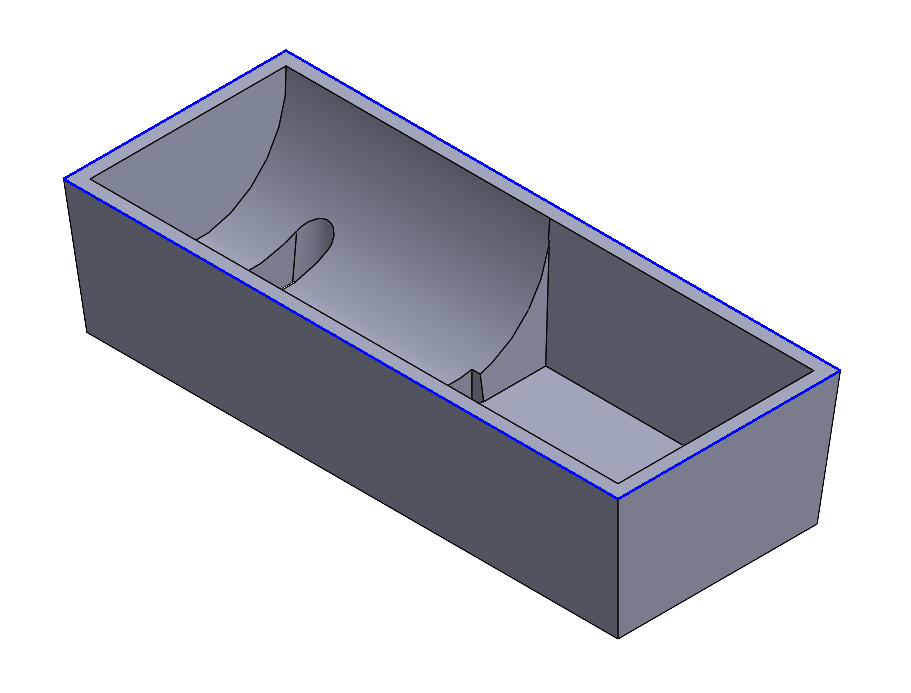
Click on the Ok button to finish the command, and the parting line will be shown on the part. In the next example, you can see the final result, with the parting line represented with blue.
Split Faces to Deal with Straddle Faces
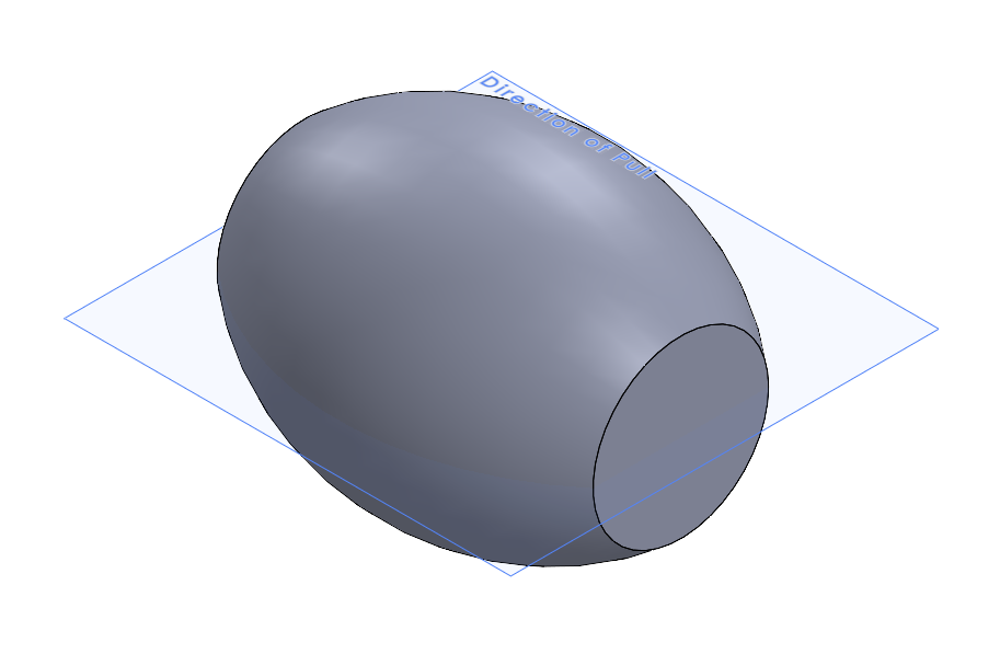
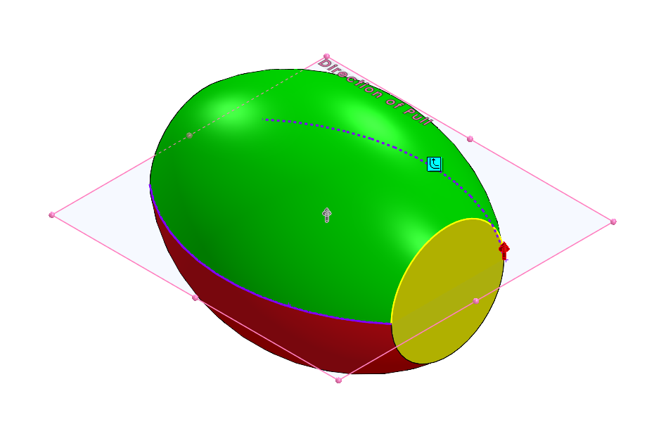
For certain parts, there will be straddle faces. These are faces which transition from positive to negative draft without an edge in between. To deal with straddle faces, the split faces option can be used. This is shown with the roller part below. In this example, the plane bisecting the part is the direction of pull.
The Parting Line command is run as usual, but because of the lack of edges, a parting line cannot be found. For reference, the desired parting line will be four total edges, running in a planar loop through the poles of the part within the blue plane.
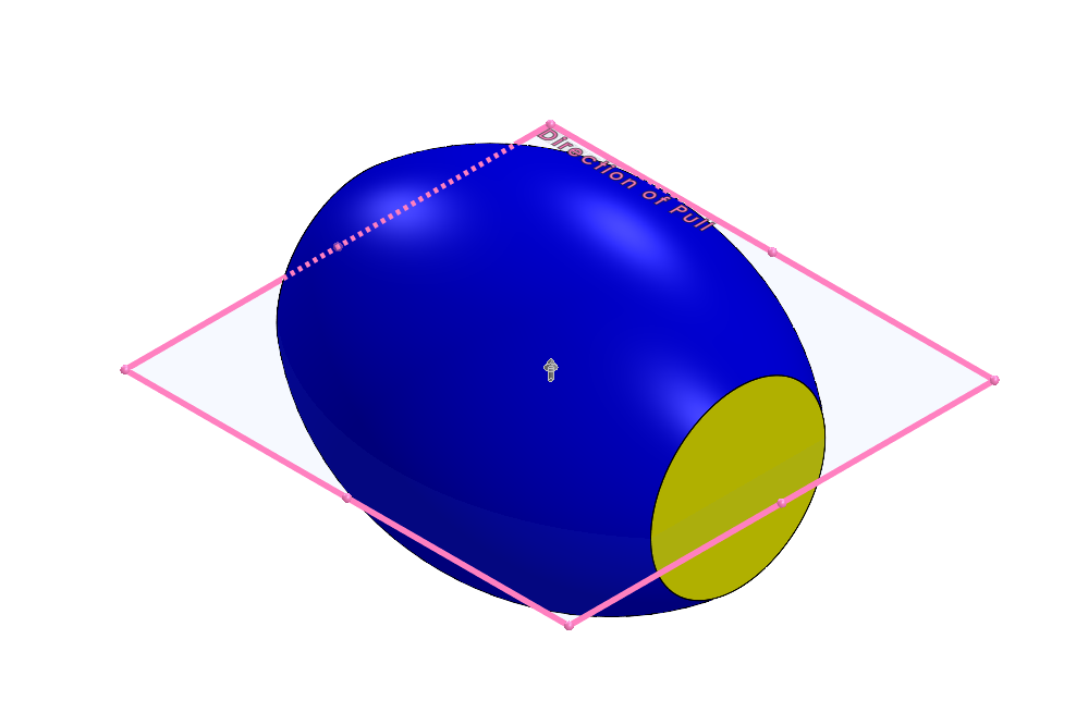
In this instance, blue means straddle face, and yellow means a face with no draft. To split the blue straddle face and generate edges that can be used for the parting line, the Split faces option is enabled. This will split the blue face into two faces, with the location of the new edge at the transition between positive and negative draft. You then need to check the Split faces box and choose the option at +/- transition.
The two new edges are then selected in the graphics area to use them for the parting line. This generates two new edges, resulting in a positive face and a negative face, instead of one single straddle face.
That’s half of the parting line, but it’s still not able to cross the yellow faces at either pole because they are perfectly flat, and have not been affected by the split faces option. They can be dealt with using the Entities to Split selection box in the next step.
Using Entities To Split
The Entities To Split box is found at the bottom of the Parting Line PropertyManager. To use it, simply select two vertices between which you want to split a face. Here, the two vertices on opposite sides of the yellow face will be selected.
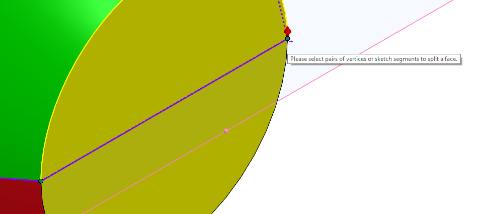
This splits the face in a straight line between the two vertices and automatically selects the new edge for the parting line. Then, you’ll simply repeat the process for the opposite side.
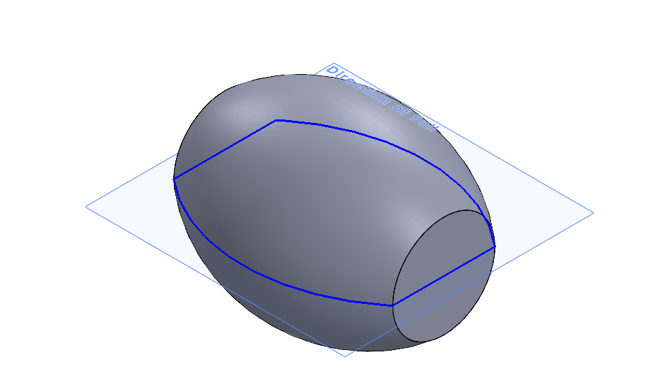
The final parting line will be composed of two arcs and two straight edges, none of which were present before starting the Parting Line command.
Note that in this example, the Split Faces option and Entities to Split option were shown working together. These options can be used independently or together, depending on the specific geometry of the problem. Now that the Parting Line has been completed, the next step is to create Shut-Off Surfaces, if necessary, and create the Parting Surface.
More Help Using the Parting Line Command in SOLIDWORKS
We hope you found this parting line tips and tricks article helpful. Still have questions? Reach out to Hawk Ridge Systems today.