So you’ve got your mill setup, you’ve ordered all of your tools, vises, and holders. Let’s not discuss how much you’ve just sunk into ‘ancillaries’ to get this venture, AKA hobby, going. Wipe that brow, take a sip of that brew, and let’s talk tooling. Whilst you can just adjust tools on the fly, from a productivity standpoint, it just makes sense to take a little bit of time to get that tool drawer synced up with SOLIDWORKS CAM. And that’s what we’re going to walk you through here.
Learn How to Set Up Your Tool Crib in the Technology Database in SOLIDWORKS CAM
If you’re more of a ¼ mile than a Bonneville type of person, look out for the traffic signals highlighting the key areas to adjust and they’ll get you off the line and into victory lane ASAP.
![]()
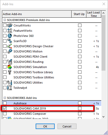
Let’s get that tooling setup so you can start raking in the Benjamins, or at least paying off that credit card bill so you don’t have to rush out to greet your postman/woman each month. Your first task of the day, should you choose to accept it, is to fire up your SOLIDWORKS and check on the SOLIDWORKS CAM add-in from the Tools>Add-Ins menu.
Before we get into the meat and potatoes of it, let’s dispel some common myths/questions:
My tool numbers vary for each program, can I build a crib that is all of the tools that I own?
Yes. The tool crib in every part file is a localized version of the one in the database, so you can change the numbers in the part file or add tools to it without affecting the database version.
My machine always has the same tools in certain pockets, can I build the crib to match?
Yes. Simply set the tool stations in your tool crib, save them to the database and they’ll be preset. You’ll probably also want to link the Machine to the tool crib also.
Can the same tool have different feeds/speeds for different stock materials?
Yes. The tool can have cutting parameters associated with the stock material. Your feeds and speeds should be set to Tool.
I use different tools in different materials, can I build the tool cribs based on stock Material?
Yes, you can create multiple tool cribs, give them names specific to each material and select the crib when needed. The feeds and speeds can be linked to the tools as you’ll see later.
Do I need to add every tool I own?
No. You don’t have to go adding every single tool you own, though it may determine which of the options for Tool Crib Priority that you use. Whilst we’re here, let’s explain the implications of this!
![]() Tool Crib Priority:
Tool Crib Priority:
So you’ve dropped a whole bunch of cash on some decent tools, you want to use them, right? This will depend on the strategies you’re using as to how successful this will be. If your strategies are set to use a particular tool, then this setting won’t affect that. But if you’ve got it set up to use any ½” flat end mill or to pick from a range of sizes for example then this setting will force it to look in your tool crib to find an appropriate tool, before adding one from the database.
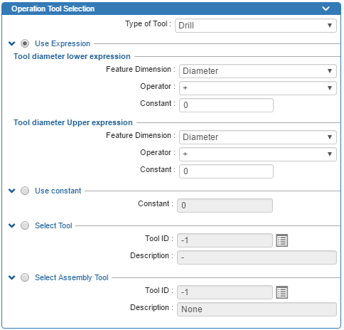
Tool Selection options from Features & Operations in Technology Database: Expression, Use Constant, Select a Particular Tool, Select a Particular Tool & Holder Assembly
Use Tool Crib Tools Only:
Sounds like something you want to be enabled, doesn’t it? After all, why would you want it to use tools that you don’t have?! Well before you get all click-happy, it’s probably good to explain the outcomes. Let’s use an example, say you want to drill a hole but you didn’t want to go adding every drill size under the sun into your tool crib. Since you didn’t add all your drills to the tool crib, it won’t generate that particular operation, so you’ll have to manually add that operation, define the parameters and select the tool. If you left this option unchecked, it would create the operation, but the tool may or may not be the one you want to use. Worst case is you’ll have to change the tool, less work than adding operations, setting parameters and selecting the right tool. And who wants more work?! Worth thinking twice on this one.
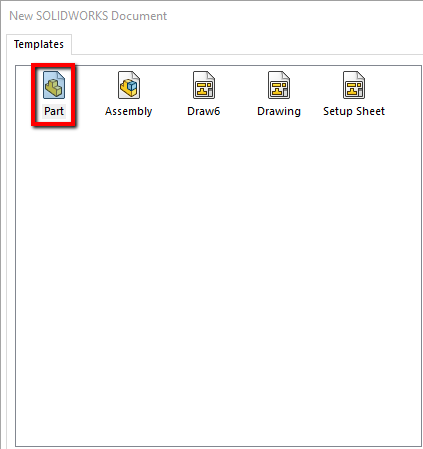
Enough talk, let’s take some action. Whilst the title does explicitly say, setting your tool crib in the Technology Database, we’re going to ignore that and go right ahead and build it inside SOLIDWORKS, so click on File>New and choose a Part file. Not only is it easier doing it in a part file as opposed to the database, by doing it in an empty file, we also prevent any complications of having an existing program. It can be done, you’ve just got to take more care ensuring that the tools are defined correctly and you’re saving the right ID in the database.
![]() Units:
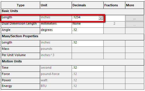
Units:
You can procrastinate all you want, but ultimately you’ll have to choose a preferred unit method. For some of you, this may be obvious, but for others who regularly deal with a mix of Metric and Imperial tooling, you’re going to need to choose. A straightforward way to decide is how do you want to enter feedrates or which do you use more frequently? If you use Inch more frequently, but occasionally get some metric holes, use Inch. You’ll be defining metric tools as an inch equivalent. Switch the Units to your preferred method using the drop down at the lower right corner or by going to Tools>Options>Document Properties> Units. You’ll also want to switch the decimal places. We’ll use Inches in our example, so adjust the units and set it to least 4 decimal places to prevent rounding of the numbers.
![]() Select Machine:
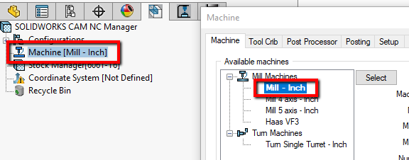
Select Machine:
In addition to the Units, above, ensure that you’re using a Mill that is defined in the correct portion of the database. Double click the Machine to open the dialog and double-click on one of your machines. We’ll use the default Mill-Inch machine in this example. And to answer your question, no. It doesn’t matter which machine you use, so long as the units are correct.
For those of you who want to link the tool crib to a particular machine check out the other blog on machine definition here:
![]() Tool Crib:
Tool Crib:
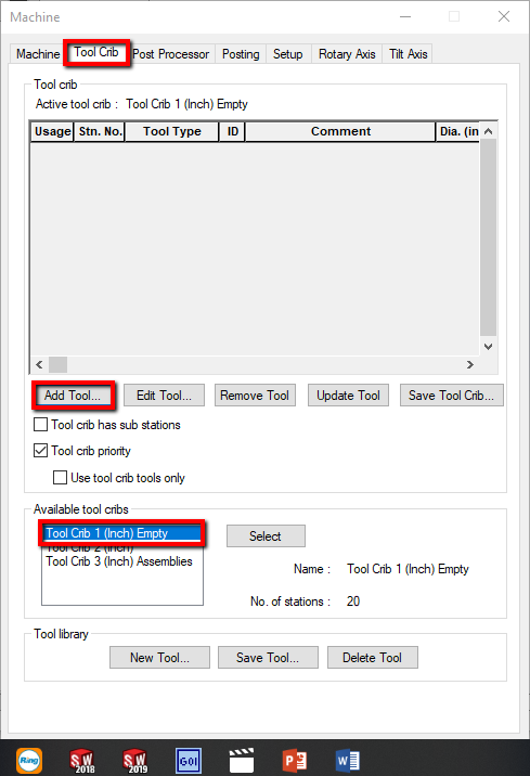
Move on over to the Tool Crib tab. Take a sip of that brew. Get comfortable, because you’re going to be in here a lot for the next little while. The first matter to deal with is to start from an empty Tool Crib. Double click on the default Tool Crib 1 (Inch) Empty. You should see the Active Tool Crib change name at the top. For those of you who get a dialog asking to Prompt or Auto, go back and read the section above the units. Empty files without programs are way easier to start with.
Now that we’ve got all that cleared up, the real business begins. Let’s start adding some tools and run through the process.
![]() Adding Tools:
Adding Tools:
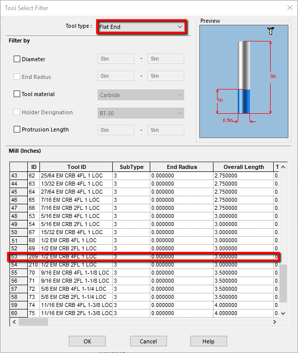
Click Add tool and you’ll be greeted with a dialog allowing to filter down to a specific tool. First thing’s first, choose your tool type from the drop down menu at the top. I’m going to go with Flat End. You may want to filter the results using the other options to narrow the search down. I’d recommend at the very least filtering out the Tool Material at this point, as it’s one of the only items you can’t adjust in the SOLIDWORKS interface. If you don’t see a tool listed of the material you need, you can always copy one of the existing tools in the Technology Database>Mill Tooling>Flat End Mill section, change the material and save it. Just be sure to check the Active checkbox otherwise you’ll be hunting around for a little while.
Who doesn’t love a shortcut? Whilst you’re in the Tool Select Filter dialog, if you hold CTRL or Shift you can select multiple tools to drop in your tool crib in one shot. Though, if you’re planning to modify the tools, you may want to make life simple and just go one by one. Maybe it’s my grey hair, maybe it’s the kids, maybe it’s Maybelline, but I always have a tendency to forget which tool I’ve modified and inevitably save the wrong one.
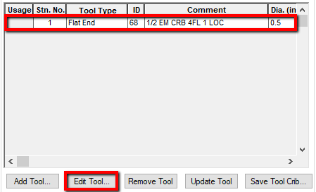
Once you’ve found one, select it and click OK to add it to your tool crib. If you want to make changes, I recommend doing it now, before your mind plays tricks on you, like it seems to for me. Click the tool in the tool crib and hit Edit Tool . Punch in the numbers you need into the relevant section here.
Couple of things to note, whilst the Flute Length isn’t critical to have, it most certainly is useful. If there’s no relief, it’ll help you spot areas where you may rub the shank against stock material during the toolpath simulation. If you’re trying to change your flute length but it won’t take the number, double check the Tool Protrusion on the Holder tab. It won’t allow you to have a flute length that’s longer than the tool protrusion, because, well, you’ll probably have more serious issues if you’re trying to cut using a portion of the flute that’s inside the holder.
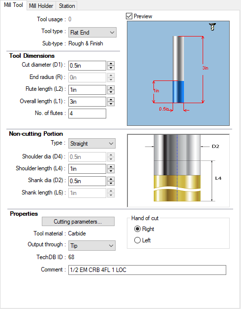
The Hand of Cut is also going to play an important role as it determines your spindle direction. Right hand will trigger a CW spindle rotation and a corresponding M03 (if you’re using a Fanuc-based control). Output through Tip is going to be the default for 99.9% of you but there’s always one, isn’t there? Take a ball nose for example, Output through Center will drive the toolpath generation to be output at the very center of the ball, so the code generated would always be the radius of the tool away from the part.
For those folks who want to drive your tool offsets and/or coolant based on Tool Selection, pay attention. See the Machine>Posting tab for the switches for tool offsets and coolant. You’re going to need a post processor that supports that function. If you want to test your post out, program a part, plug in some numbers that are different to the tool number and set the coolant to something other than flood and post it out. If they come out, you’re in luck, if not, contact us and we can help you out.
If you want to control feeds and speeds based on tool selection, you can adjust them for a particular operation here, but more than likely you’ll want to be doing this in the database. Stay tuned as we’ll look at that later on.
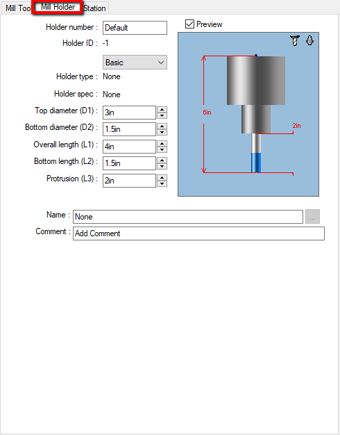
Move on over to the Holder tab. Most of the stuff here is self-explanatory but aside from the aforementioned tool protrusion, the most important thing in here is that you input the correct numbers, particularly if you’re using gouge/holder checking in 3, 4 or 5 axis. In some older 5 axis machines that don’t support Tool Center Point Control, the tool protrusion, and overall length of the holder get added by the software to maintain the correct position. Also, if you’re not the gloating type and underestimate the size of your holder when using the gouge checking, you’re going to see sparks fly. If you want more realistic looking holders, switch the type from Basic to User Defined and check out the following location for some prebuilt holders:
SOLIDWORKS CAM Users: C:ProgramDataSOLIDWORKSSOLIDWORKS CAM 2019ToolingMHolders
CAMWorks Users: C:CAMWorksDataCAMWorks2019x64ToolingMHolders
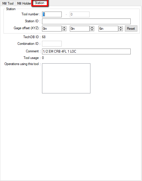
Last but definitely not least, click the Station tab. Unless you’ve got one of those clever new machines that uses characters to call the tool, the most important parameter in the whole tool definition is the Tool Number. After all, it’s what tells the machine which pocket to use, and we need to make sure this is synced up otherwise it’s going to get real interesting, real fast. If certain tools live in your machine and never change location, you can set those locations up now. If it varies from part to part, then you can leave them at the defaults for now, but you’ll have to adjust them as required in each program. They’ll only be adjusted in that program though and will revert to the defaults we set here on every new part.
If you’ve got some crazy machine with two tools at one station and you’re using Sub Stations then you can use the X and Y offsets to shift the position of the tool. Z offset will be automatically calculated from the holder length and tool protrusion but can be adjusted here accordingly.
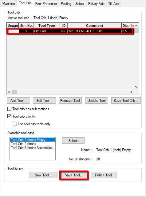
![]() Save Tool:
Save Tool:
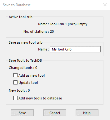
Once you’ve entered your details, click OK . Be sure to select the tool and click Save Tool at the bottom of the Tool Crib window. You should be prompted by a dialog asking you to Add or Change the tool. Without wanting to delve into the structures of a database, this prompt determines whether you want to create a new tool definition or modify the existing one. Given that it’s your first adjustment, I’d recommend using Add so that it creates a new ID in the database for you. Change will modify the existing ID but that could just confuse matters. If you’re a ‘do it once and do it right’ kind of person, well, you’re all set, but for those of us who make ‘corrections’ if you need to make a minor change later, just use the Change option to prevent having multiple entries in the database for the same tool.
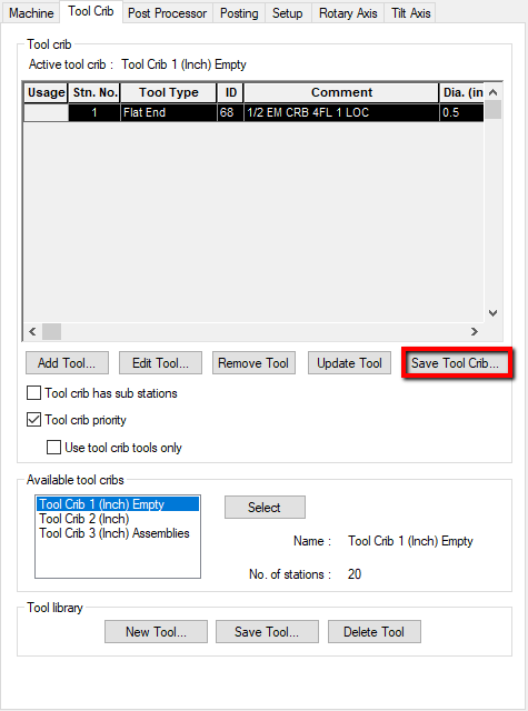
![]() Save Tool Crib:
Save Tool Crib:
At this point it’s just a case of rinse and repeat, ensuring that you save each tool. Saving the tool, however, doesn’t mean that this crib is available in other files. You’re going to have to give it a name by hitting the Save Tool Crib option, to do that. If you’re just updating the crib with some changes, just keep the same name and it’ll overwrite it.
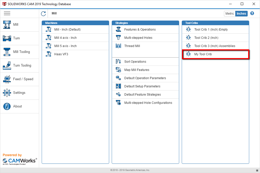
If you’re wanting to tweak feeds and speeds and associate them to tools, you’ll need to go into the database. Don’t worry though, it’s not a difficult process. Fire up the Technology Database , select the Mill option on the left and click on your newly created tool crib from the right.
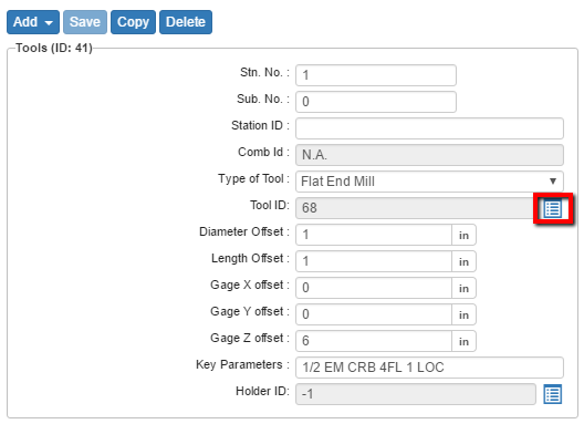
You should see all of the tools listed. Click on a tool and select the box to the right of the Tool ID from the parameters on the right. This takes you to the exact ID in the database that your tool crib is using. Beneath the tool, parameters is what you’ve been waiting for.
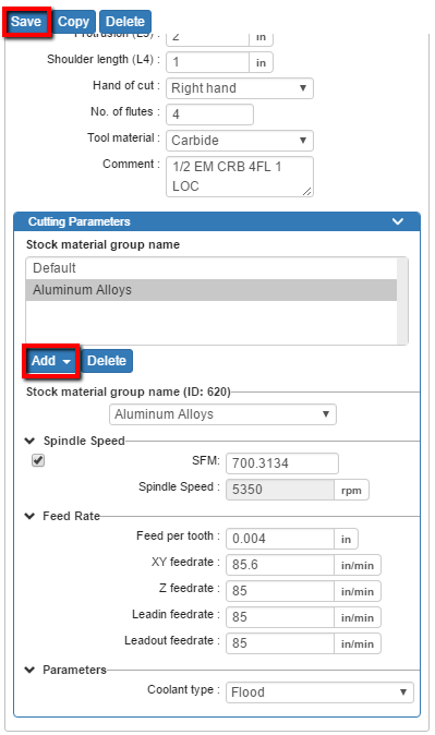
Click Add and select a Material Group to associate. Fill in your specs for each material, hit Save and repeat for your other tools. Just don’t forget to use the Tool option on the F/S tab in the operations.
So there you have it, the ins and outs of customizing tools in your Technology Database in SOLIDWORKS CAM and CAMWorks. Don’t forget to subscribe to our blog and in the words of Looney Tunes, that’s all folks!
Have questions? Please contact us and we will point you in the right direction. Or you can get started with a free trial of SOLIDWORKS CAM. Thanks for reading!