You’ve been through the tutorials, took a class or two and are feeling pretty good about getting programming using SOLIDWORKS CAM. But every time you fire it up, you always repeat the same steps, Machine, Tool Crib, Post Processor etc and every time you think to yourself, there must be an easier way.
There sure is, and you’re in the right spot.
Take a celebratory sip of your favorite brew, stretch those knuckles, as we’re about to walk you through your first steps of getting your machine and post processor setup.
Setting Up Your Machine in the Technology Database
If you’re more of a ¼ mile than a Bonneville type of person, look out for the traffic signals highlighting the key areas to adjust and they’ll get you off the line and into victory lane ASAP.
![]()
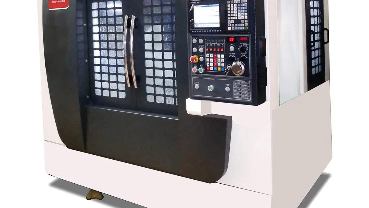
So you fire up your SOLIDWORKS, check on the SOLIDWORKS CAM add-in and we’re ready to go. Flex those Google skills and find out all of the specs of your machine. We’ll use a common example, a Haas VF3.
So we land on the Haas specs page. Now before you start pulling out your credit card and loading it up with optional extras, get your machine specs noted.
Here are some specifications from the datasheet for a Haas VF3 vertical mill.
X Axis Travel: 40 in
Y-Axis Travel: 20 in
Z-Axis Travel: 25 in
Max Rating: 30hp
Taper: CT or BT 40
Max Speed: 8100rpm
Rapids on X,Y,Z: 1000 in/min
Max Cutting: 650 in/min
Tool Changer Type: Carousel or Optional SMTC
Tool Capacity: 20 Tools
Customizing Your Technology Database
We’ll need these to customize your Technology Database. Speaking of which, get that bad boy fired up, it’s time to start dialing things in.
Go to your Tools menu in SOLIDWORKS, slide across over to the SOLIDWORKS CAM menu and click on Technology Database. Click on the Mill-Inch (Default) and hit Copy.
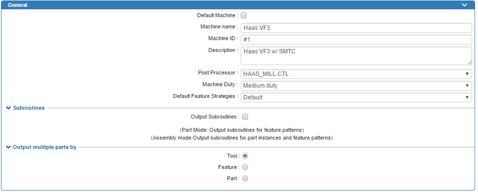
Establishing Your General CAM Settings
![]() Machine Name
Machine Name
For your Machine name, get as creative as you want. But don’t come to me when your better half starts making you do chores when she realizes what loading the ‘Dishwasher’ or ‘Washing Machine’ really means.
Machine ID and Description can be used to make it easier to determine a specific machine. Useful if you’ve not had your coffee fix on that dreary winters day and you can’t remember which machine has the side mount tool changer and which has the carousel.
![]() Post Processor
Post Processor
Quite possibly the most overlooked portion of any CAM system. You wouldn’t go dropping thousands on a race motor and then bolt on some cheap and nasty retreads on, would you?
Do yourself a favor, flex those knuckles and make your way over to our website. Not all posts are made equal.
Download a free post processor for SOLIDWORKS CAM /CAMWorks
Want to reduce setup times by outputting a tool list in the code? Want to preload tools for your side mount tool changer to reduce cycle time?
Don’t see a post processor for your machine? Hit the Get a Custom Post button, fill in your details and we’ll reach out to you to discuss your needs.
Machine Duty
That’s enough of the sales pitch, let’s get back to it and talk Machine Duty . This is arbitrary, but it’ll be used to determine feeds and speeds if you use the Library option.
If you’re a bit green, set it more towards the Light Duty and it’ll run slower feeds and speeds.
If you’re the type that likes to “get ‘er done” and create chuck key type holes in the wall, then you’ll probably want to go for heavier duty.
Default Feature Strategies
If you’re in SOLIDWORKS 2019, the next option you’ll see is an option for Default Feature Strategies .
If your shop looks like Santa stopped by every type of machine tool dealer before making his way down your chimney, you’ll probably want to check out the following link to see how you can tie your machining parameters to your mill, plasma, waterjet, laser, and router.
See What’s New in CAMWorks 2023
Output Sub Routines
If your CNC mill makes a Commodore 64 look like a powerhouse or you simply want to cut down on program load times, you can enable the Subroutines option to output M97 or M98 style subprograms.
If you’re new to g-code though, prevent hair loss from excessive head scratching and leave this unchecked.
Output Multiple Parts by Tool
So you took an order for a large batch of parts and you want to cut down runtime. Go Big or Go Home, right? After all, home is just the other side of the garage door.
If you set the Output Multiple Parts to Tool, it’ll machine all the features using the same tool on the same part first then repeat the same on the next part.
Set to Feature , it’ll machine a feature, such as a pocket, before moving onto the next feature. Part is going to allow you to machine an entire part to completion, often used with routers when you pull the part off the table, dust it off and get it ready for any second op work.
Adding Specifications
Take another sip of that brew and stretch those fingers, as we’re about to start punching numbers.
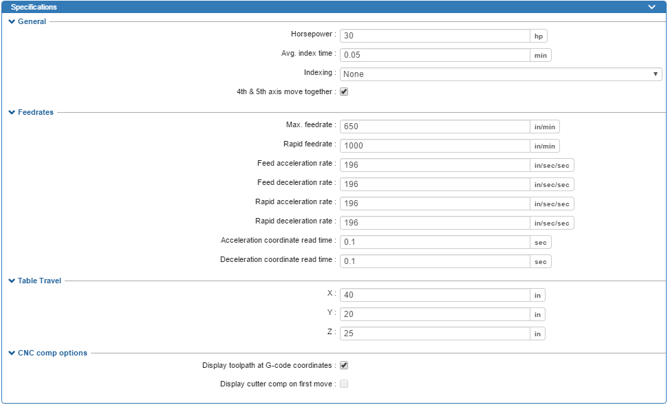
Horsepower
Time to break out your best Tim ‘the tool man’ Taylor style grunt here. Enter your max rating from your machine specs.
Or don’t. Entirely up to you here, it’s only used for reference but may help you identify a specific machine (if you’re allowed to buy more).
Average Index Time
Time to break out that stopwatch… let’s be honest it’s more likely your phone. This is how long it takes to get from one setup direction to the next.
So in a single setup part, you’ll see it added once whereas, in a 4 or 5 axis program, you’ll see a total based on the number of setups. This will affect your cycle time estimates and you’ll see this added to the non-cutting portion time in the Statistics tabs.
More accuracy here equals more accurate quotes.
Indexing
Before you start spending hours digging through your crawlspace/attic, your Rolodex can stay where it is. This option controls the default setting for your machine.
If you’re new to programming, leave this set to None unless all you do is 4 or 5 axis programming. Didn’t your mother or father used to say you’ve got to walk before you can run?
4th and 5th Axis Move Together
Is your machine capable of rotating and tilting in unison to execute the perfect g-code tango or does it look more like an embarrassing uncle who wants to show off his best robot impression?
When the 4th and 5th axis moves together, it will use the longest movement of the two rotations as the time estimate otherwise it’s just going to sum both movements.
![]() Max Feedrate
Max Feedrate
The fastest cutting speed your machine is capable of. SOLIDWORKS CAM won’t allow you to enter a number higher than this value, and for those SOLIDWORKS CAM Professional users who like to use Volumill, this will control your high feedrate traverses.
Rapid Feedrate
I know what you’re thinking…rapid moves don’t have feedrates called out so what’s the point here?! Cycle time estimates. Using the move distance and the rapid rate, we can estimate how long the machine is spent rapiding.
Feed Acceleration/Deceleration Rate, Rapid Acceleration/Deceleration Rate
Purely for cycle time estimation, if you’re looking to accurately calculate how long it takes to get from one feed rate or rapid rate to the different one.
Accel/Decel Coor Read Time
Purely for cycle time estimation and mainly a consideration with older machines that take some time to register when they are at the correct feedrate.
Table Travel
Punch the numbers from your research in here. Used for reference only but might be useful to have to avoid taking windows out of your machine, or worse yet, having to cut holes in your drywall to run a job.
Display Toolpath G-code Coordinates
This ones’ on you. When you’re setting up your tools, do you enter the wear amount into the compensation/offset pages or the diameter/radius?
The standard database is set up to automatically compensate for nominal tool diameter, and as such would use a wear amount for the comp numbers in the control.
If you want to use the radius/diameter values in your control for the offsets, you’ll need to customize your database to have your Contour Mill operations set to Without Compensation in the NC tab. This option will control whether the toolpath is displayed as the compensated path or the non-compensated path when you’re using the CNC Compensation set to On .
If you’re in any doubt, leave it turned on.
Getting Your Turret Settings Right
Onto the Turret section, this is where we can dial in our machining time estimates, so, you know, you can quote more accurately. Much better than using something based on how quickly the proverbial fall off a shovel or how many digits/knuckles are remaining this week. So let’s get to it… time is money.
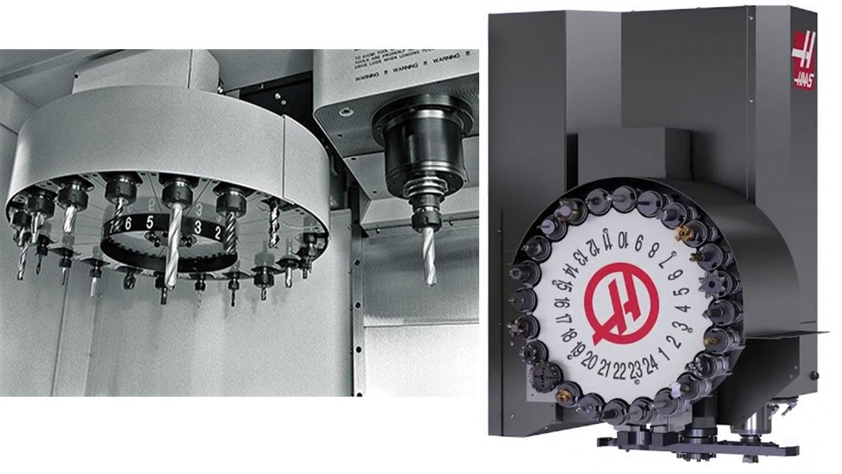
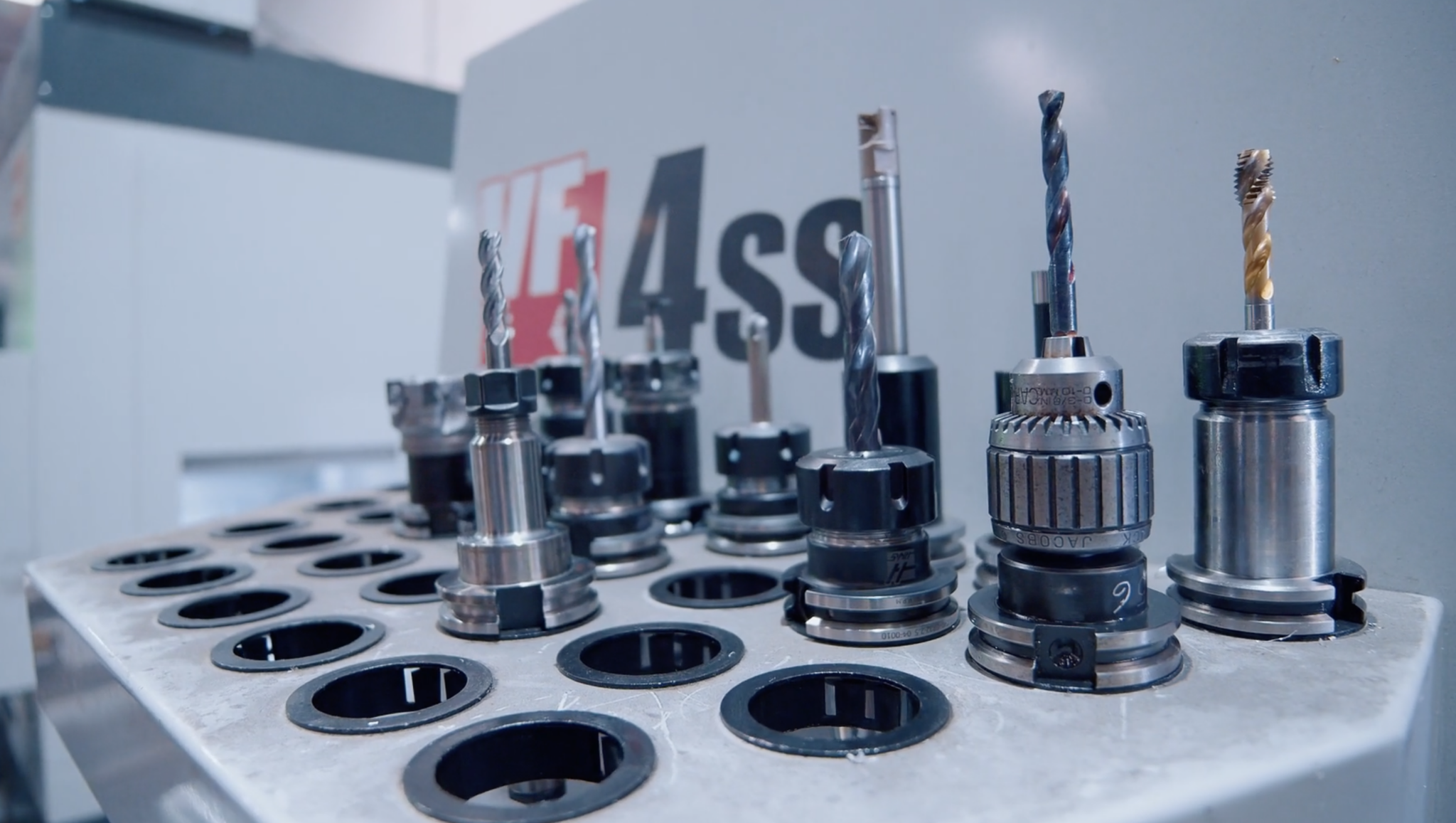
On the left, a carousel style Sequential tool changer, on the right, a Side Mount Tool Changer with the arm that is capable of pre-loading tools, saving cycle time.
Changer Method
This setting is important if you want accurate cycle times. Using the Turret Indexer method won’t add any additional time for tool changes, so the only added time on top of toolpath time is the Average index time which is factored in once per setup.
Using either the Sequential and Pre-load Tool Changer methods will both factor in tool change times. The time added will be a combination of the tool change swap time and any additional seconds based on the number of stations skipped (defined in the table in the Tool Changer Times).
But we’ll get to that shortly.
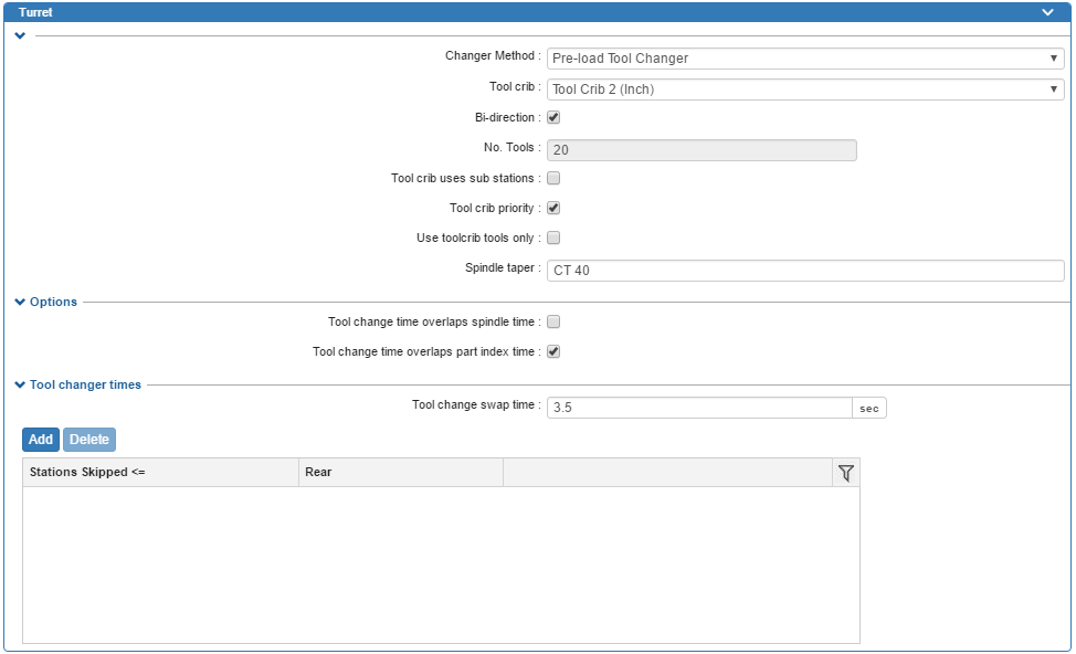
![]() Tool Crib
Tool Crib
The set of tools that you want to be associated with this machine… need we say more? If you want to learn how to build a tool crib, check out my other blogs:
Bi-Direction
Does your tool changer rotate both directions or does it look more like a learner driver stuck on a roundabout?
This will directly affect your tool change times. If you have a total of 20 stations in your machine and you’ve got bi-direction checked, you can reach all tools within 10 stations.
If it’s unchecked it may have to rotate up to 20 times to get to the next tool and your tool change time is going to match.
No. Tools
No explanation necessary for what needs to be entered here. But one thing to note is that If you are using the Bi-Direction checkbox above, then this is how it knows for example that T20 is next to T1 in your changer so it will only add the time to move one place rather than twenty.
Tool Crib Uses Sub Stations
This is used for machines where you may have 2 tools located at one station. A simple example would be a lathe turret where you may have an OD tool and a boring bar at the same location but using different offsets. If you’re using a mill, you can forget this option unless you’ve got a pretty special tooling setup.
![]() Tool Crib Priority
Tool Crib Priority
So you’ve dropped a whole bunch of cash on some decent tools, you want to use them, right?
This will depend on the strategies you’re using as to how successful this will be. If your strategies are set to use a particular tool, then this setting won’t affect that.
But if you’ve got it set up to use any ½” flat end mill for example then this setting will force it to look in your tool crib to find an appropriate tool, before adding one from the database.
Use Tool Crib Tools Only
Sounds like something you want to be enabled, doesn’t it? After all, why would you want it to use tools that you don’t have?! Well before you get all click-happy, it’s probably good to explain the outcomes.
Let’s use an example, say you want to drill a hole but you didn’t want to go adding every drill size under the sun into your tool crib.
Since you didn’t add all your drills to the tool crib, it won’t generate that particular operation, so you’ll have to manually add that operation, define the parameters and select the tool.
If you left this option unchecked, it would create the operation, but the tool may or may not be the one you want to use.
Worst case is you’ll have to change the tool, far less work than adding operations, setting parameters and selecting the right tool. Worth thinking twice on this one.
Spindle Taper
Another one of those things that are for reference only, so if you don’t know, it’s not going to ruin your night. In the case of the Haas, it’s either CT or BT 40.
Tool Change Time overlaps Spindle Time
For most mills, this won’t be possible, since your tool will be stationary during the tool change. A simple example would be a lathe, as the main spindle can be turning and accelerating/decelerating whilst the turret indexes.
Tool Change Time overlaps Part Index Time
Simply put, this tells it whether a tool change can occur whilst the part is rotating to a new position when using a 4 or 5 axis machine.
Tool Change Swap Time
If you’re the type that’s skim reading this, and you just so happen to stumble onto this section, then I suspect you might just want to plug in an average time it takes to go from chip to chip or from the moment the tool is in the home position to the new tool is loaded and ready to go.
But if you’re the type that likes to correct people’s spelling and punctuation without being asked, or hangs pictures using a level (let’s be honest if you’re actually reading this properly, I’d near enough guarantee it) then you’ll want to be spending some time in this area.
The time can be broken down into a couple of distinct stages. The first being the time taken to rotate the changer to the next tool which causes the greatest variance on the tool change time. The second stage is the actual changeover of the tool.
The time taken to get from one station to another station can be defined in the table. The Stations Skipped column controls the number of stations between the tools (forwards or backward if your machine is bi-directional) whilst the Rear column denotes the time in seconds to make the rotation.
The Tool Change Swap Time would then be the time it takes to load the tool only. For an arm style changer, the swap time would be to remove the tool from the changer and the spindle and to switch them. For a carousel style changer, it would be the time unloading one tool from the spindle plus the time to insert the next tool.
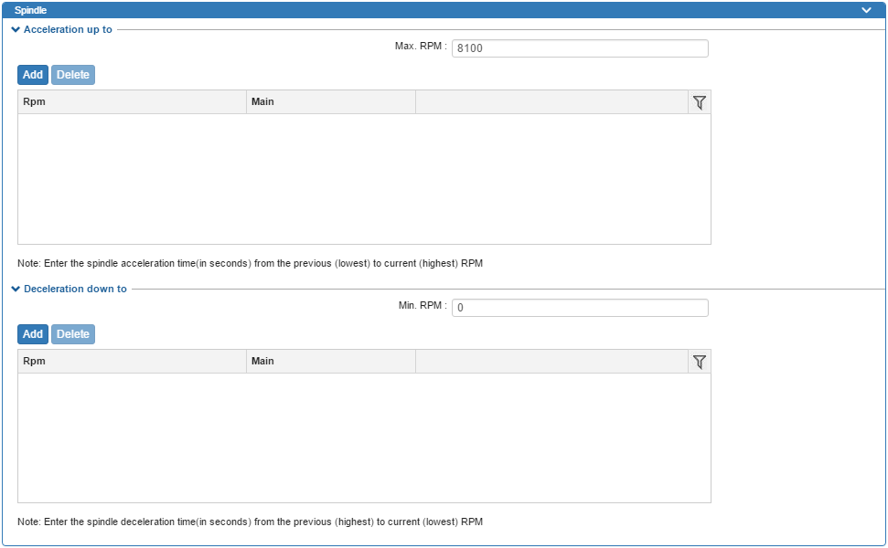
![]() Max RPM:
Max RPM:
Self-explanatory with this one. Either set it to your machine’s maximum or use it as a restrictor to cap your programming always to a maximum RPM value of your choice. For lathes, this will be spindle RPM cap (G50) amount used to limit the max spindle speed when approaching the center of a part in Constant Surface Feed mode.
Min RPM
For a mill, I’d suggest leaving it at 0. For a lathe, however, this will be the minimum RPM used when you’re using Constant Surface Feed mode, this will be the minimum RPM it will use when you’re at furthest away from the centerline.
You might be wondering what the two tables are for? No? Well, you can just skip this bit. They allow you to specify the time taken to accelerate or decelerate between two rpms, because even the Starship Enterprise needs some amount of time to get to warp factor 9.
The end is in sight, I promise. For those of you running up to 3 axis, it is in fact super close. Make sure the Indexing is set to None and you’re good to go, just be sure to hit Save before closing the database otherwise you’ll be reading and writing this all over again!
For those of you using 4 or 5 axis, however, we’ve got a little more to go.
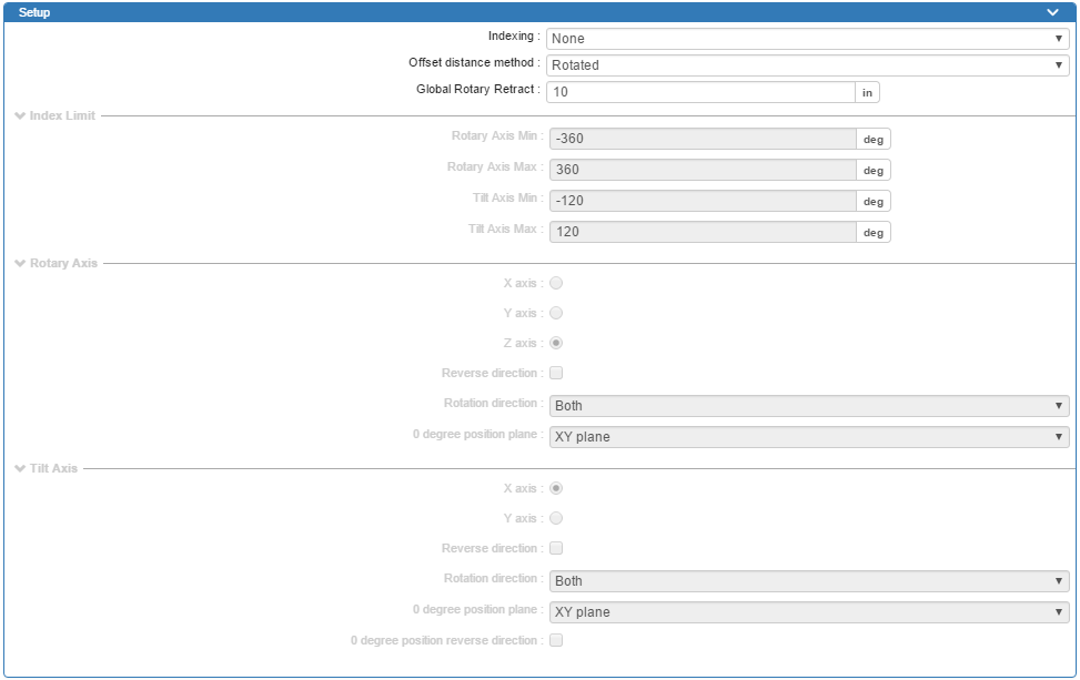
Indexing
Yes, there are two indexing menus, you’ve seen this before, it’s not your memory playing tricks. The one above defines the default setting for this menu whereas this one allows you to plug in the exact details of your machine for when you do want to use it.
This setting will allow you to use the same post processor to switch between 3 axis (XYZ) and 4 axis (XYZ + 1 rotary axis) or 5 axis (XYZ + 2 rotary axes).
Offset Distance Method
Everyone loves a good fixture, even more so when you can drop in a bunch of parts, set one offset and watch it rotate your 4 th or 5 th axis. This setting controls how the linear axes are transformed when you rotate between setups. If in doubt, leave it at Rotated.
Global Rotary Retract
So your 4 or 5 axis is running great but you had a glute-clenching moment when during a reposition, you got a little close to the fixture.
All’s well that end’s well as they say, but this is the number you need to be looking at. This will control the retract when indexing in 4 or 5 axis. Note that the value will be in relation to the work offset from the setup prior to rotation. This will usually be seen when you rotate between setups when no tool change is occurring.
You may see a Z value coming out in your code at this number, or your post processor may be configured to go to Z home during this move for safety’s sake.
Index Limits
Flex those Google skills and set your machine rotation limits using these options. If you’ve got a 5 axis machine and don’t want your trunnion tilting to the ‘dark side’ (ie towards the back of the machine, out of sight of the operator), you’ll want to change these limits to suit.
If your trunnion swings from -90deg to +90deg and the dark side is when at -90, I’d suggest a limit of -5 or -10 degrees, just enough to allow anything around 0 to be permitted.
Rotary and Tilt Axes
Fairly self-explanatory with these, but there are a few things to note about these options. Always use a coordinate system when using 4 or 5 axis and don’t be tempted to use the entity select option that you get in the interface.
You’ll have to use the coordinate system to be able to select the XYZ axes. Also, be sure to check the axis rotation directions are correct unless you like having all of your parts machined as mirror images.
If you’re not sure, program a cube with unique features on 3 of the sides such as a star, a rectangle and a circle. Load the machine without any fixtures/vises/stock material and watch the machine movements to see if the geometry would be machined correctly.
If not, try checking the Reverse Direction for the Rotary and repeat and if not repeat by adjusting the Tilt axes. If you want to limit the angles but don’t want to mess with the machine limits, you can always adjust the Rotation Directions for the Tilt axis to CW or CCW and this will stop the tilting to the ‘dark side.’ For 0 degree position, this is going to set where your rotary and tilt axis zero positions are.
If you’re in any doubt, use the XY plane as a starting point and test runs a simple part like the one mentioned above.
![]() Save
Save
Once you’ve made your changes, don’t forget to hit Save at the top, otherwise, you’ll be needing another brew! And that’s it, you’ve successfully set up your machine in the database.
If your better half can look past the smell, noise and the fact you’re never in the house (perhaps that’s a bonus point), and allows you to spend your second kid’s college fund on another machine, it’s just rinsed and repeat of the above process.
Have questions? Please contact us and we will point you in the right direction. Or you can get started with a free trial of SOLIDWORKS CAM. Thanks for reading!