
When creating sketches or designing parts in SOLIDWORKS, you can often fully detail contours you need with basic sketch entities such as lines, arcs, and points. You can add combinations of these basic sketch entities using familiar tools like the rectangle, polygon, and slot tools, among many others. When more organic shapes and curves are necessary, you also have access to the ellipse and spline tools. Using these tools, you can create complex part geometry efficiently, often with just a few clicks.
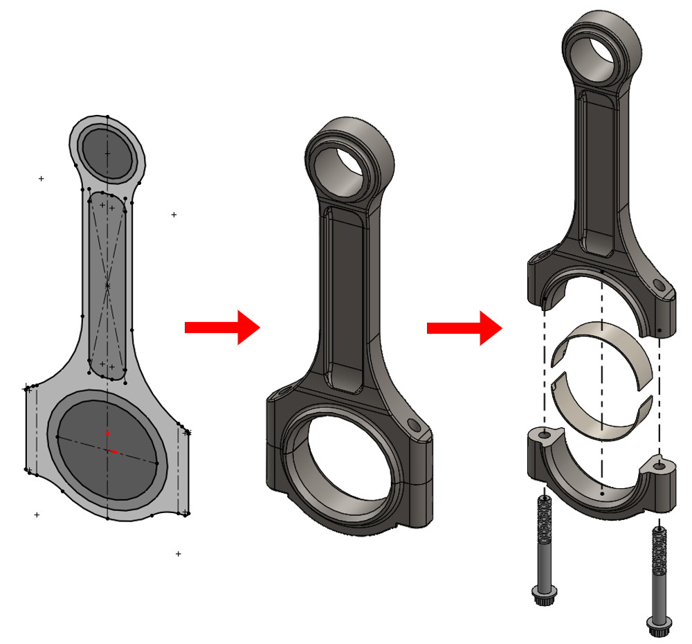
But what if you need to create a specific type of curve that may be best described by a mathematical relationship that standard sketch tools just can’t handle?
Creating Curves Defined by Mathematics
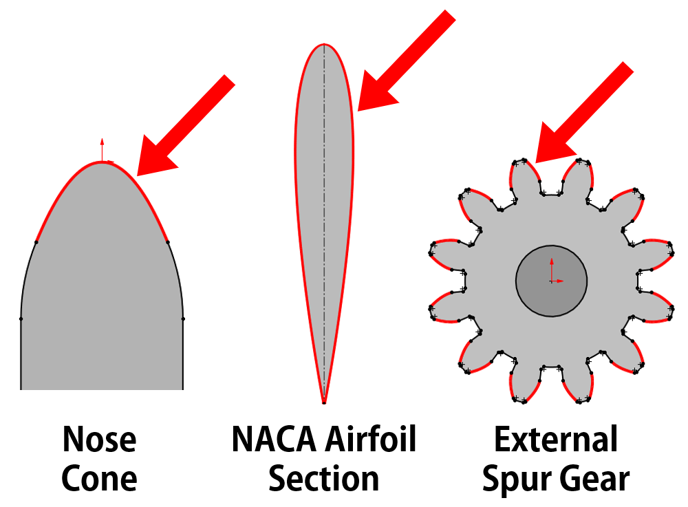
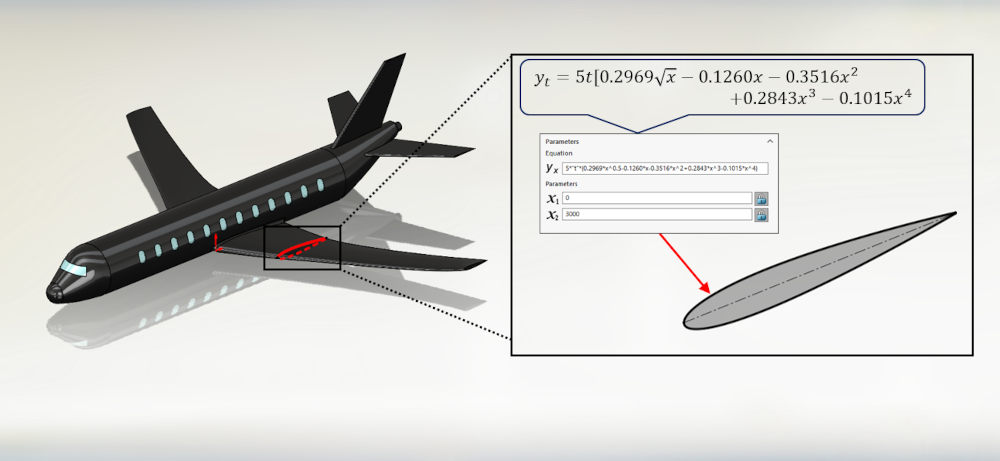
It’s not hard to find parts in our everyday lives whose shape or form has been designed using mathematical equations. Items such as a NACA airfoil profile for an aircraft wing, the nose cone for a launch vehicle, or the tooth profile of external spur gears, all use equations to define their shape. Thankfully, when we need to design a profile that adheres to a specific equation, SOLIDWORKS has a solution for us with the “Equation Driven Curve” tool.
Introducing the Equation Driven Curve Tool in SOLIDWORKS
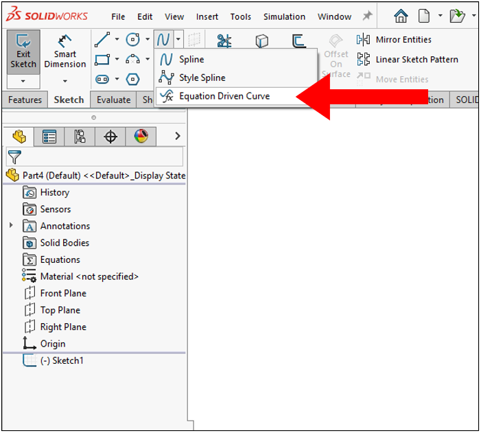
Equation driven curves are exactly what they sound like: a curve in a sketch whose path and curvature are defined by an equation. This allows us to enter specific mathematical expressions to drive the form of our contours and, ultimately, our designs. The “Equation Driven Curve” tool is found under the spline drop-down in the “Sketch” tab of the command manager.
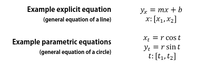
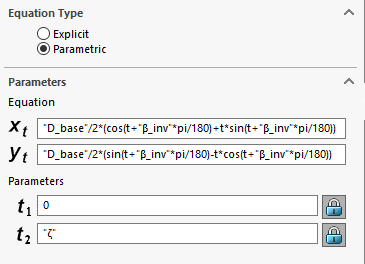
The “Equation Driven Curve” tool has two options for generating a curve: explicit and parametric. Each option gives us a different way to define the curve we are trying to generate.
- Explicit – the curve is defined by an explicit equation with an independent variable, “x”, and a dependent variable, “yx”
- Parametric – the curve is defined by a set of parametric equations, “xt” and “yt”, which define the horizontal and vertical coordinates of each point along the curve, respectively, given an independent variable, “t”
In either case, we enter a mathematical expression(s) along with start and end parameters, such as the general examples given below, which will define our curve in SOLIDWORKS.
How the Equation Driven Curve Tool in SOLIDWORKS is Used
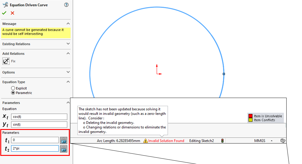
It’s important to note that when SOLIDWORKS creates an equation driven curve, it’s generating a best fit spline. In doing so, SOLIDWORKS does not solve our equations analytically, but instead resolves them numerically. As a consequence, SOLIDWORKS cannot solve equations that create curves which self-intersect, have coincident endpoints, or have discontinuities.
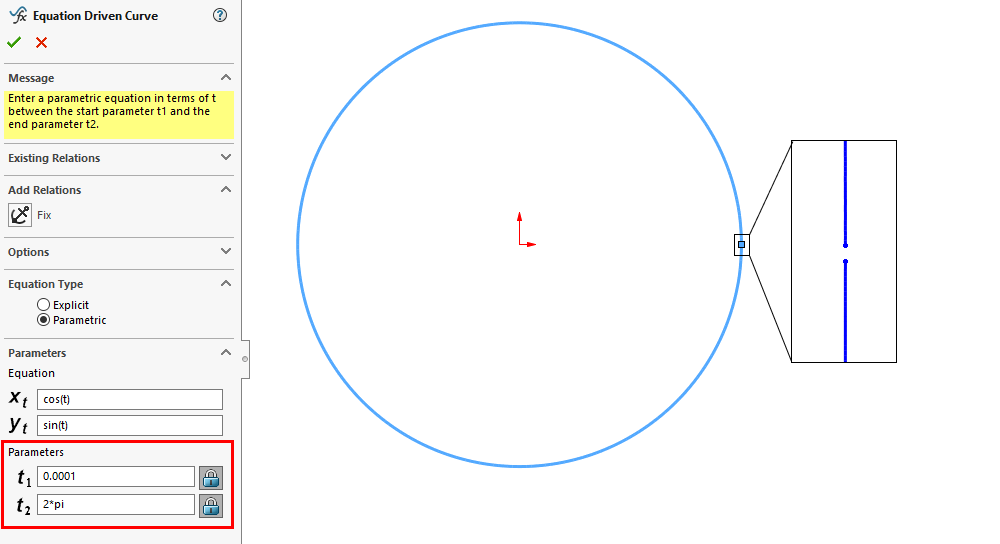
For example, if we plug in the set of parametric equations defining a circle, we must be careful with our parameters. We cannot plot the full circle from 0 to 2π with the “Equation Driven Curve” tool because the spline it generates would have coincident endpoints. In this case, we must choose values such as 0.0001 to 2π so that SOLIDWORKS can find a valid solution. Alternatively, we could instead create two equation driven curves each representing one half of the full circle. When using explicit expressions, it is not possible to create a curve that self-intersects or that shares endpoints, but it is possible to have discontinuities (e.g., the tangent function), so we need to be careful here as well.
Which Option Should I Use When Creating Equation Driven Curves in SOLDWORKS: Explicit or Parametric?
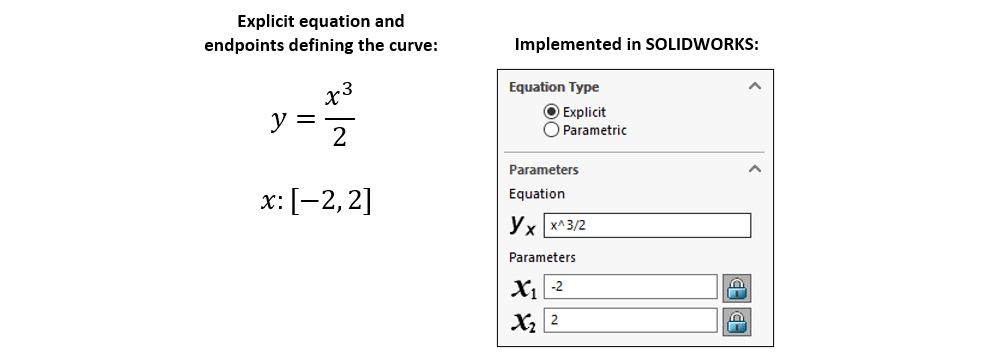
Whether we select explicit or parametric depends on the curve we are trying to generate. It really just comes down to this question: Is the curve more easily represented explicitly or parametrically? In some cases, the curve can be represented either way. A good example of this is a basic polynomial curve such as cubic curve.
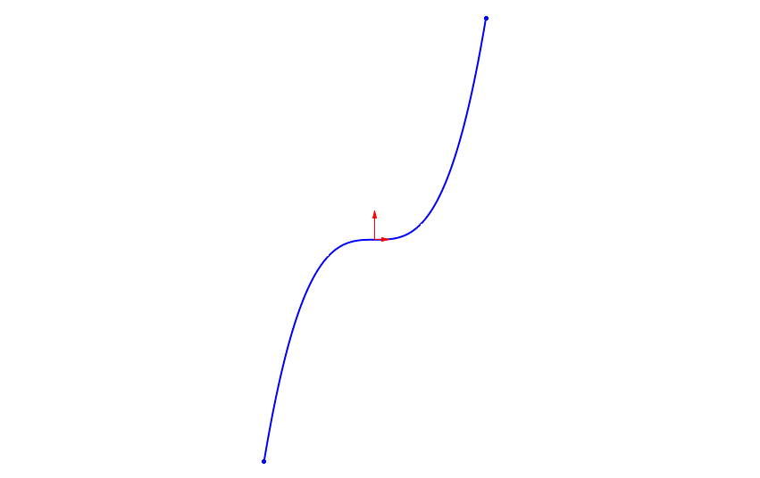
Using the “Explicit” option to generate the example cubic curve shown above with a simple explicit expression in SOLIDWORKS:
We can also generate the same curve using the “Parametric” option with an equally simple set of parametric expressions in SOLIDWORKS:
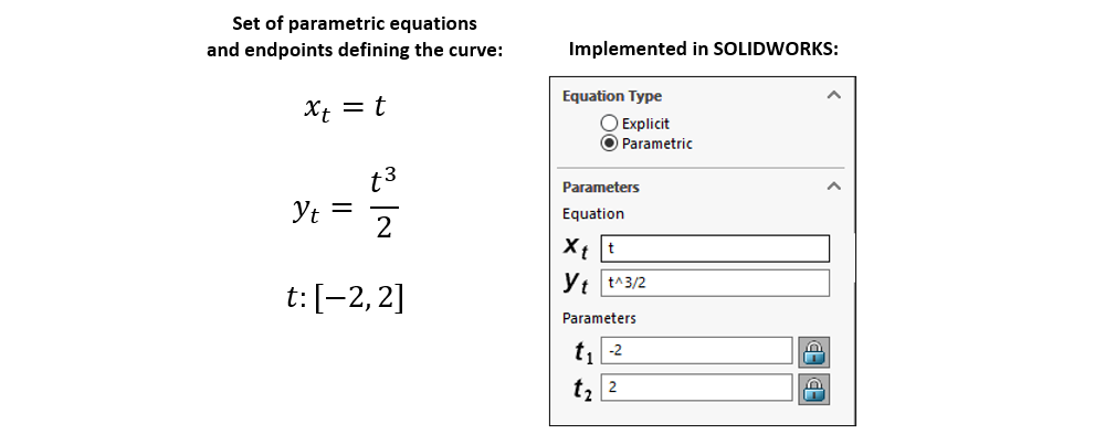
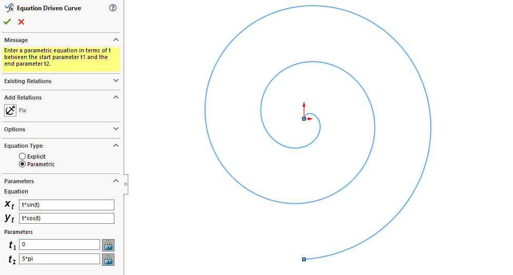
In this case, the expressions needed to generate the curve are trivial regardless of whether we want to use the explicit or parametric option. But this is not the case for all curves. Therefore, we must evaluate the geometry we are trying to create in our models and consider which option is the best fit. For example, we can easily represent a spiral parametrically in SOLIDWORKS, but representing it explicitly would be overly complicated and would require multiple piecewise curves.
How-To Fully Define an Equation Driven Curve in SOLIDWORKS
After generating an equation driven curve, you may notice that it is under defined. Although we have generated the curve with a specific expression and range of values, SOLIDWORKS allows the curve to be moved and/or rotated. This gives us greater flexibility when positioning our curve. For example, it’s easy to create a regular parabola using the explicit expression “y = x²”, as shown below.
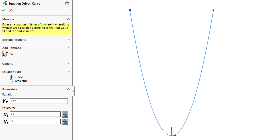
But what if we want that parabola to lie at some other angle instead of straight up and down? Thanks to the flexibility SOLIDWORKS gives us, we can add relations and dimensions to control the orientation of our equation driven curve as we would with regular sketch entities. With the correct relations, we can even simply click and drag the curve to the appropriate orientation.
While this added flexibility can be useful in certain situations, adding dimensions, relations, or clicking and dragging our curve can sometimes result in unexpected behavior. As we manipulate an equation driven curve, SOLIDWORKS is doing work behind the scenes to make sure the curve still fits the expressions we used to define it. This means that the solutions SOLIDWORKS finds as we manipulate the curve don’t always give us the results we are looking for. With that in mind, it’s typically useful to define the position and orientation of our equation driven curves using the equation(s) themselves, when possible.
Once our curve is generated, we can simply add a “Fixed” relation to the curve and its endpoints to fully define it within our sketch. We can also “lock” the endpoints of the curve by clicking the lock icon next to the parameter input boxes, but keep in mind that this only locks the start and end values for the generation of the curve itself.
Equation Syntax, Symbols, and Functions in SOLIDWORKS
Much like using equations elsewhere in SOLIDWORKS, when using the “Equation Driven Curve” tool, we must use correct syntax and operators. The syntax and operators can be different than what we are used to writing by hand, so it’s important that we enter our equations correctly (SOLIDWORKS will show invalid equations in red text). Below is a quick reference for operators, syntax, order of operations, and functions available to us when using the “Equation Driven Curve” tool.
| Operation | Operator |
| Addition | + |
| Subtraction | – |
| Multiplication | * |
| Division | / |
| Exponent | ^ |
Functions
| Name | Function | Notes |
| Sine | sin(x) | “x” in radians, by default |
| Cosine | cos(x) | |
| Tangent | tan(x) | |
| Secant | sec(x) | |
| Cosecant | cosec(x) | |
| Cotangent | cotan(x) | |
| Inverse sine | arcsin(x) | Returns value in radians, by default |
| Inverse cosine | arccos(x) | |
| Inverse tangent | atn(x) | |
| Inverse secant | arcsec(x) | |
| Inverse cosecant | arccosec(x) | |
| Inverse cotangent | arccotan(x) | |
| Exponential | exp(x) | Base “e” (Euler’s number) raised to the power of “x” |
| Logarithmic | log(x) | Natural log of “x” (base “e”) |
| Square root | sqr(x) | Equivalent to “x^0.5” |
Note: The functions “int()”, and “sgn()” are also valid for use, but don’t have practical application when used in the “Equation Driven Curve” tool and are therefore excluded from the table.
Additional Syntax and Constants
| Name | Symbol(s) | Notes |
| Parenthesis | ( ) | Used to group symbols to control order of operations |
| Pi | pi | Ratio of the circumference of a circle to its diameter (π) |
SOLIDWORKS equation syntax requires that operators are used between every individual number, symbol, or variable. For example, while we can write “y = rsinx” if we were jotting it down on a piece of paper, in SOLIDWORKS we would need to enter “y = r∗sin(x)” for the syntax to be correct. SOLIDWORKS also follows the same order of operations we are all used to in regular mathematics (e.g., “y = 8∗(1+x)” is not equivalent to “y = 8∗1+x”). We can also use dimension names and global variables to help define and control our equation driven curves.
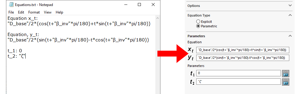
As a personal tip, I often prefer writing out my equations in a text editor (such as Notepad) if they are significantly lengthy or complex before entering them in SOLIDWORKS. I find that this makes reviewing or editing our equations as we are not limited to the relatively small input box given to us in the Property Manager for the “Equation Driven Curve” tool. At that point all we need is a simple copy and paste and we are good to go!
Hopefully, this post has given you a good idea of what the “Equation Driven Curve” tool can do and how you can apply it to your own designs. If your application requires features or parts whose form is driven by a mathematical expression, then this tool is for you!
As always, if you have any questions, be sure to reach out to us! Contact us at Hawk Ridge Systems to discuss how the suite of SOLIDWORKS software can help improve your workflows and products.