A quick release pin is used in many designs to keep the holes of multiple components aligned. They are commonly used when assembly and disassembly are frequent and needs to be done quickly. Some common uses are vehicle hitches, adjustable scaffolding, telescoping arms, or basically anything with holes that need a pin to align it. Traditionally, quick release pins are made up of multiple components and are spring-loaded, have a cotter pin, or a swinging wire to keep them in place.
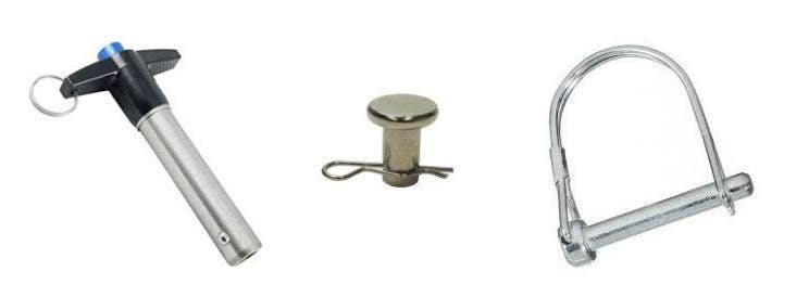
Examples of traditional quick release pins.
Creating a Compliant Mechanism
I have chosen to design a compliant mechanism that will act as a quick release pin. A compliant mechanism uses the elasticity of the material to perform a mechanical function. In the case of the locking pin, instead of using a ball and spring, or swinging wire, the compliant mechanism will be elastically deformed when entering the hole and then return to its original shape once it passes through. Kind of like a snap-fit. The compliant mechanism will be one component instead of multiple components needing assembly. This makes it ideal for the 3D printing process. You can see the compliant mechanism in action below.
The right view of the compliant mechanism elastically deforming to fit through a hole and then returning to its original shape to lock the pin in place (run in SOLIDWORKS Simulation).
Utilizing 3D Printing for the Manufacturing Process
Since I want this mechanism to be one single part, I chose 3D printing as my manufacturing method. This will allow the design to have complex internal details without having to worry about traditional manufacturing limitations like draft, undercut, assembly, thickness, shrinkage, and probably some other impediments.
I have chosen to use multi jet fusion (MJF) 3D printing through A3D Manufacturing for its material properties, high resolution, and simple design criteria. The MJF is a powder-based printer, so there is no need for me to worry about supports, but I need to make sure that there is a way to evacuate the powder after fusion and cooling. This powder-based printing method also gives me near isotropic material properties so I do not have to be concerned with printing alignment for strength. The high resolution of the printer will also let me get down to 80-micrometer details, which gives so much room to work and design.
This machine is by far the easiest manufacturing process to design for because I only have four design criteria to meet:
- Keep the design small enough to stay within the print bed (15” X11.2” X15”) (380mm X284mm X 380mm)
- For assemblies printed together, maintain a clearance of 0.5mm
- Ensure there are no internal cavities that will trap powder
- No features with details smaller than 80 microns
I would barely consider these as limitations, which is why I chose the MJF for my manufacturing process.
Modeling Using SOLIDWORKS
This model is very simple. It consists of a few revolves, thin boss extrudes and a lot of cuts and fillets. I am going to focus on a few areas of the design where I used some more niche tools to enforce the manufacturing constraints and blend rough transitions.
Global Variable for Clearances
Since I had to ensure a 0.5 mm clearance between the parts that are printed assembled, I created a global variable which I could then reference for my parametric dimensions in my sketches and features. You can create a global variable directly inside the dimension modify box or in the equation manager. Inside of the dimension modify box you can press the equals key (=) and that will make the current dimension a function. If you begin typing characters, a globe icon will appear and clicking it will create a global variable and set the dimension you are editing as that global variable. You can see this process below.
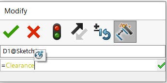
Dimension modify box where a global variable “clearance” is being created.
Creating a global variable links all the clearance values together and ensures they are the same. A global variable also gives me the power to change all the clearances in a single operation if I want to change the manufacturing process or use a different printer.
Indent
The indent command is a great way to force a clearance between two bodies in a part file. During this design, I had an overlap of the inner body and the outer body as seen below. This is a perfect use case for the indent command.
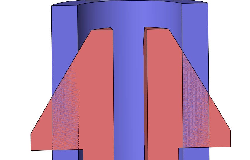
Section view displaying the interference of the two bodies before the intersect command.
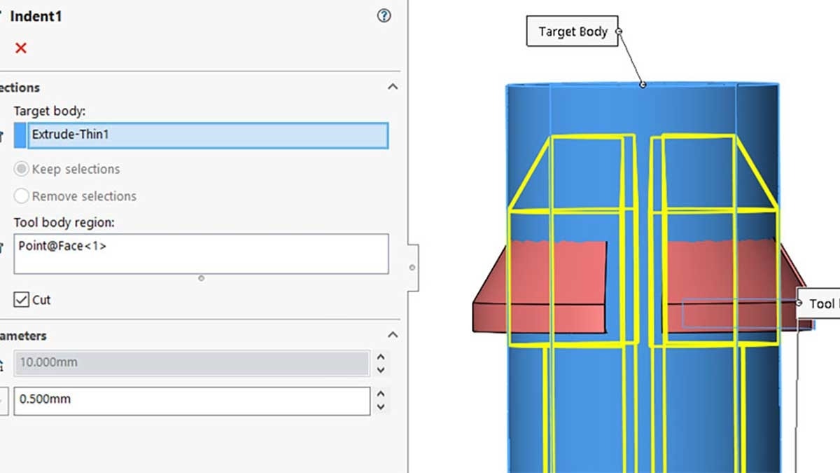
The indent command will take a target body, the blue cylinder, and cut it using a tool body, the red internal piece. You can add a clearance value, and even link it to a global variable. You can see the property manager and preview of the tool below. In order to make the clearance value a function of the global variable, you have to access the modify box of the dimension after the feature has been created.
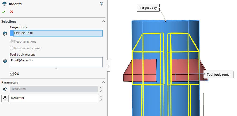
Property manager of the “indent” command showing the yellow preview of the 0.5 mm clearance to be cut.
Clearance Verification
To verify the clearance you have to be in the SOLIDWORKS assembly environment. It was very easy to create an assembly from my multibody part by using the Save Bodies command. The Save Bodies command creates a separate part file for each body in the original part file and an assembly with the components located in the same place relative to the origin. The tool creates a feature inside of the original multibody part file so if any design changes are made they will propagate to the subsequent part and assembly files.
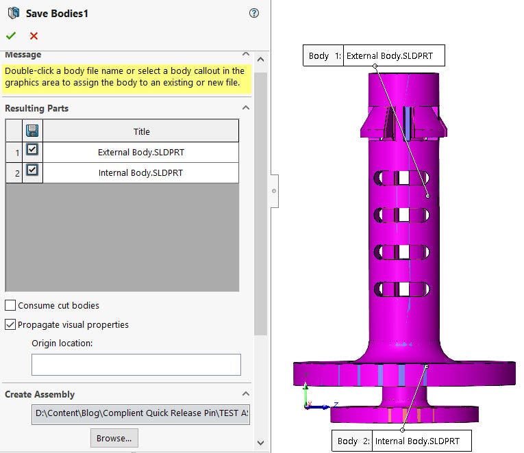
Property manager of the “save bodies” command, which is used to create an assembly file from a multibody part file.
Once the assembly was created it was as simple as using the clearance verification tool between the two parts. Setting the Clearance Value to 0.5 mm the tool checks for any clearances between the parts that are less than or equal to that defined Clearance Value. The image below shows the minimum clearance of 0.5 mm so the model will be safe to print in the assembled position without fear of the components binding.
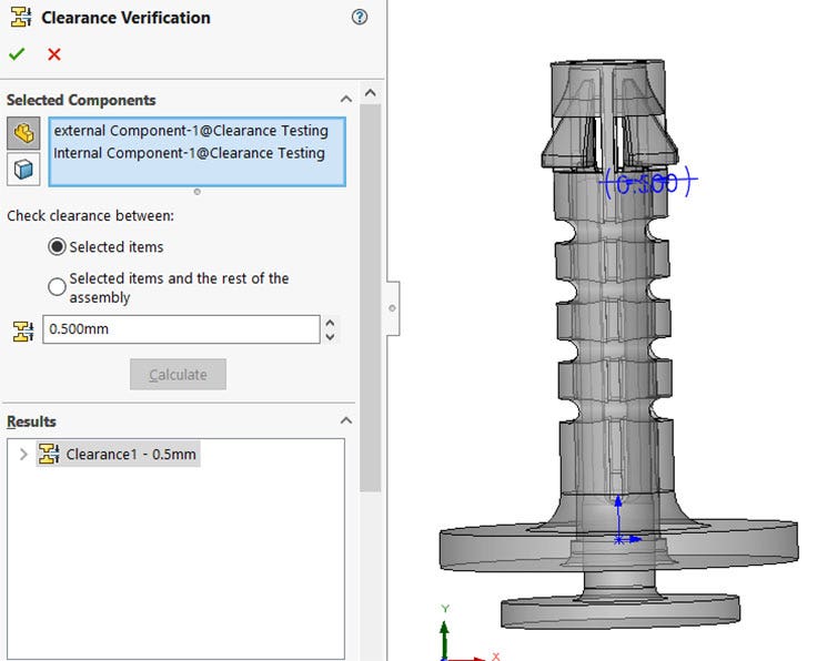
The “clearance verification” property manager confirming that the minimum clearance in the part is 0.5 mm.
Surfacing Blend
After running a dynamic non-linear simulation I found the tab of the red piece was too wide for the channel when it contracted radially. So, to create some more clearance I lopped off 10 degrees of the tab but was left with a little plateau as seen below. My first attempt to remove the unintended geometry was to fillet the undesired faces away but I could not get that to work. I then decided to use some basic surfacing techniques to blend a better transition between the neck and tab.
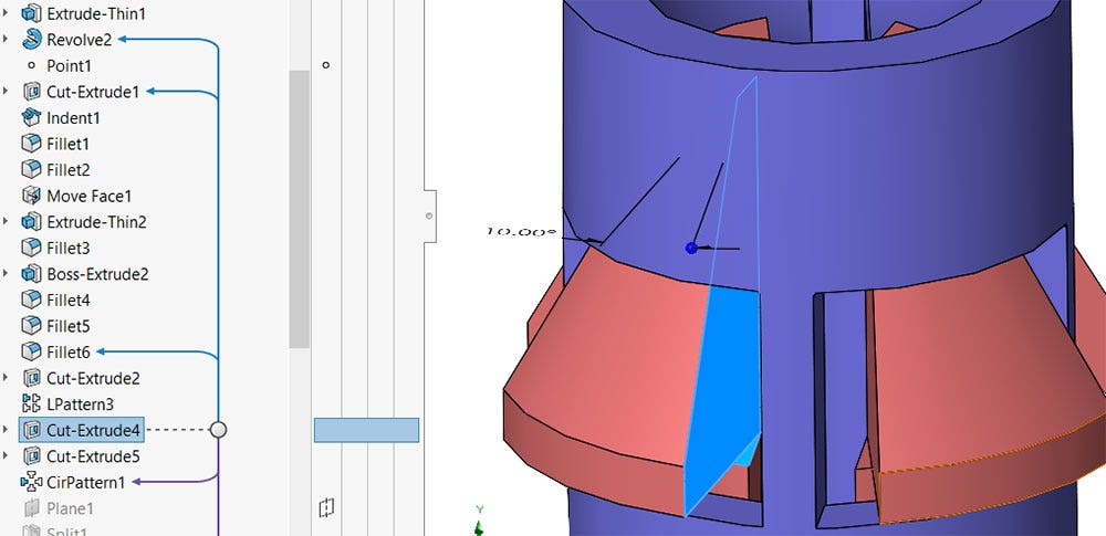
Unwanted geometry created from the cutting of the tab.
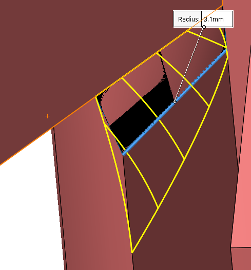
The approach I took was to create a lofted surface then use that surface to cut away the geometry I did not want and then use a fillet to create a nice blend.
The steps I took are as follows:
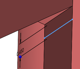
1. Sketch a profile for the loft on the vertical face which will be the bottom edge of the lofted surface.
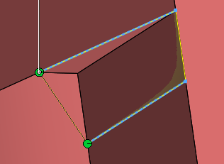
2. Create a lofted surface between the edge of the horizontal surface and the newly created sketch.
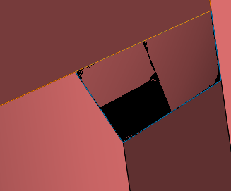
3. Use the surface to cut away the unwanted material.
4. Fillet the new edge for a smoother blend.
As we can see in the image above, this procedure has removed the undesired plateauing geometry and replaced it with a smooth transition.
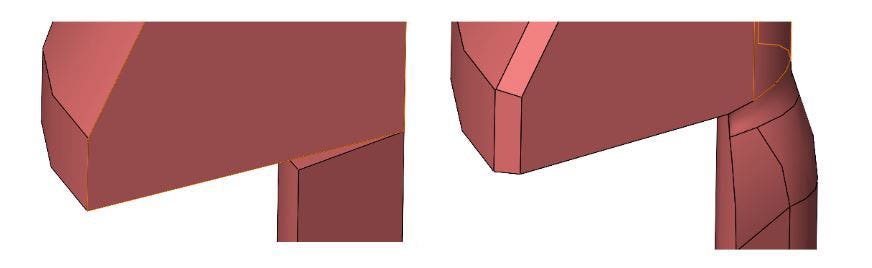
Side by side comparision of before and after the surface blending technique.
The Final Steps
The initial design of the pin was easily done using SOLIDWORKS with tools to model, confirm the manufacturing design constraints, and enforce those constraints using parametric relations. The next step to ensure the proper function of the pin is to validate the design using SOLIDWORKS Simulation. To learn more about how I used SOLIDWORKS Simulation to validate the design, check out the blog, “Validating a 3D Printed Compliant Mechanism Using SOLIDWORKS Simulation.”
Simulation of the compliant mechanism deforming and then returning to its original shape.
For more information on SOLIDWORKS tools or if you have any questions, contact us at Hawk Ridge Systems today. Thanks for reading!


