Locking pins are commonly used when assembly and disassembly are frequent and needs to be done quickly. Some common uses are vehicle hitches, adjustable scaffolding, telescoping arms, or basically anything with holes that needs a pin to align it. Traditionally, quick release pins are made up of multiple components and are spring-loaded, have a cotter pin, or a swinging wire to keep them in place.
In a previous blog, “Designing a 3D Printed Compliant Mechanism With SOLIDWORKS,” I reviewed the design process for this device. Today, I’ll review how I used SOLIDWORKS Simulation Premium to validate my complaint locking pin mechanism. The intention of the mechanism is to elastically deform so it can fit into a hole but once it passes through the hole it will return to its original shape and lock the pin in place.
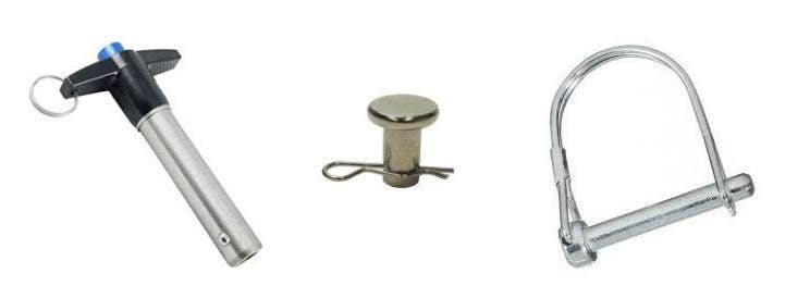
Examples of traditional quick release pins.
Designing a Compliant Mechanism
I have chosen to design a compliant mechanism that will act as a quick-release pin. A compliant mechanism uses the elasticity of the material to perform a mechanical function. In the case of the locking pin, instead of using a ball and spring, or swinging wire, the compliant mechanism will be elastically deformed when entering the hole and then return to its original shape once it passes through – kind of like a snap-fit. The compliant mechanism will be one component instead of multiple components needing assembly. This makes it ideal for the 3D printing process. You can see the compliant mechanism in action below.
The right view of the compliant mechanism elastically deforming to fit through a hole and then returning to its original shape to lock the pin in place (run in SOLIDWORKS Simulation).
Problems to Validate Using SOLIDWORKS Simulation
There are four potential issues I want to validate before I print this device and I have listed them below:
1. The tabs contract enough for the pin to clear the hole
2. There is enough internal space for the tabs to contract
3. There is no plastic deformation
4. A reasonable amount of force is applied
Why Non-Linear and Dynamic?
The answer to the dynamic portion of this question is easy. The part is moving through space and I would like it to be loaded and then unloaded, so a dynamic loading scenario. Since the loading is not constant and I am expecting motion, a dynamic study is necessary but why non-linear?
Since the definition of a compliant mechanism is for it to not permanently deform and stay in the material elastic range, you would think a static study would suffice. For other compliant mechanisms I have designed, that is entirely the case but this design is unique because it has some non-linear contacts. The non-linear contacts are on the snap fit faces that rub against the outer shell in order to contract. The contacting face of the inner part is changing its position and orientation as the simulation progresses. Since the face making contact is changing its orientation and deforming, this problem is more suited for a non-linear study. Looking at the top of the GIF above, you can see the faces of the tabs with the non-linear contacts.
Assumptions
The main assumptions for this study are that the material is homogeneous and isotropic and that the stress stay within the elastic range of the material. These assumptions are brought on by the limited material properties I could obtain for the 3D printed nylon used in the simulation.
Boundary Conditions
Fixtures
To ensure that the entire model did not accelerate into graphics space, I fixed the entire outside surface of the outer component. This gives all the nodes on those outer surfaces zero degress of freedom. I chose that many surfaces to reduce the overall degrees of freedom for the study. This fixture will definitely artificially stiffen the outer component, but that is not my area of interest in this study – making the fixture an acceptable choice.
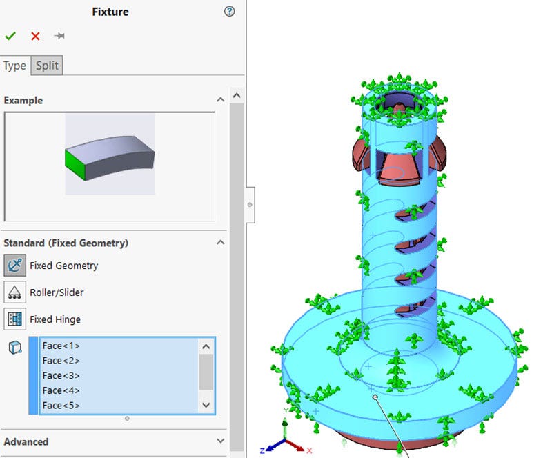
Fixtures used to constrain the model in 3D space and reduce the amount of degrees of freedom.
Loads
The loading in the simulation will be a prescribed displacement of the inner component until it makes contact at the bottom. The initial gap was 3.5 mm so the very bottom face of the inner component will displace 3.5 mm in the positive directions in one second and then be displaced back to its original position in one second. A time curve was used inside of the prescribed displacement.
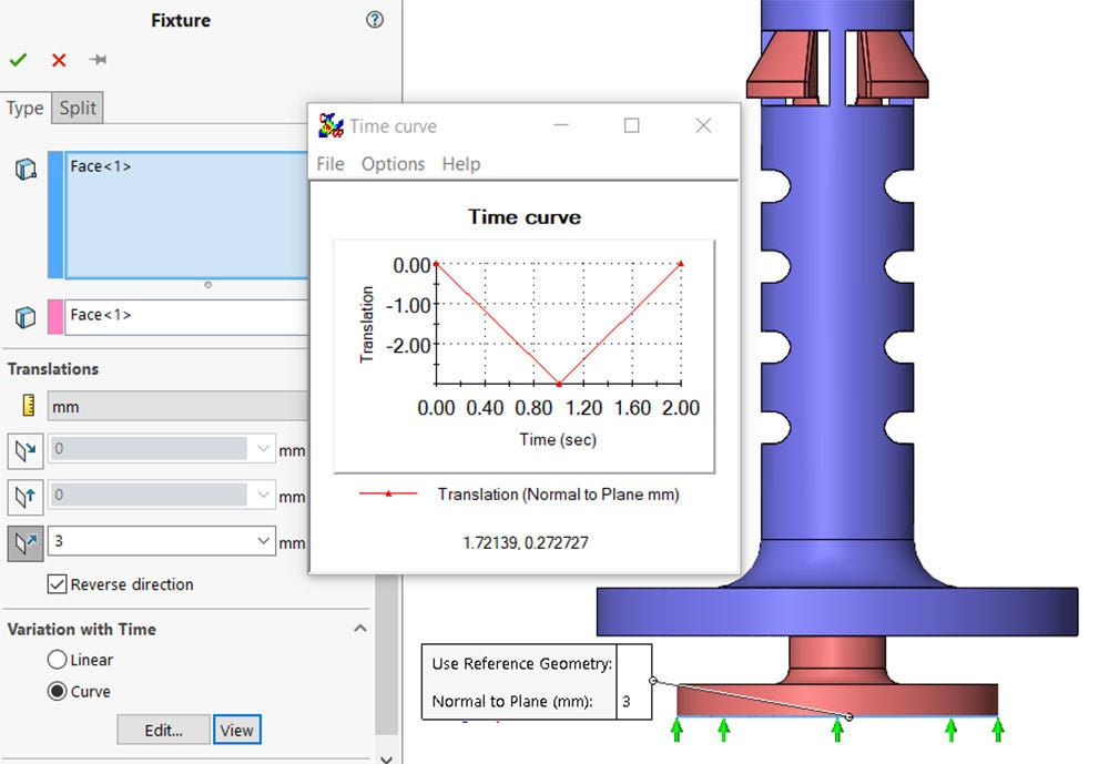
Dynamic loading applied to the model to displace the plunger 3mm in one second, then released to return to its original position in one second.
Connections
The connections were the most time consuming portion of the set up. I used 15 separate local contacts to define the potential collisions durring the simulation. I find naming my connections makes troubleshooting and changes a lot easier and the massive list of connections less indimidating because they can be categorized into smaller groups.
Ramps
This is the non-linear contact set and the main driving force of the compliant mechanism. As the red internal body is pushed upward, the blue faces will make contact with the purple faces. This local interaction was the biggest factor in the length of the simulation.
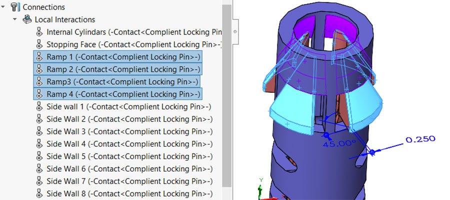
Local interaction defining the contact of the ramps on the tab.
Side Walls
The side walls would make contact if the internal body started to twist. Each compliant tab needed two contacts to mimic reality resulting in eight total contacts.
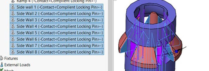
Local interactions defining the contact of the side walls.
Internal Cylinders
The internal cylinders were given a local interaction in case they made contact. This could occur if the long internal tabs buckled or had some extreme deformation. This was not an anticipated event but I wanted to cover all my bases.
Local interaction of the internal cylinders.
Stopping Faces
A local contact interaction was put on the face that will make contact when the plunger is pushed all the way in. I do not expect any contact to actually happen here as the prescribed displacement will stop as soon as they touch.
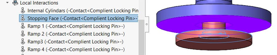
Local interaction on the stopping faces.
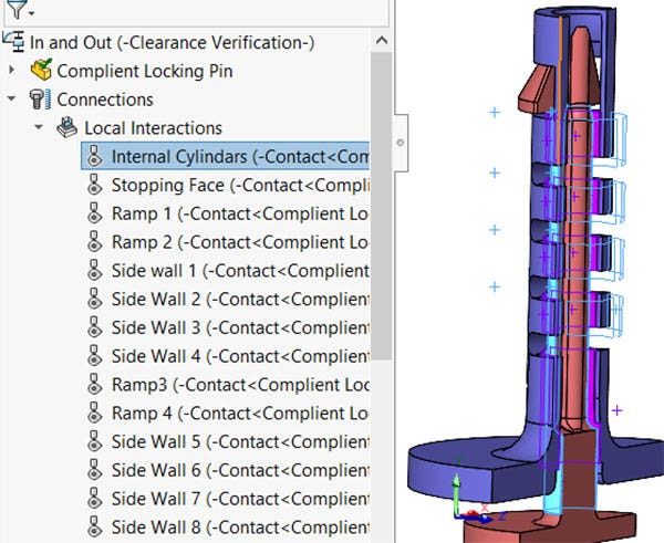
Interaction Viewer
The interaction viewer is a great tool to see all the different interactions in your model and make sure you are not missing any. Each interaction is listed in the property manager and displayed in the graphics area. The interactions are color-coded by type and you can choose to display the contacts for the entire model or individual component pairs.
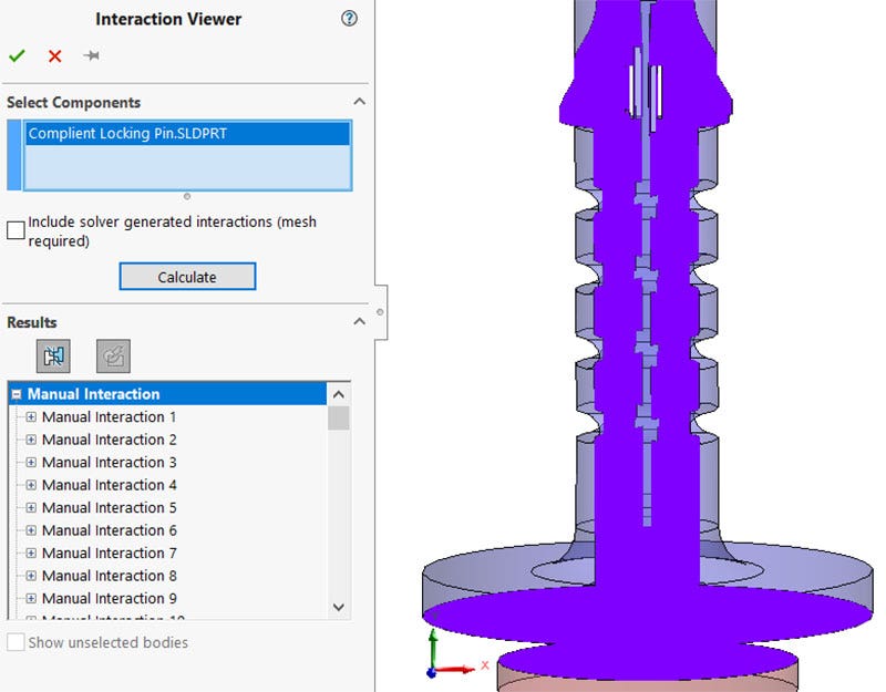
Interaction viewer showing all the contact interactions in purple.
Simulation Results
The results of the non-linear dynamic simulation showed positive results that gave me to confidence to print the design. All four of the problems I wanted to validate passed. In this section, I will reiterate the problem and the post processing used to prove it successful.
The tabs contract enough for the pin to clear the hole
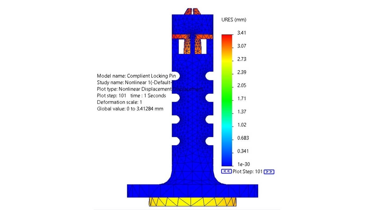
In order for the mechanism to be a locking pin, it had to contract enough to fit inside of a hole but have a portion larger than the hole to lock it in place when at rest. At zero strain, the tabs of the pin stick out wider than the nominal diameter of the desired hole. The intention of the dynamic simulation was the make sure that when loaded and the tab contracted, it was small enough to pass through the hole. Using a displacement plot with a 1:1 deformation scale at the timestep of maximum contraction, when the plunger was pushed all the way in (t=1s), I could visually see that the contracted tabs are aligned with the outer diameter of the outer body. This contraction would allow the pin to easily pass through a hole when the compliant mechanism is activated. The image below is a deformation plot one second into the simulation where the tabs are fully contracted.
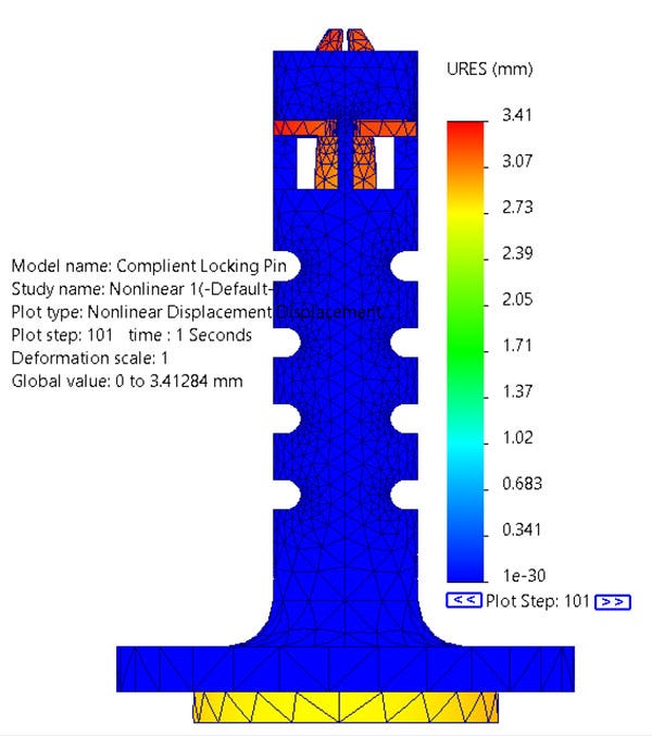
The one second time step where the displacement is the highest.
To further validate this result, I decided to see how much of the resoluting elastic deformation is in the radial direction. Plotting the displacement in cylindrical coordinates gave me a maximum radial deformation of 1.33mm on the outer face of the tab with an average of 124 mm. The original model had an original overlap of 1.25 mm. The results of the radial displacement quantifiably prove that the tab contracts enough to fit through a hole since there is a hole clearance already built into the diameter of the outer pin.
There is enough internal space for the tabs to contract
The next concern I had was if there was enough internal space between the tabs to allow for enough contraction. To verify this issue, I used the same displacement plot at the same time step but from a different view. Looking axially into the cylinders, I can see that when the plunger makes contact with the tabs at the one second time step, there is still space between the inner faces of the tabs.
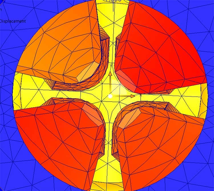
Displacement plot at the maximum displacement time step of one second showing the clearance between the inner faces of the tabs.
There is no plastic deformation
To ensure the mechanism is actually compliant, all the deformation has to be within the elastic range of the material. In short, this means that the part will return to its original shape after the loading is removed. The nylon 12 material used has a yield strength of 48 MPa. The stress plot shown in the GIF below shows the maximum applied stress during the simulation is 12.6 MPa. This value is well below yield giving me the confidence that the stresses are within the elastic range of the material and the mechanism will be compliant.
Von mises stress plot over the full simulation showing a maximum stress of 12.6 MPA.
A reasonable amount of force is applied
The final conformation to validate the design is to understand how much force is needed to put the mechanism in the contracted position. Since a prescribed displacement was used to move the plunger, all I needed to do was plot the reaction force required to depress the plunger. The image below shows that the maximum applied force for the compliant mechanism is 4.57 N or about one pound of force. This is a very easy force for a human to overcome, but is more than the weight of the object so it will not naturally force itself out of position under its own weight. I might be concerned with it being too easy to remove but this result warrants a physical prototype to feel out.
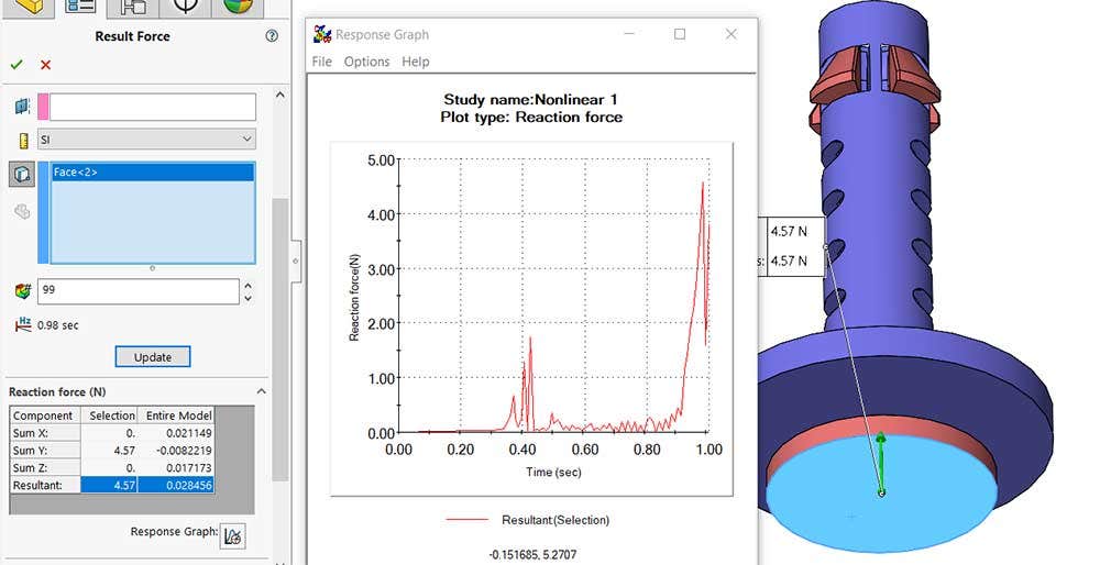
Reaction force on the plunger face demonstrating how much force is required to cause displacement.
Design Validation Conclusion
Using SOLIDWORKS Simulation Premium, I validated the design of my compliant locking pin mechanism. It passed all four of the problems I wanted to validate; it contracted enough to clear the hole, had enough internal space to contract, did not plastically deform, and required a reasonable amount of force to deform. SOLIDWORKS was the perfect tool to design, validate, and export to manufacturing for my project and I am very happy with the results.
GIF of compliant mechanism displacement with no simulation result plots overlayed.
For more information on using SOLIDWORKS tools or if you have any questions, contact us at Hawk Ridge Systems today. Thanks for reading!


