Why We Render 3D Scans
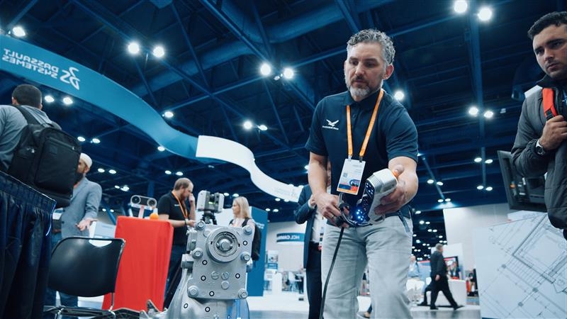
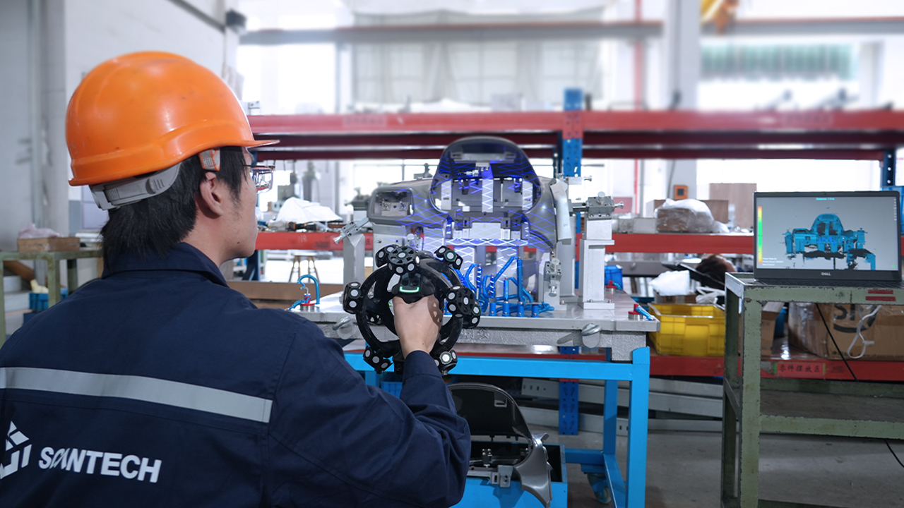
3D scanning of an item has a variety of uses such as reverse engineering and inspection. Another use for scanning manufactured or demo parts is creating realistic renders of objects that look similar to their real-world counterpart quickly but with different lighting and/or coloring.
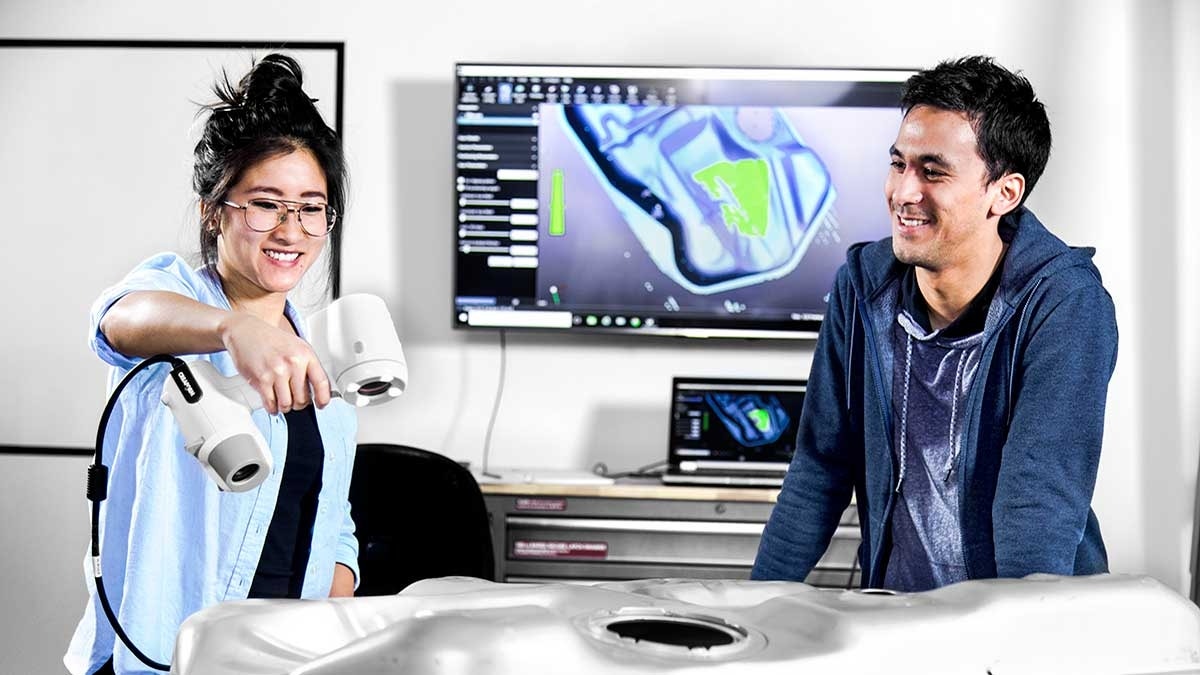
Whether for product display on websites, showing prototypes for customers, or seeing how a product will look with new colors, this can all be done in rendering software like SOLIDWORKS Visualize. Learn more about the different options for SOLIDWORKS Visualize in this article.
In this blog, we’ll discuss what material properties can be adjusted to improve renders and how they can make a huge difference for your renders. The rendering software shown is SOLIDWORKS Visualize, but these concepts are general in nature and can easily be applied to other rendering software.
Regardless of whether you are using a scanner that captures color, like an Artec 3D scanner or a laser scanner and then applying color later, you’ll need to render the scan to create realistic photos. Using a 3D scanner for rendering the data saves significant time in the modeling process. But if you can’t get the digital texture to match the real-world object, your render may appear odd.
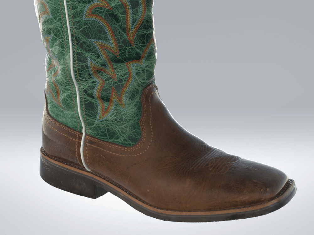
For example, below is a render with high gloss. Read more about how to apply textures to your 3D models in this tutorial article.
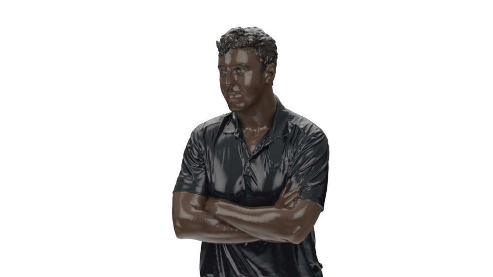
To make a render “pop” and appear realistic, there is another factor to account for beyond the mesh bodies resolution: the texture material of your 3D scanned mesh body.
This material is made of several layers: Albido, diffuse, bump, and metallic are just a few. These are applied to the mesh body and mapped along the body with a UV map.
The Albido, or color, will be the reds or greens that appear on the mesh, but material properties like diffuse and metallic drive the gloss or matte appearance during the rendering process.
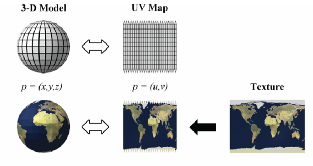
What is a UV Color Map and How Does it Relate to 3D Scans?
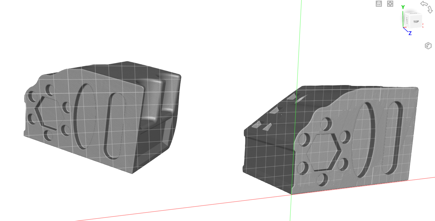
Before diving into the material properties, we first have to talk about UV mapping. If you’ve ever seen a mesh file, you’ll find it is made of polygons, which create the mesh shape. You can assign a UV map to these polygons. A UV map is a flattened display of the colors and material properties of the mesh and includes information about how they are assigned to the various polygons.
Think of this as having a CAD solid body made of surfaces and then a color applied to the surfaces. The UV map is applied to the polygon’s normal side and wraps around the mesh file based on the UV map layout. This is how material properties and color are assigned to the various polygons along the mesh, depending on the number and complexity of the polygons, the map can vary in size and layout.
If a UV map is not properly applied to a mesh body, then the render may not ever turn out properly since the polygons won’t display correctly. It’s best to check that a UV map is properly overlaid before experimenting with material properties. Improper features can be things such as flipped-normal of a polygon or non-manifold sections of a mesh.
How Do Material Properties Affect a Mesh?
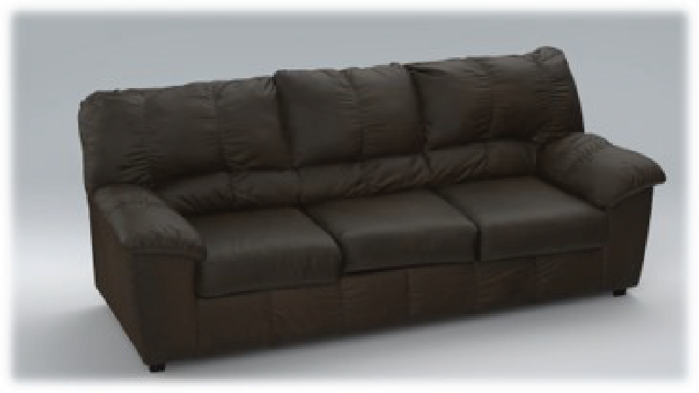
If you don’t match the material properties of the mesh to the real-world object, you can create an odd appearance within the render. Thankfully, it’s easy to adjust these properties within rendering software once you know some of the driving factors. For example, look at the rendering of this couch rendered with a matte material finish.
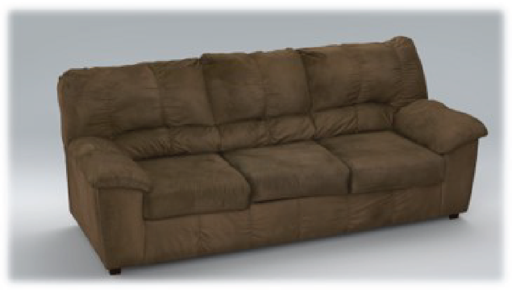
A matte finish means that there is little to no gloss or shine, giving the couch a felt-like material appearance. If we adjust a few properties to match leather, such as increasing shine and roughness, the couch now appears significantly different despite the color not changing. This is due to the material properties of the mesh changing, but not the color applied to it from the scanner.
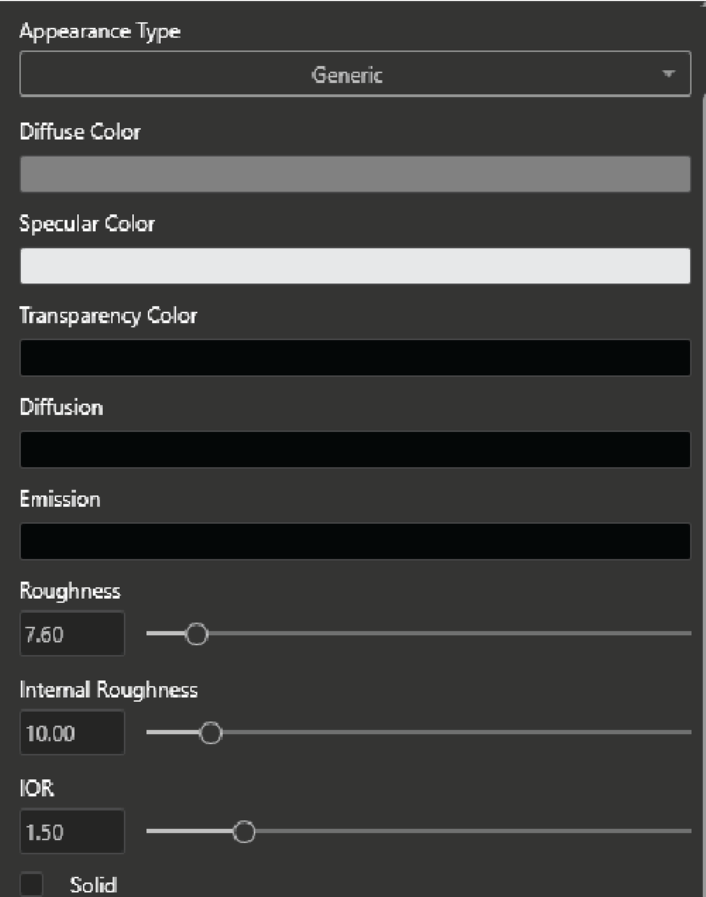
You may see terms such as PBR (Physical-Based Rendering) materials within SOLIDWORKS Visualize or other rendering software. These are materials that have customized settings related to different material properties such as diffusion, gloss, and emission to match certain physical properties when a light is shined on them. For example, certain metals like aluminum vs. cast steel will have different levels of shine, roughness, and diffusion to reflect light. It’s common to see PBR materials used and created for 3D scanned meshes that only keep the albedo material layer originally since we can keep the color layer the same and optimize the material properties separately.
Adjustments for Mesh Appearance
Here’s a quick rundown of different adjustments and how they affect mesh appearance:
Metallic
Controls how metallic the material will appear. If it’s made of a metal material then we set the bar to max, if not, then to zero.
Roughness
How polished a surface will appear and scatter reflected light. Increasing this will reduce the shine of a part.
Clearcoat
A shiny wet coating to add additional plastic gloss to a part.
Transparency
Affects how the base color and specular color compete and shows one over the other.
Emission
Light emitted from the part, increasing this adds a glow effect to parts.
Creating Better 3D Renders with SOLIDWORKS Visualize
By understanding both the UV mapping of a textured material and the layers associated with materials, you can fine-tune the look of a 3D scan and set up amazing renders within SOLIDWORKS Visualize! Further adjustments to lighting and background can make a quick scene for a product.
If you are interested in learning more about 3D scanning or SOLIDWORKS Visualize check out our YouTube page, or reach out to Hawk Ridge Systems.