
Need to add a touch of realism to your 3D model? In this article, we’ll walk you through how to scan an object to create a detailed mesh that you can use to apply realistic-looking detail to your 3D models.
The process of creating a mesh from photos is called photogrammetry, and it’s ideal if you’re looking to reduce post-processing time. These mesh bodies typically have great color texture but poor mesh detail. We’re going to use a camera to capture photos of a controller within Artec Studio so you can not only get crisp color quality but ensure the lighting around the part is extremely detailed for that extra bit of realism on your 3D models.
More of a visual learner? Check out our YouTube tutorial on how to apply textures in Artec Studio.
We’ll discuss the steps and tips to use this texturing tool within Artec Studio using a plastic game controller as an example, which can have difficulties being textured because the plastic is shiny and reflective.
Scanning Workflow to Apply Textures to your 3D Model
Before going deep into the setup, let’s first discuss the workflow to use this tool. The steps involved are:
- Create a scan of the object in one orientation using the Artec3D Scanner.
- Using a DSLR camera, capture the object in the same position scanned in at various angles.
- Reposition the object into a second orientation and scan the object.
- Capture a new set of photos of the object in the new orientation.
- Repeat for as many orientations as needed to create a mesh from the scans.
- Process the scan data until you have a mesh with texture pulled from the scans.
- Import the photos captured from the camera into Artec Studio in individual groups based on the camera’s position. Remember, if you moved the camera, then it’s a new group.
- Enable one scan, the mesh with texture, and a group of photos captured while the object was orientated in the scan and run the Photo Registration tool. Repeat for all groups of photos.
- Run a new texture process on the mesh using the photo textures only.
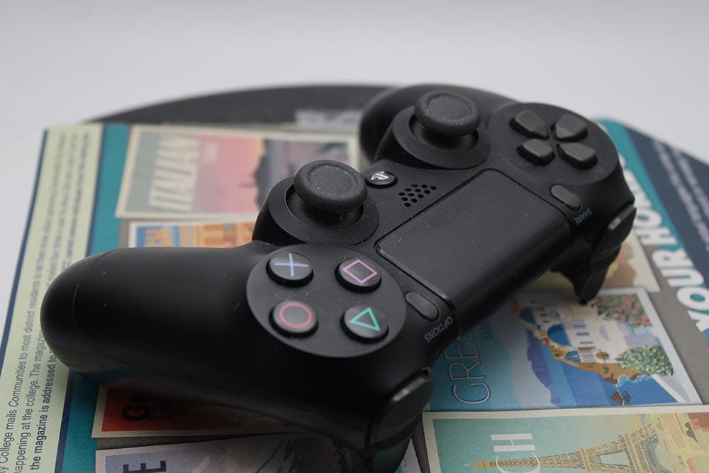
Your project may look similar to the image below after running this process:
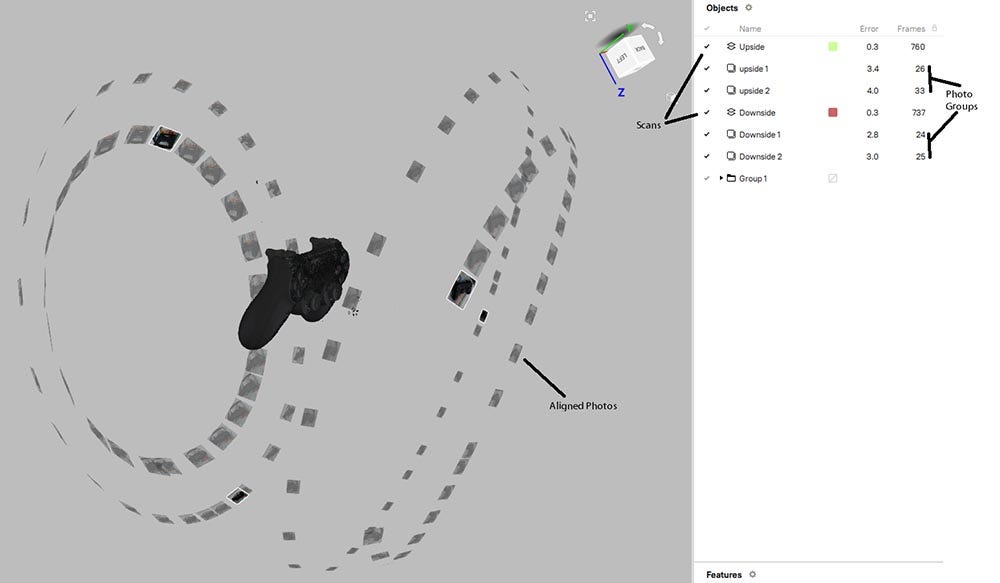
This workflow has several steps, but it is only three steps that are repeated based on the number of positions the part is orientated in to scan. We want to scan an object, capture photos of the object in that position, process the data into a mesh, align the photos to the mesh, then re-process the mesh with the photo texture. The quality of the photo texture, however, is based on how well the photos are taken, and with a proper setup, you can minimize the risk of having to re-scan and take new photos of the object.
Setting Up an Object for Photo Capture
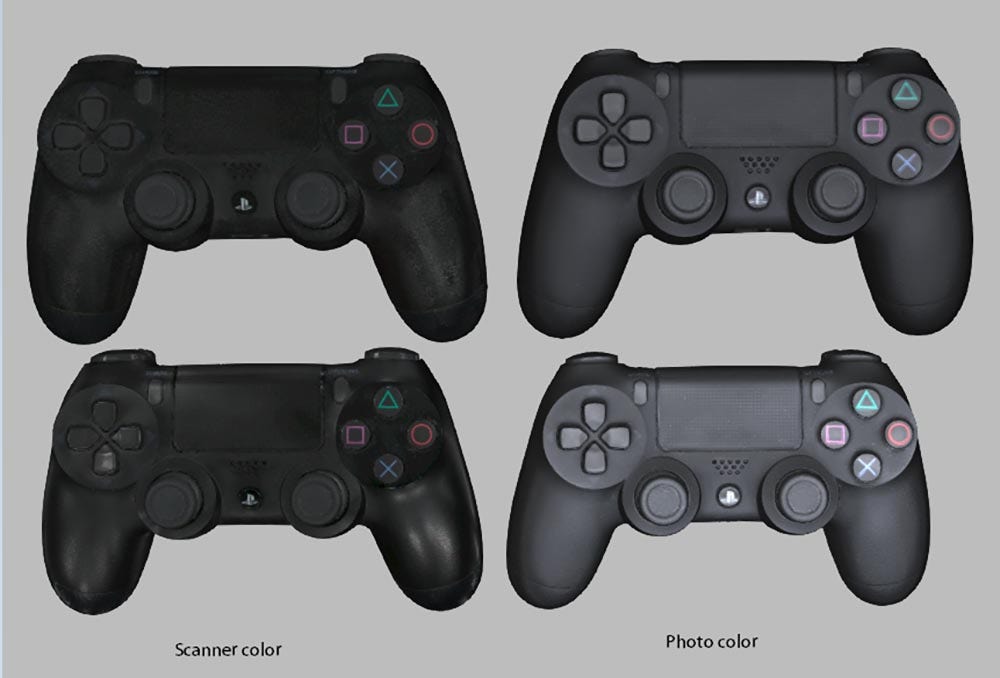
The first step in the photo texturing process is creating a proper space to capture the photos. The object cannot be disturbed from the original scanning position, so the lighting will need to be set up around the part or the space is easy to transfer the part into. For small objects that can be scanned with the Artec Space Spider, we can use a photo booth that provides even lighting around the part in the scanning space. We also want to diffuse the lighting, so we have as little direct light as possible on the part. We can see from the example below that when the light isn’t defused, we have spots on the plastic that sharply outline our light source, which can confuse the alignment process.
If you are scanning a larger object that cannot be placed into a photo booth, having a diffused light is important, but also having proper space to walk around the object is too.

For the photos to align well, we will also need to have good geometry or color information around the object. By scanning the object on a colored map or placing small objects/stickers around the part these can act as anchors for the camera photos to match with the scans. For larger objects, this isn’t needed as much since there’s plenty to reference for alignment on the part, but for smaller objects, it’s required to have a color-rich surface to scan on top of to help with alignment.
For some objects, diffusing the light isn’t enough, and a combination of tools are needed. Using a dulling spray can apply a matte finish to the surface of an object which reduces the glare from the lens and lighting. Combining dulling spray, polarization lens, and diffused light helps stop the concentration of lighting on parts.
Tips and Tricks for Capturing Photos to Apply 3D Textures
When capturing photos two factors heavily affect the alignment process, object focus and overlapping data. Without having a consistent and even focus on the object in the photo, the color projected onto the mesh may become blurred and improperly scaled to the mesh. If you are taking multiple angles in an orientation break the angles into individual groups but maintain the same shutter and focus. If the focus is adjusted between photos, you risk having the photos improperly aligning with the scan.
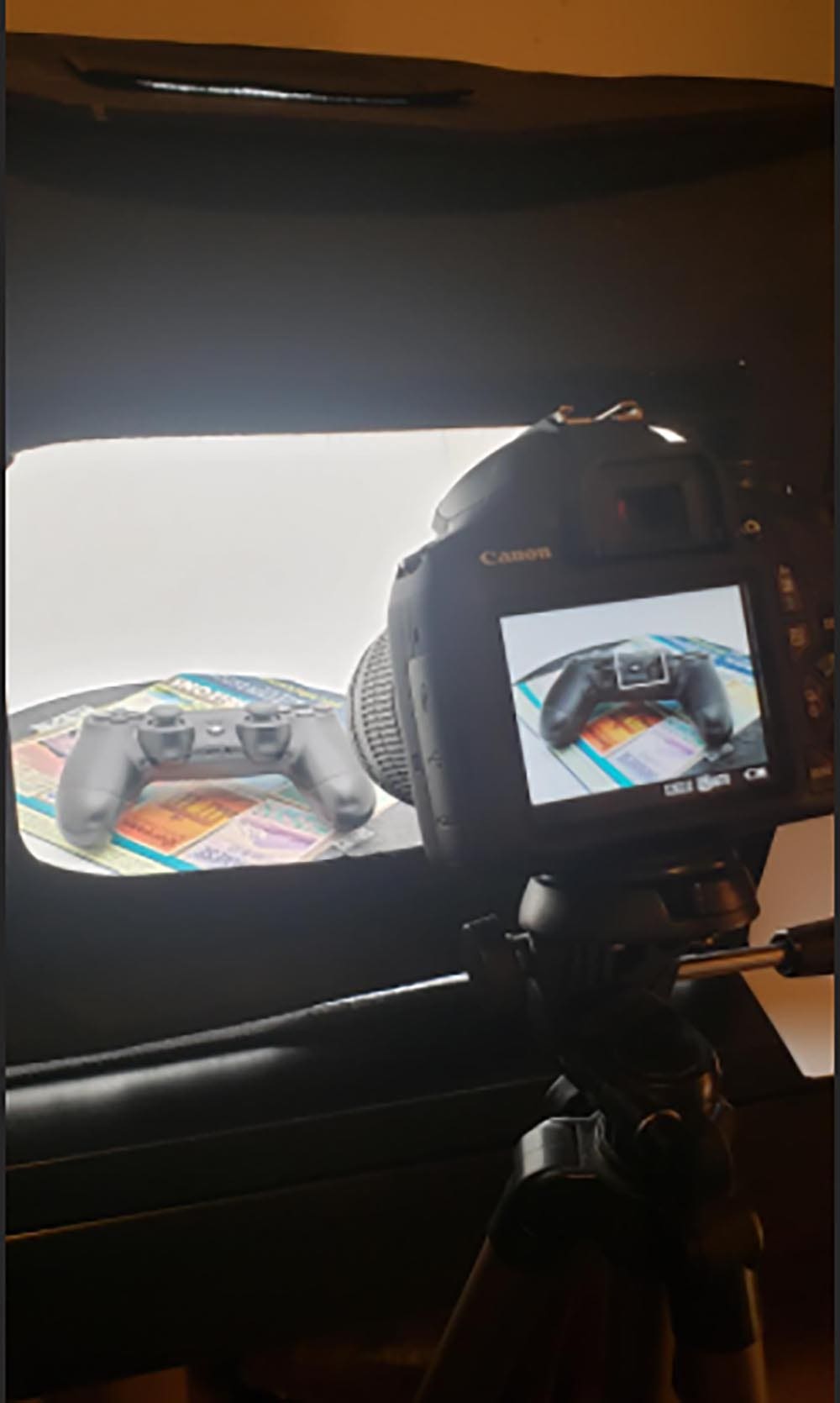
The setup above has the object in the center of the camera’s focus with a shutter speed that works with the lighting inside the box. Additionally, the camera is set to manual focus, so it doesn’t change while we rotate the part. A trick is to zoom into the part using the camera’s digital focus (not zooming the lens in) so you can verify if the camera sees the smaller details well. You don’t have to have close-up shots of the part to get smaller details, they just need to be visible if zoomed into the photo.
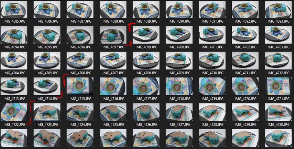
The number of photos varies by the size of the part. Ideally, you want an 85% overlap between photos so they can properly be aligned with the object taking up 90% within the photo. Scanning the object on a turntable is great for this since you can constantly rotate the part without having to adjust its position or the camera. For this mesh scan, 115 photos were taken in 4 different groups, giving plenty of overlap and having 2 angles of photos per orientation of the part.
This set of photos is broken into 4 groups based on the camera’s angle when taking photos.
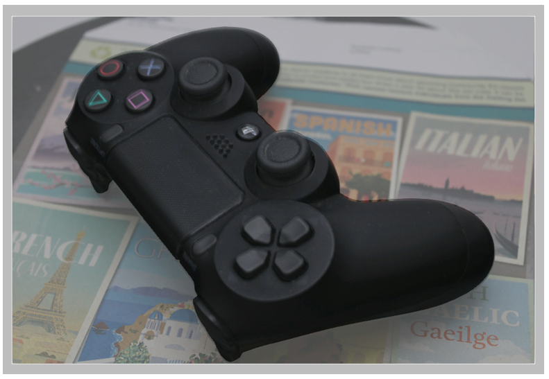
Below is an example of a perfect photo due to the even lighting on the object, color information for alignment, and the entire part within the photo.
How to Import and Process Photos for Applying Realistic Textures to Your 3D Models
Once the photos have been captured, they can be imported into Artec Studio using the File -> import -> Imported Photos option. You can select multiple photos at once and import them as a single group, but if Artec Studio detects that some photos have different focal lengths it will attempt to re-group based on focal settings.
To align the photos to the scan, enable a mesh that has had texture applied to it, a photo set, and the scan associated with that photo sets orientation. With all these enabled, the Photo Registration tool will become available to run. There are two settings within this tool:
- Image Pre-processing – Adjust the contrast of the photos before an alignment
- Feature Density – Account for multiple materials on the object that may affect lighting
For this controller, the image pre-processing was enabled to add extra lighting to the object, and the feature density is set to high since we have matte plastic, shiny plastic, and colored paper all within the photo.
When the process is done, you’ll see the photos within the group in the 3D space around the mesh, which can be individually clicked to check how well they align with the mesh. You can delete or exclude photos that didn’t match well and have a high error value (above 4). Below is an example of a photo overlaid with the mesh to compare the two:
Applying Textures to Your 3D Models
After each group of photos has been aligned to the mesh the final step is to re-apply the texture to the mesh using these photos. Within the texture tool, you can use the Reuse UV map option to save time with applying the texture by using the existing UV map generated from the scan’s texture. It’s recommended to duplicate the mesh before re-running the texture process, so you don’t override the initial mesh. Glare reduction can also be used during the texturing process.
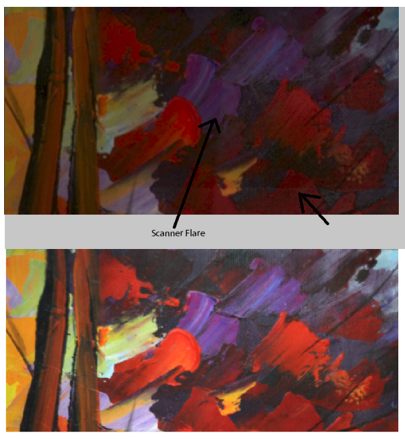
You can also use the scanner’s texture along with the photo textures to combine the two. This doesn’t work well for shiny material that reflects the scanner’s light, but for glossy surfaces, it can work well. Below is an example of a painting scanned with the EVA. There are separations in the coloring from the scanner’s texture due to the scanner reflecting light at different angles. There are sections of the frame that may be hard to capture via photos so we will combine photo textures with the scan color. With photo textures, the color is brighter and has even lighting throughout the mesh without any missing spots.
The texture applied via the photos is treated like the normal scan textures. The saturation, hue, and contrast can be adjusted further and exported as a .obj or .ply once finished.
The ability to use photo texture for 3D models vastly improves the quality of the mesh color depending on the material of the object. With the custom lighting capabilities material, like shiny black, can be properly applied to a mesh. By having a proper setup and understanding of the camera’s shutter and aperture, the photos taken for the texturing process can be evenly and consistently applied to the mesh.
Interested in learning more about Artec Studio 17? Watch the Artec Studio introduction video to learn more.
If you have questions about Artec Studio or just want to learn more about applying textures to your 3D models, contact us at Hawk Ridge Systems.


