
In design and manufacturing, applying text to parts can be a critically essential tool. From basic part numbers and functional indicators to brand decals and customized insignia, there is a wide range of necessary text functions. Understanding the capabilities of SOLIDWORKS to best utilize the letters, numbers, and/or symbols will be a very helpful skillset to put your specific design intentions into action. Whether engraved, embossed, or 3D printed, it all starts on a foundational sketch level, so let’s start with the initial setup.
Sketch Text Setup Considerations
Just like a standard sketch, the text must be drawn on a plane or planar face.
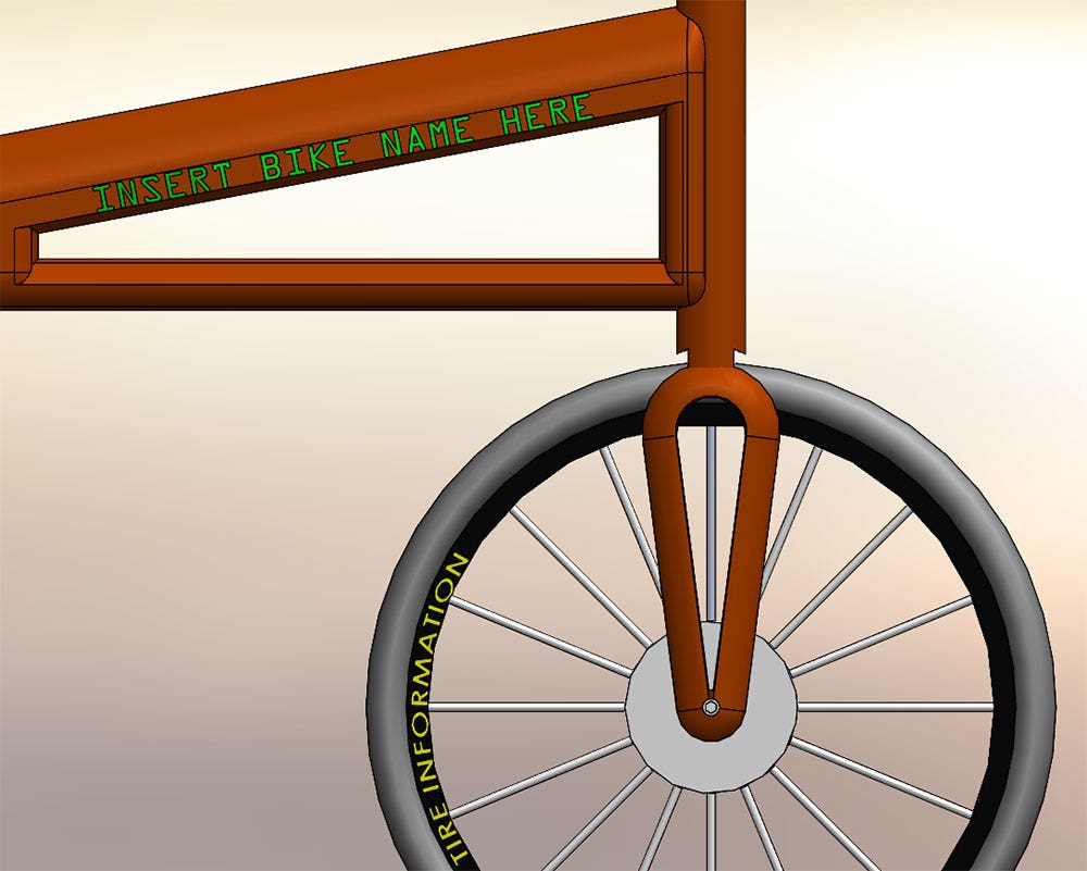
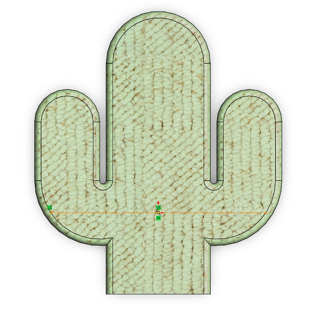
Once you have your sketch plane, it is a good idea to think about what geometry you want to use to position your text to your desired location. Text can be guided by lines or curved features such as arcs, circles, or splines. See the bike image above for two examples driven by different part edges. Additionally, using sketch relations is an effective way to drive your text to an exact position that will regenerate for all revisions or configurations. In the cactus-shaped part below, a horizontal line was drawn with a midpoint relation to the origin and coincident relation to an outside edge. Through these conditions, the text will remain positioned in the widest useable area even if the geometric part dimensions are modified.
Customization Options
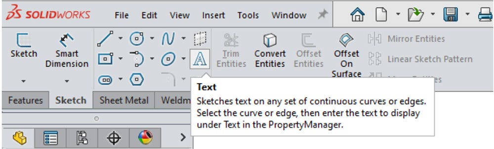
Now that you have the curve, click the Text icon, shown below in the Sketch tab of the Command Manager toolbar at the top of your screen (or Tools > Sketch Entities > Text) to open the Sketch Text PropertyManager, also shown below.
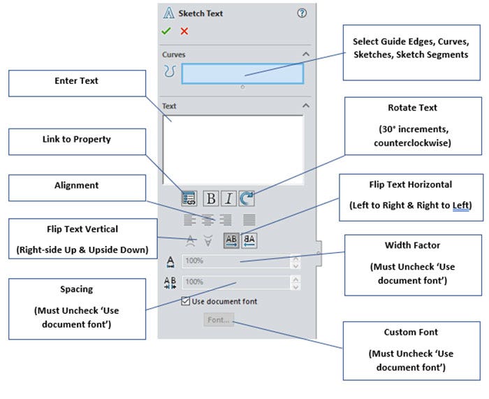
Most of the above selections are self-explanatory, but I will expand on a couple of features that could save you considerable time and frustration.
It’s worth noting that the “Link to Property” option allows you to link the value of a document property, custom property, or configuration-specific property to a text entity. If using a design table or bill of materials (BOM) to link values, the text will automatically update to match these driving inputs. Alternatively, you can manually enter properties to link in the text box with the syntax $PRP:”PartNo” (substitute PartNo for any established property), though this method is susceptible to display errors if there are any syntax typos.
There is an option to change the rotation angle and direction to more specific values. After clicking “Rotate Text” the text box will display the syntax
Unchecking “Use document font” will allow you to change the font and text height (in points or document units) as well as showing the options for bold-italic, strikeout, and underline. If your fabrication process requires stick font, this would also be the location to adjust for that. Stick font, or single line, stroke, or open loop font, must meet certain standards for manufacturing depending on machine type such as Computer Numerical Control (CNC), water jet, or a specific labeler or engraver.
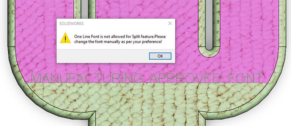
Unless your organization has a custom specified stick font, SOLIDWORKS recommends using OLF SimpleSansOC Regular font for all stick fonts. Keep in mind that this font cannot be used with the extrude, cut, or split line features (see error message below), so making sure the sketch is visible and not hidden for manufacturing drawings or CAM functions is advised.
To remove the text categorization and simply have the letters/numbers/symbols recognized as sketch geometry (lines, arcs, splines, etc.), SOLIDWORKS gives you the option to dissolve sketch text into separate sketch entities. To do this, in an open sketch, right-click the text (you will see the pointer change to the Text [‘A’] icon when it is over the text) and select “Dissolve Sketch Text.”
Converting Text into 3D Model Features
Once you have your sketch text style and positioning all formatted to your required specs, you can proceed with any model features to make your insignia stand out (or carve in, depending on preference). Extruded bosses and cuts are commonly used sketch text features as well as implementing a split line option or wrap (not covered here, see link below) to project the text onto your model.
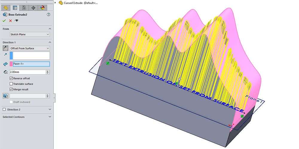
Depending on your part geometry and sketch text plane location, utilizing extrusions to add to remove material can be a very simple process, especially to planar faces. For projecting text on non-planar surfaces, one useful feature is the end condition “Offset from Surface.” With the sketch with your text selected, click the “Extruded Boss/Base feature.” Then after choosing the “Offset from Surface” end condition, pick the curved face for the “Face/Plane” as seen in pink below.
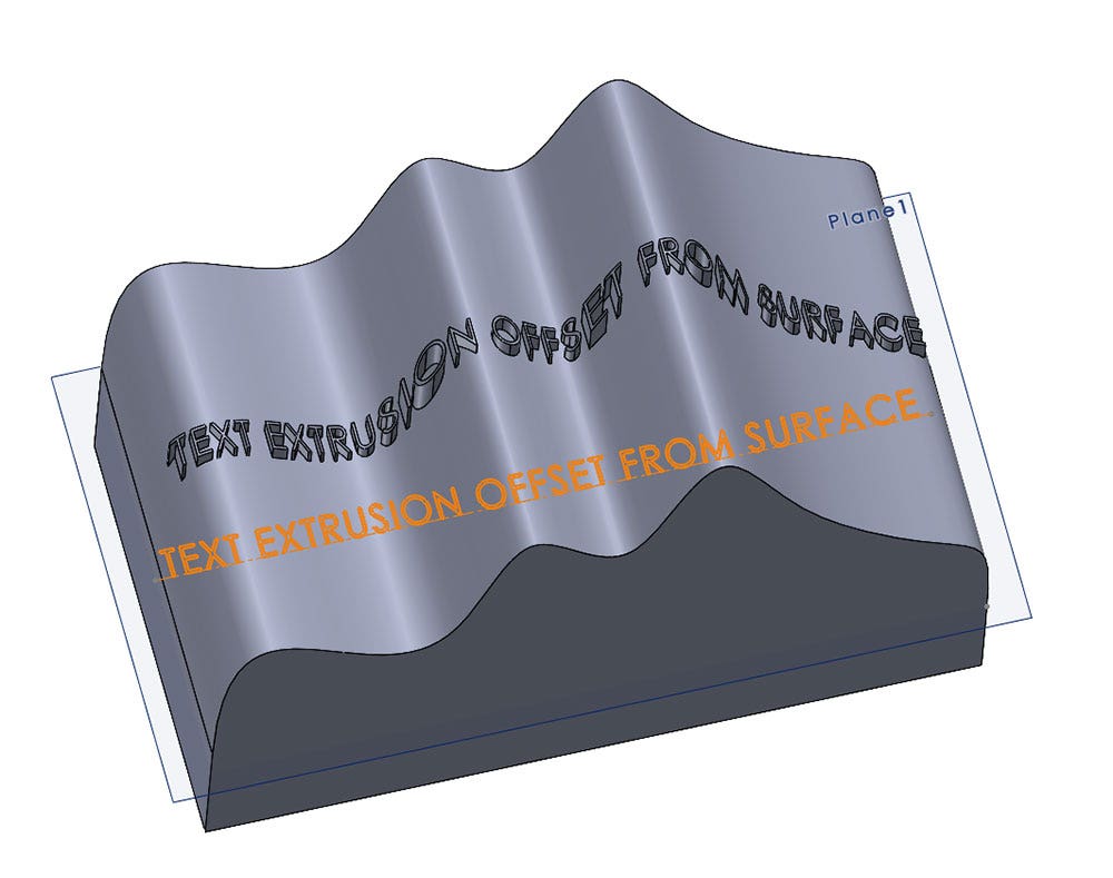
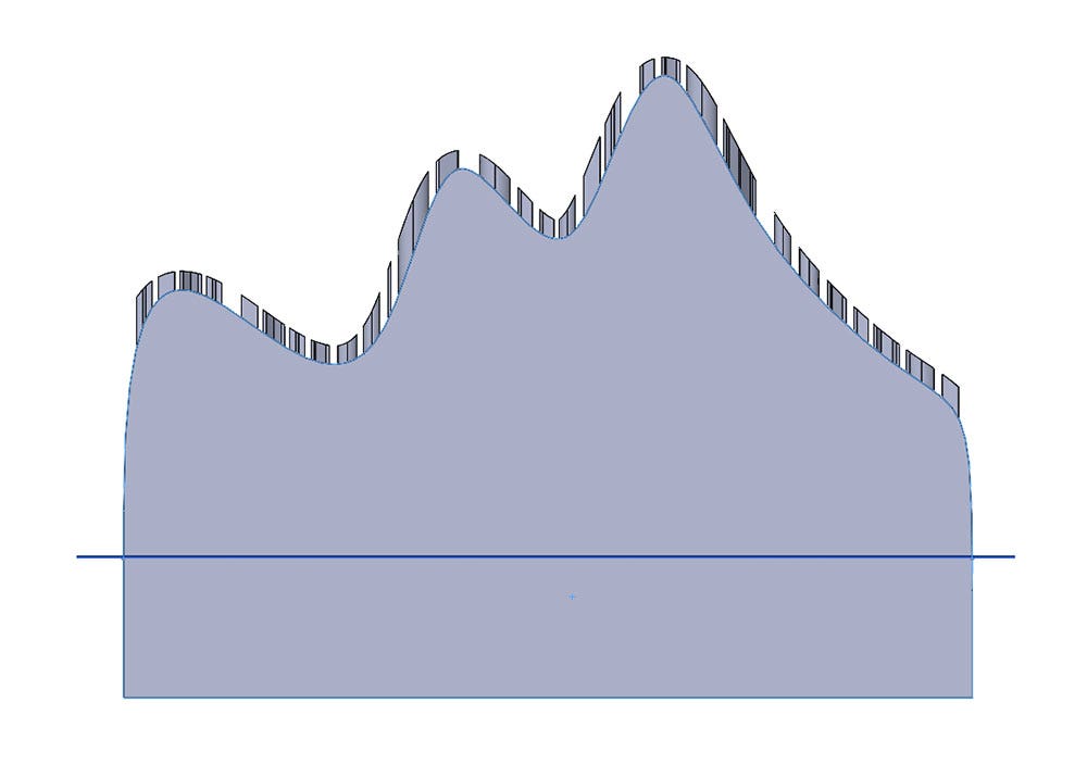
Setting the “Offset Distance” (2.00mm in this example) creates the text height normal to the non-planar surface as you can see in the isometric and profile views below. You may have to toggle the “Reverse Direction” and check/uncheck the “Reverse offset” options to match the desired orientation of the arrow shown in the graphics area.
Using the ‘Wrap’ feature is an additional method that can be very useful for non-planar surfaces. Check out our blog, “Wrapping Text Onto A Conical Face in SOLIDWORKS,” for an example.
Finally, to put it all together, the “Split Line” feature will be used to project a 2D, driving spline curve onto a spherical surface. Clicking the Split Line icon under the Curves dropdown in the Features tab of the Command Manager toolbar at the top of your screen (or Insert > Curve > Split Line) will bring up the below menu in the PropertyManager.
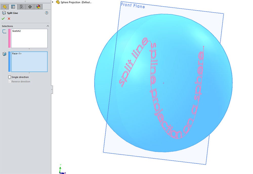
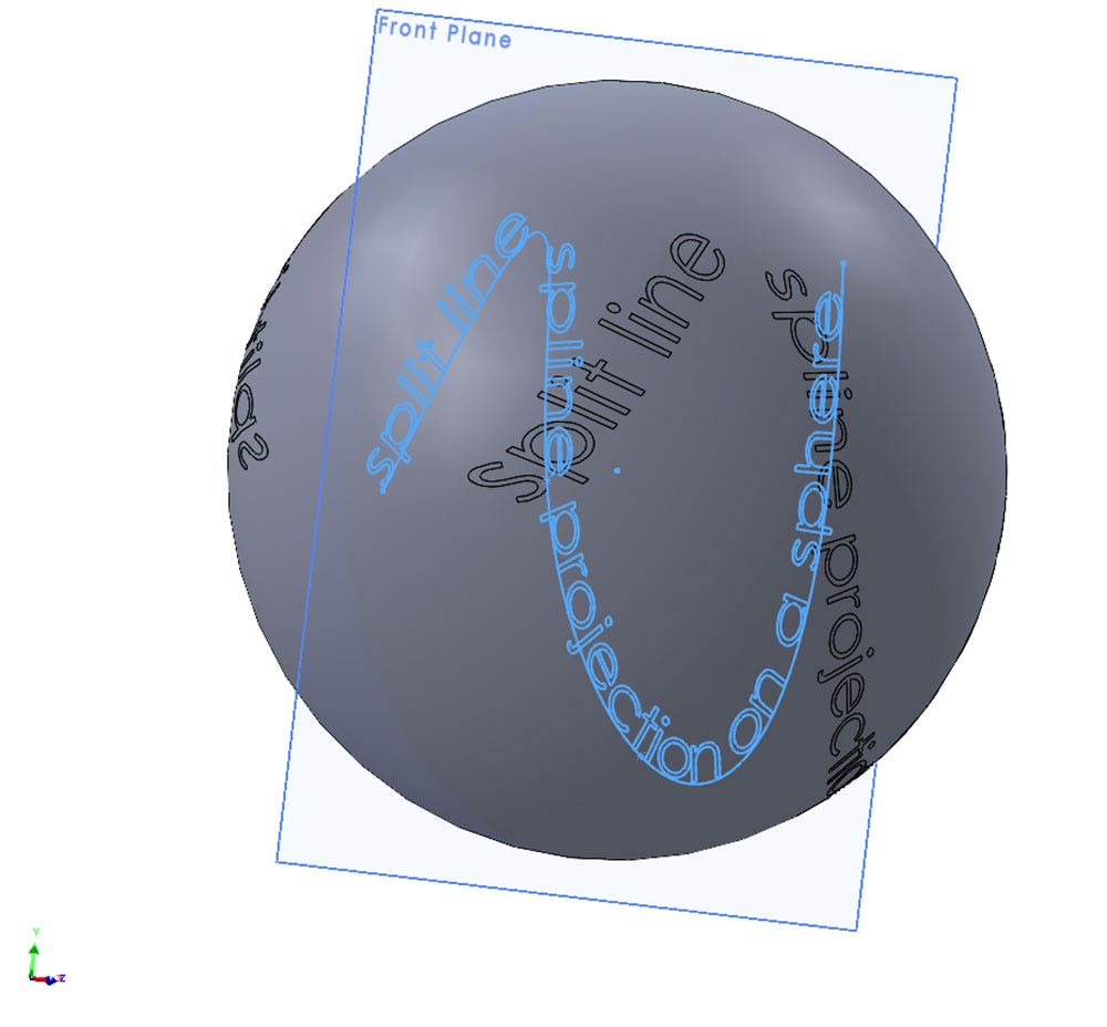
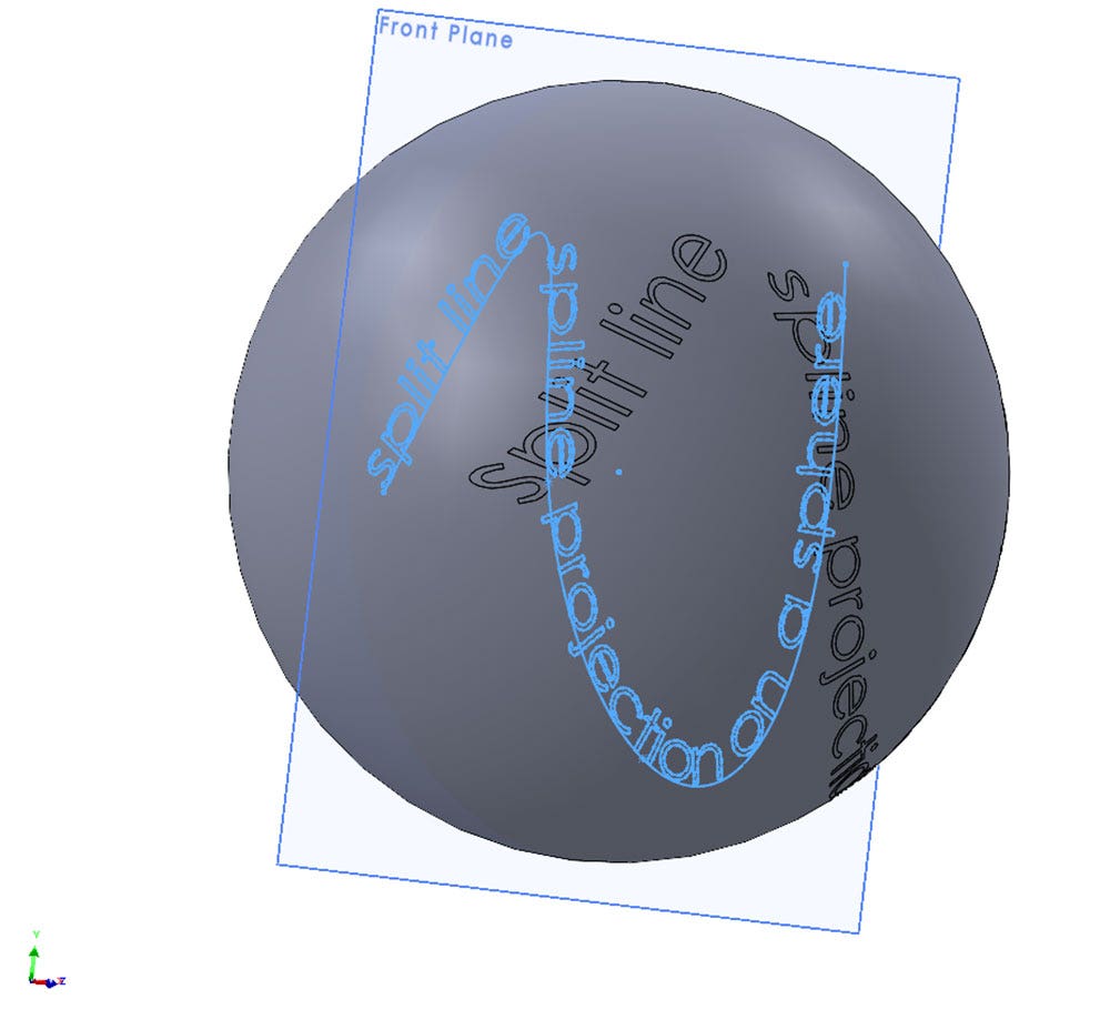
Select the text sketch in the first box for the “Sketch to Project” and the sphere’s face in the second box for the “Faces to Split.” The text plane is on the front plane which is symmetrical to the origin of the sphere so the option to project in a single direction or both directions is relevant. Without checking “Single direction,” you can see in the first image below shows the text emitted on both sides of the sphere’s core, displaying both forward and backward, whereas the second image displays just one side with the text forward.
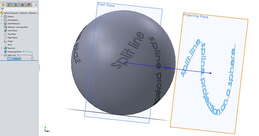
Alternatively, if the text plane is on one side of the sphere as shown below in the “Projecting Plane,” it will not matter if a single direction is selected, completely splitting the body with the separated text surfaces.
Once you feel comfortable with using these tools within SOLIDWORKS, there is no limit to the combination of unique text purposes, types, or appearances that you can customize. Thanks for reading, and if you have any questions, contact us at Hawk Ridge Systems today. Viva la sketch text!


