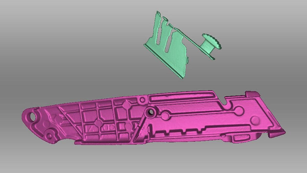
Assembly scans are useful in several ways. They are typically more detailed and complete than single scans and can include features that would not be visible or scannable without disassembly. They are useful for viewing internal components and can even be used for diagnosing motion systems.
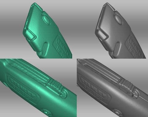
A comparison between scans done with and without disassembly. The quality of the scans on the right has been dramatically improved by disassembly and shows more detail
Scanning the Assembly
The first step is usually to scan the object (we used the Artec Space Spider) in an assembled state, though this can be reversed if the object is already disassembled. This complete scan will be used as a reference body to align the individual components later on. Since it is only a reference body, it is not critical that this scan be processed at full resolution or that it be perfectly complete and free of holes.
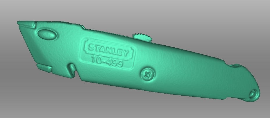
The main assembly scan
Once that scan is complete, we can proceed with disassembly and scanning individual parts. Staying organized and naming each scan as you go will pay off in efficiency later.
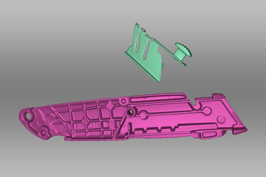
Individual component scans in the initial non-aligned state
Once all the parts have been scanned in, we ‘ll need to align all the component scans with the main assembly scan.
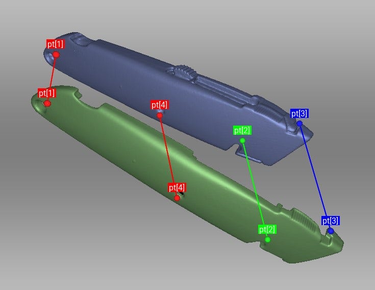
Aligning a component to the main assembly scan using the point-to-point alignment method
Tips for alignment: Depending on the noise level, it may be easier to run global registration and outlier removal on each component scan or group of scans individually before aligning them to the main assembly scan. This is because details and features will be easier to see once those operations are run. This is especially helpful with small parts.
Switching the display mode to points can also help mitigate the visible noise and make alignment easier.
Alignment is typically done manually by using the point-to-point alignment method, as the auto-align feature will produce mixed results with assemblies.
If you have multiple scans from the same part that are already aligned with each other, you can use the shift and/or control key to select and align multiple scans at once.
Dealing with Alignment Failures
When aligning internal components to a scan of the exterior, you may experience occasional misalignments. In the example below, only a small part (the thumb grip) of the carriage is visible in the assembled state.
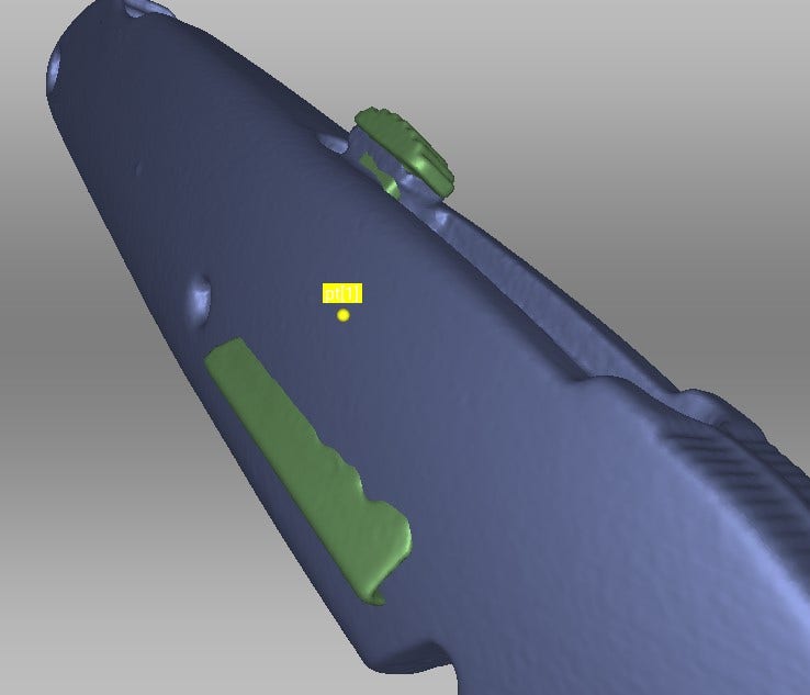
This alignment has failed because the only area the two scans have in common is too small to compute properly
Since the visible area they have in common is very small, the larger area can sometimes “overpower” the smaller one and create an erroneous result. This can be dealt with by creating a duplicate of the component scan, and erasing everything but the visible common area. With the conflicting area gone, the partial duplicate scan should now align more easily to the main assembly.
With the partial duplicate scan properly aligned with the main body, you should be able to align the remaining component scans to the partial duplicate scan without trouble.
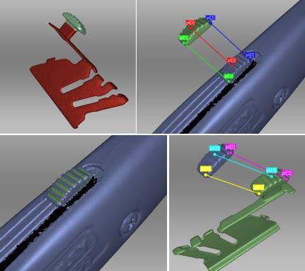
From left to right: erasing the conflicting area, aligning the partial scan to the assembly scan, then aligning the complete component scan with the partial version
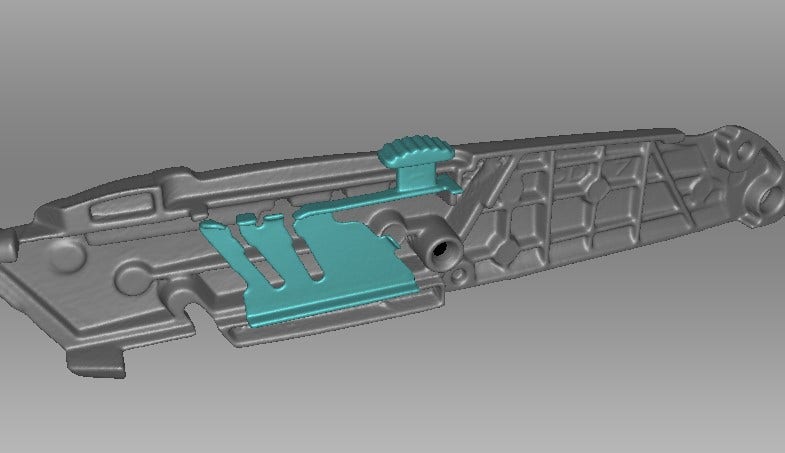
The carriage successfully aligned to the main body
Final Post-Processing
With everything aligned in its proper place, we can accept the alignment and finish our post processing.
We’ll need to run a global registration on each component scan (or group of scans) and then we can run fusions of each individual body (by showing only the scans belonging to a single component at a time).
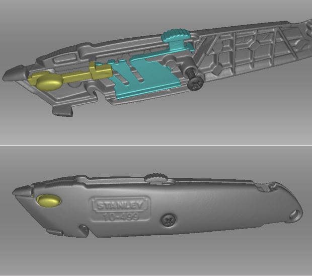
The assembly scan is complete. Individual fusions can now be hidden at will and exported as separate bodies in their relative positions.
For more information on Artec 3D Scanners or if you have any questions, contact us at Hawk Ridge Systems today. Thanks for reading!