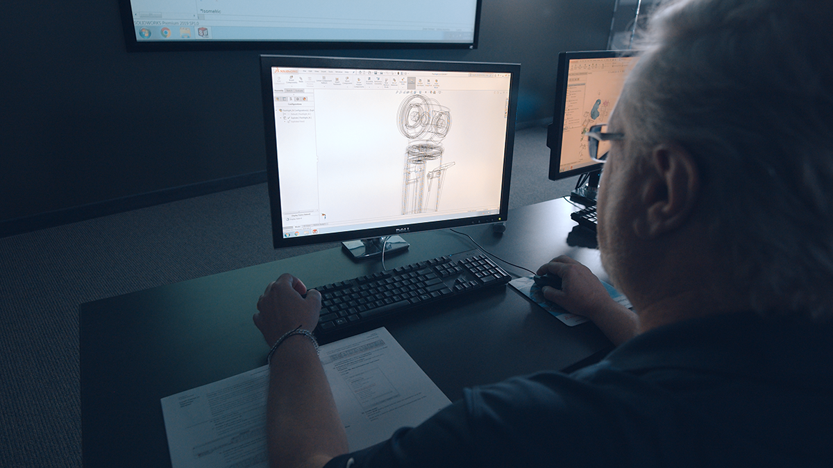
For some projects, it’s important to fully define your sketches in 3D CAD programs because it helps reduce errors and ensures the geometry stays the same. There are some great arguments for when to use and when not to. In General, Fully Define Sketch in SOLIDWORKS is a handy way to fully dimension your sketch. When modeling in SOLIDWORKS, it’s nearly always best practice to fully define sketches before moving to the next step or feature of the model. For example, sketches for rib features can typically be left under-defined, as well as temporary sketches used for quick tests.
While sketches can be fully defined manually and in a variety of ways, the Fully Define Sketch tool can be used to quickly add many dimensions and/or relations to a sketch at once to fully define it.
Know When to Use Fully Define Sketch vs. When to Dimension Manually
While the decision ultimately rests with each user and his or her preference and sometimes the type of design you are working on, two things should be kept in mind when deciding whether to use the Fully Define Sketch tool or to dimension manually:
- Consider how many dimensions or relations need to be added to a sketch.
- Consider how close the Fully Define Sketch tool will get to the desired result.
Typically, as the number of dimensions or relations increases, especially if they are repetitive, it becomes more advantageous to use the Fully Define Sketch tool.
Additionally, the geometry of the sketch will determine how close the Fully Define Sketch tool gets to the desired result. If the sketch contains more complex geometry like arcs, splines, and ellipses, or requires relations like equal or midpoint, it is typically better to define these items first before running the tool. If the sketch contains lines and points, and relies on relations like horizontal/vertical, parallel/perpendicular, and coincident, it will be more suited to the Fully Define Sketch tool.
4 Useful Examples of Sketches when Using Fully Define Sketch
Here are some example sketches showing what to look for when determining if the Fully Define Sketch command will work well.
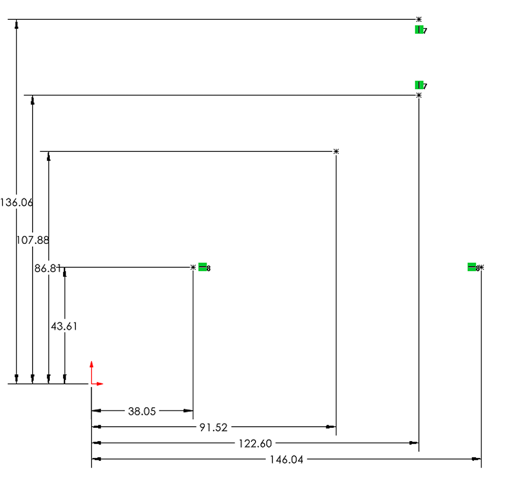
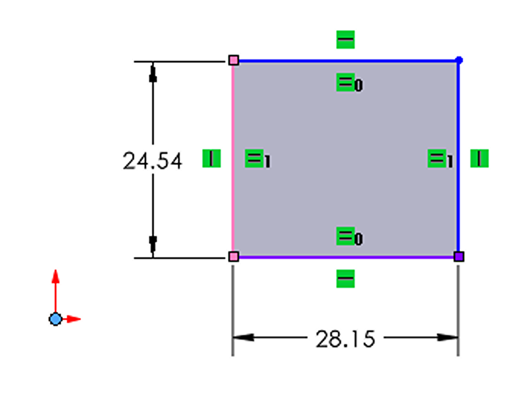
Example #1: Use Fully Define Sketch with a Grid of Lines
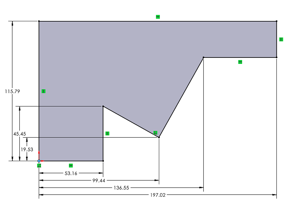
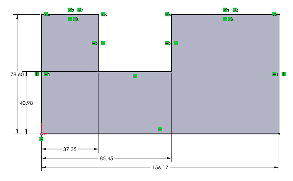
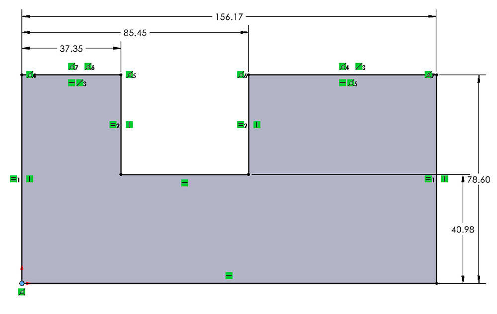
Example #2: Use Fully Define Sketch with a Single Closed Contour of Lines
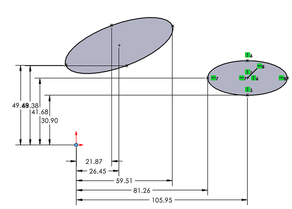
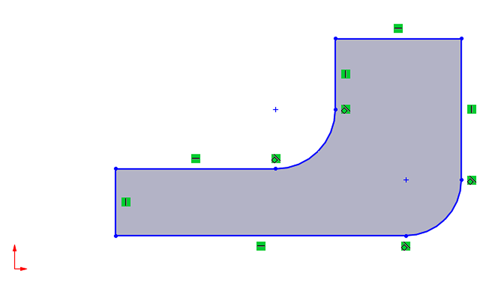
Example #3: Avoid Ellipses with Fully Define Sketch
Example #4: Use Fully Define Sketch in Combination with Manually Defining Relation
How to use Fully Define Sketch in SOLIDWORKS
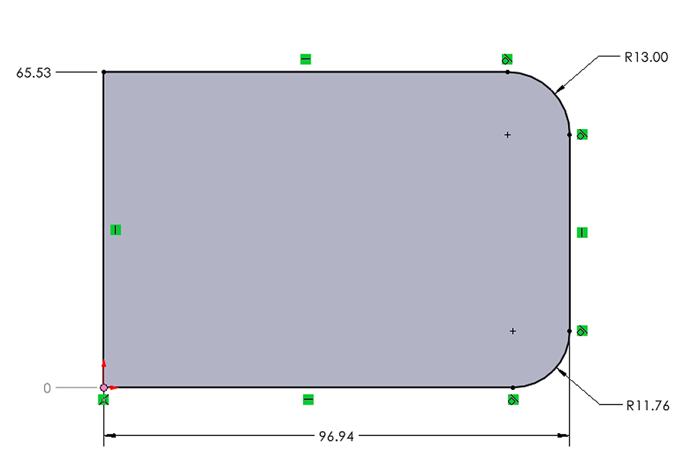
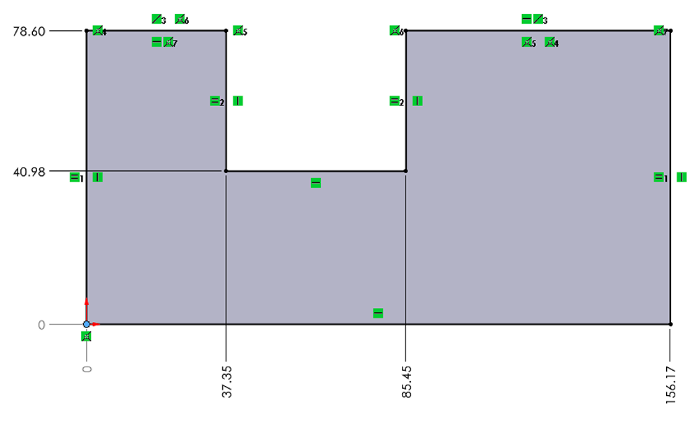
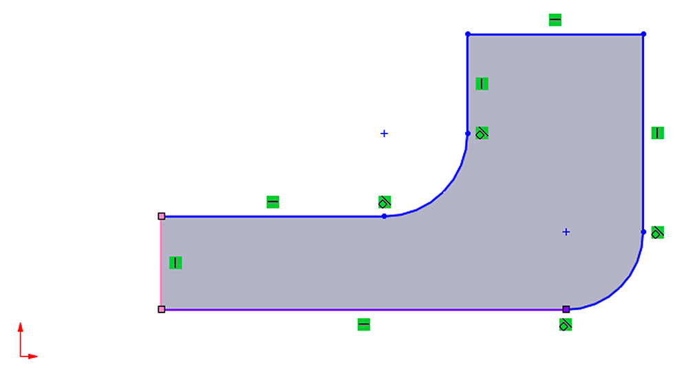
Below, the Fully Define Sketch PropertyManager will be covered, where all the different settings of the tool can be adjusted. The sketch below will be the example used in this section.
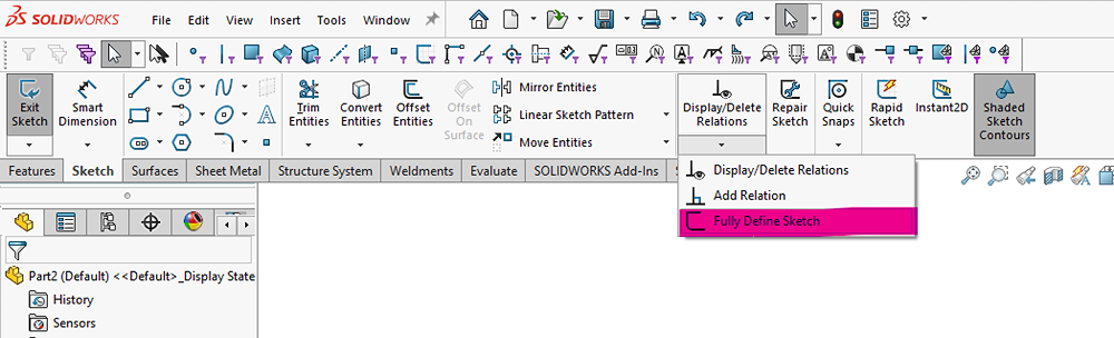
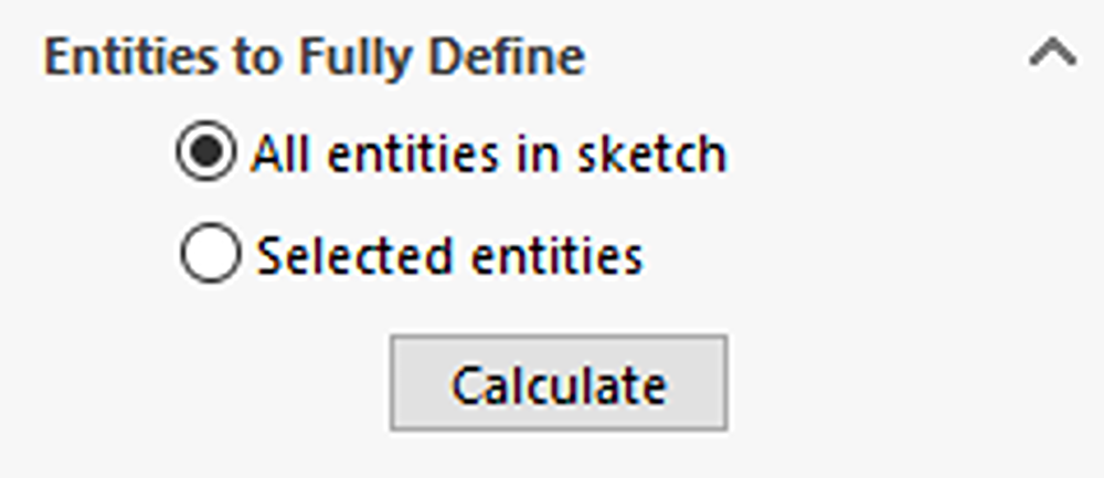
Select Which Entities to Fully Define
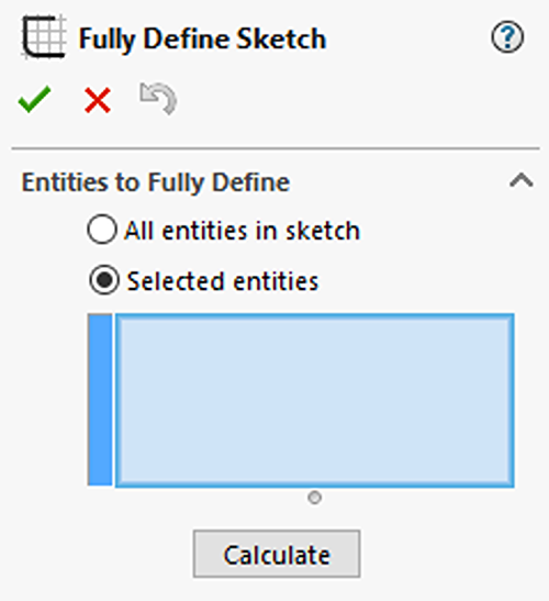
The first section of the PropertyManager controls which entities the tool has access to: either all entities or only selected entities. Use selected entities if you want to manually define parts of your sketch after running the tool. Use all entities if you want to fully define the sketch and any manual dimensions or relations (if necessary) have already been added.
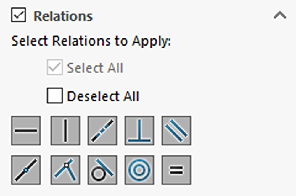
Relations

The second section of the PropertyManager controls which relations the tool may add to the sketch. Selecting these relations only makes them available for the tool to use in its calculation but does not guarantee it will use all of them or even any of them. Checkboxes exist to quickly select or deselect all available relations, or individual relations can be clicked to toggle them on or off.
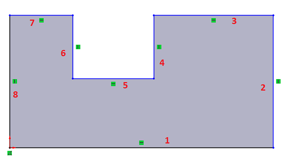
In the example sketch, because the top lines 3 and 7 are aligned with each other, a collinear relation will be added by the Fully Define Sketch tool if the relation is enabled. See the example images below.
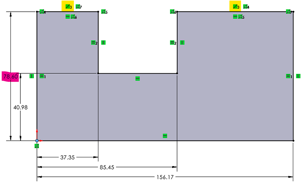
Note that relations will only be added by the Fully Define Sketch tool if the entities are already in the proper position. In this example the lines were already collinear (because of their initial snapping with inference lines), so a collinear relation could be added. These alignments can be achieved by using the blue inference lines to snap sketch geometry to the proper position while sketching.
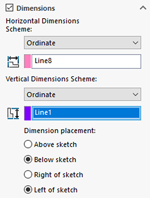
Dimensions
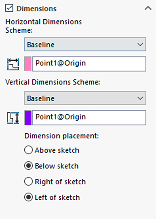
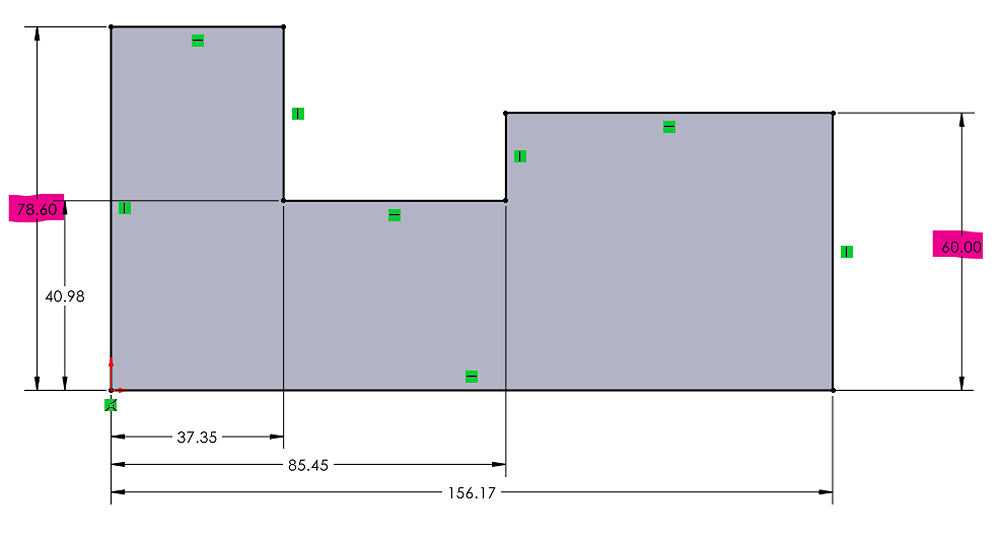
Last is the dimension section. The scheme can be selected in the horizontal and vertical directions as either chain, baseline, or ordinate. See the pictures below for examples of each scheme.
Chain Dimensioning Scheme
Baseline Dimensioning Scheme
Ordinate Dimensioning Scheme
Datums when Using Fully Define Sketch
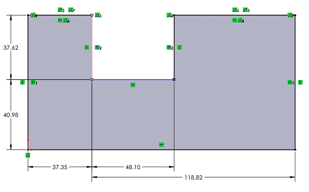
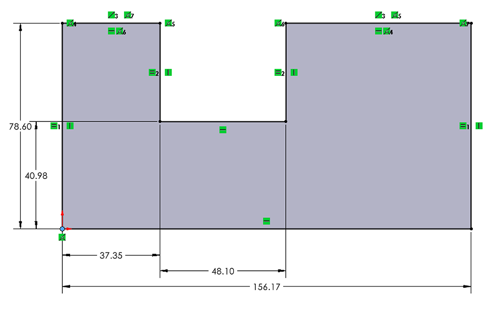
The datums control where the horizontal and vertical dimensions are measured from. They can be either internal to the sketch (a point or line in the sketch), or external to the sketch (the origin, or a model edge or vertex). When using a datum attached internal to the sketch, the size and shape of the sketch can still be fully defined, but its position relative to the part origin may not be defined. See the example sketch below.
Dimension Placement when Using Fully Define Sketch
Example Walkthrough of Using Fully Define Sketch
- Create a sketch, making use of inference lines to capture any basic relations (horizontal, vertical, perpendicular, parallel)
2. Choose “All entities in sketch”
3. Enable all relations
4. Choose the desired dimension scheme (Ordinate, in this case)
5. Change the datum, if desired. For this example, the datum will be changed to the lower left corner of the sketch.
6. Click the “Calculate” button to preview the results.
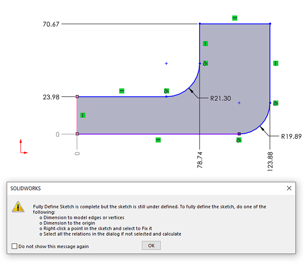
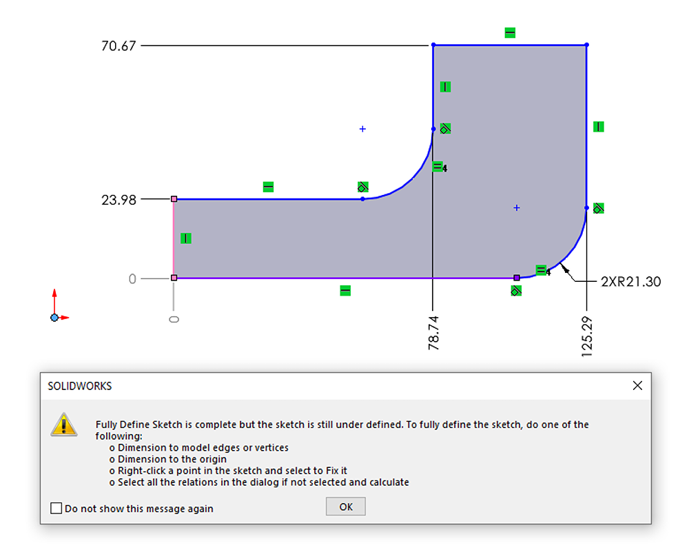
7. Evaluate the results. In this example there are two problems: First, the sketch is still under-defined because it has no dimensions controlling its position relative to the origin, and second, the two arcs are dimensioned separately while the design intent calls for them to be equal. From here there are three options at the top of the PropertyManager. (Just above the Entities to Fully Define section)
-
- Green check: Accept the results as-is and insert them into the sketch
- Red X: Discard the added dimensions and relations and go back to editing the sketch manually
- Blue arrow: Discard the added dimensions and relations and go back to the PropertyManager to adjust any settings which may give a better result (e.g. changing datums, enabling/disabling relations)
8. For this example, we will discard using the red X and go back to manually editing the sketch.
9. Manually add an equal relation between the two arcs.
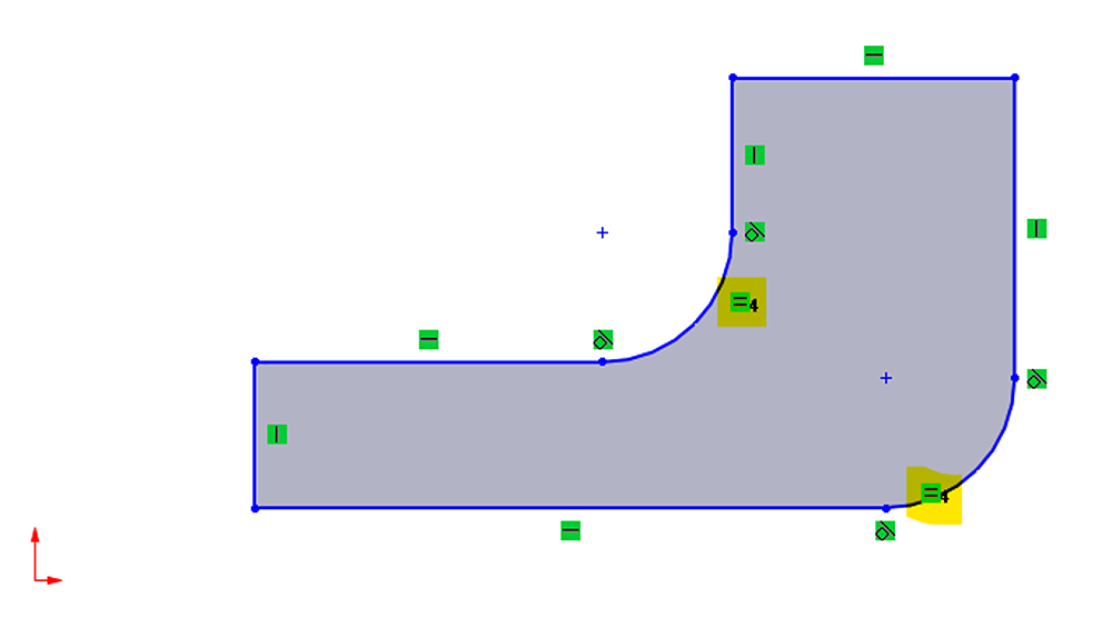
10. Rerun the Fully Define Sketch tool. The radii are now controlled by a single dimension, but the sketch is still under-defined because there is no relation or dimension to the origin.
11. Green check to accept the results as-is.
12. Manually add dimensions to position the sketch relative to the origin and fully define it.
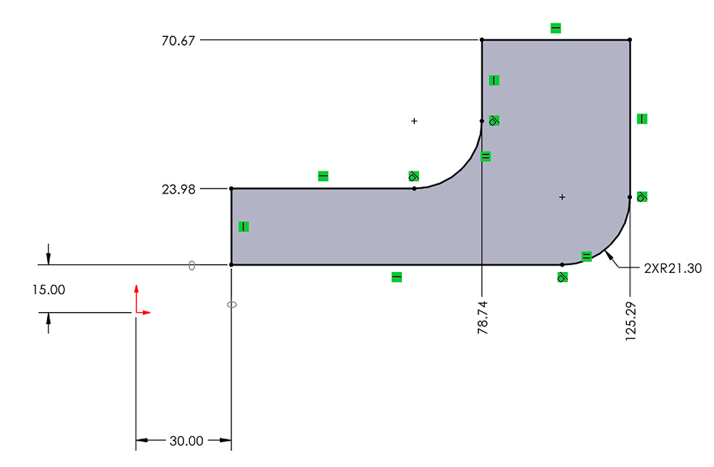
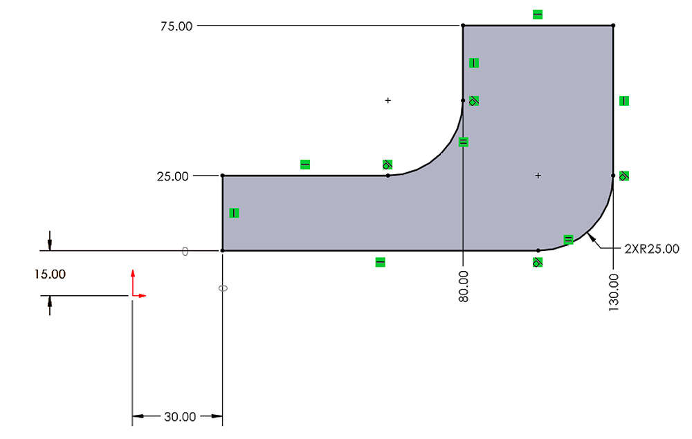
13. Adjust any remaining dimensions to their final values by double clicking each one and inputting the desired value
Common Pitfalls
After completing the Fully Define Sketch command with the green check, the only way to revert is to use undo (Ctrl-Z). Make sure you do not continue working unless you are satisfied with the results of the tool (e.g. adding more dimensions, relations, sketching) as any work you do after the tool will need to be undone if you decide you want to undo the actions of the Fully Define Sketch tool.
A workaround (which is nearly as quick) to this is to manually delete the dimensions and/or relations added by the tool instead of using undo.
Final Thoughts on Fully Define Sketch
The Fully Define Sketch tool is very powerful and can be used to save both time and effort when working in SOLIDWORKS. However, like most tools, knowledge of when it’s best applied is as important as simply how to use the tool. Based on the examples shown here, you should be able to develop your understanding of the tool and determine at a glance which of your sketches are best suited to the tool and which sketches should be manually defined.
If you have any questions about this tool or other time-saving tips in SOLIDWORKS, contact us today.