Creating drawings is a key part of the design process. With SOLIDWORKS Drawings, documenting your designs so that you can communicate those designs to other people is a cinch. But sometimes when creating drawings, the default drawing scale may not work for your desired intent.
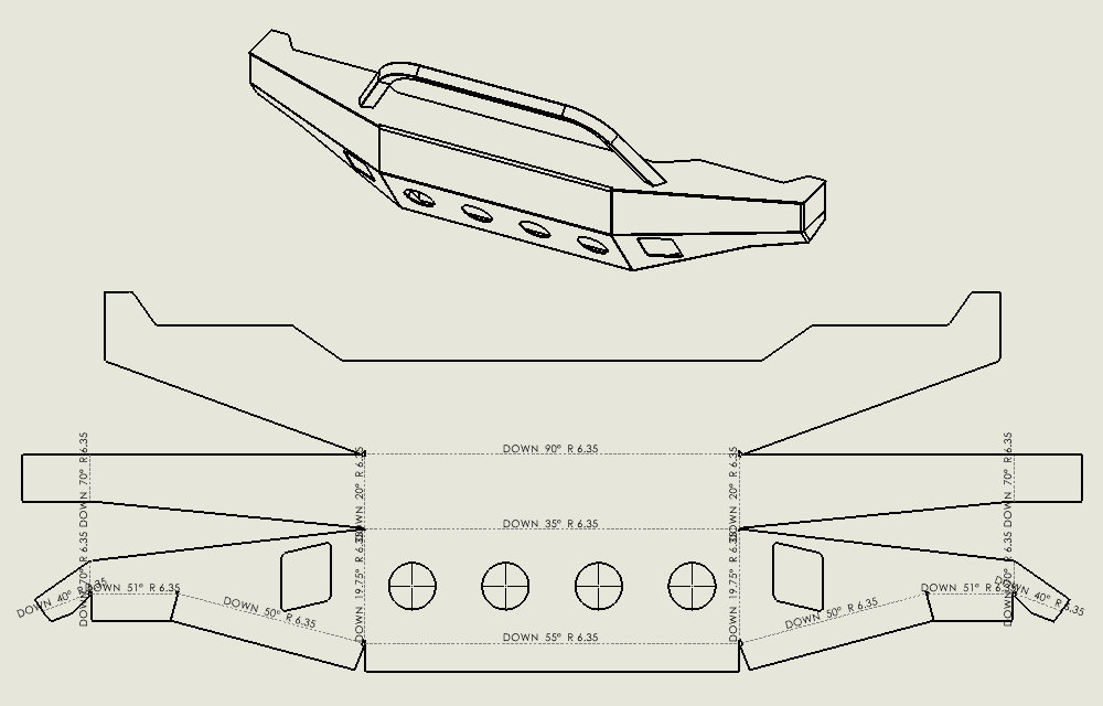
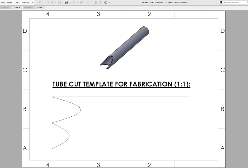
This might be the case if you have a product or design that is very large in one dimension but very small in another. Or if you are using display states to only show certain components of a much larger assembly. Another case is if you need an exact 1:1 scale when printed onto a physical piece of paper. A true 1:1 scale is important if you want to use the printed drawing as a template for manual sheet metal or tubing cuts or if you want your drawing to match DXF/DWG exports.
The Basics: Changing the Scale of Drawing Sheet
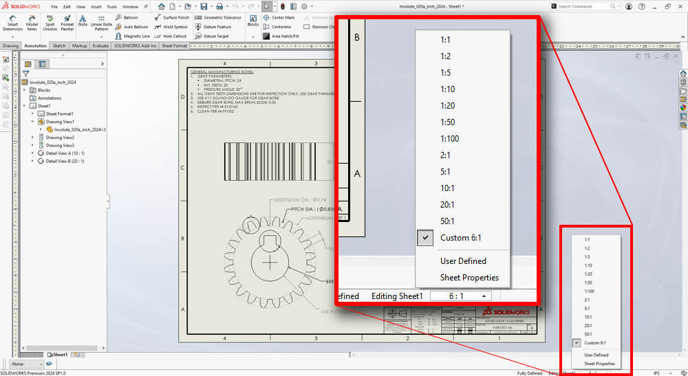
Changing the scale of a drawing sheet is a straightforward process. In any drawing document, at the bottom right of the SOLIDWORKS interface, there is a quick select menu for sheet scale. This quick select menu gives you a handful of standard options for sheet scale such as 1:1, 1:2, 4:1, and so on. You can also enter custom values, if necessary. This method allows you to change the scale for an entire sheet with just two clicks.
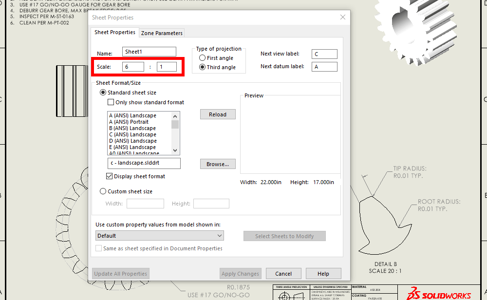
You can also change the sheet scale through the Sheet Properties dialog. To access this dialog, right-click on your drawing sheet and select “Properties”.
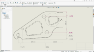
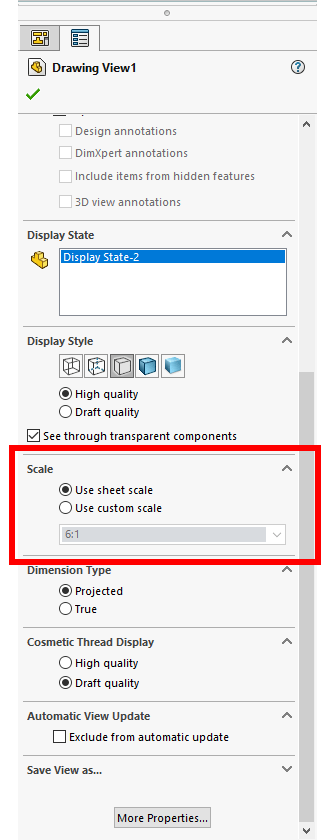
The scale of individual drawing views can also be modified via the PropertyManager. This applies to standard drawing views, detail views, section views, or nearly any other type of view. You can navigate to the “Scale” section of the PropertyManager to select the scale you need. Just like the overall sheet scale, you can enter it manually for custom scales as well. You can also set them back to use the scale of the sheet itself if you later determine that you don’t need a different scale for that specific view.
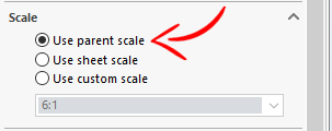
For child views, such as detail or section views, you also have options to relate the scale back to the scale of the parent view, if necessary.
1:1 Sheet Scale vs. 1:1 Print Scale: Matching a DXF/DWG Export
Sometimes there are cases where you need your printed drawings to be precisely a 1:1 scale with your physical parts. This can be useful for quickly mocking up designs that are part of a larger assembly or if you want a guide for fabrication or conceptual design work.
A 1:1 printed scale can also be useful for preliminary part verification during manufacture when validating machining setups or CNC programs. It can also be beneficial when you want your drawings to match a 1:1 DXF/DWG export (more on that later).
Drawing Settings in SOLIDWORKS
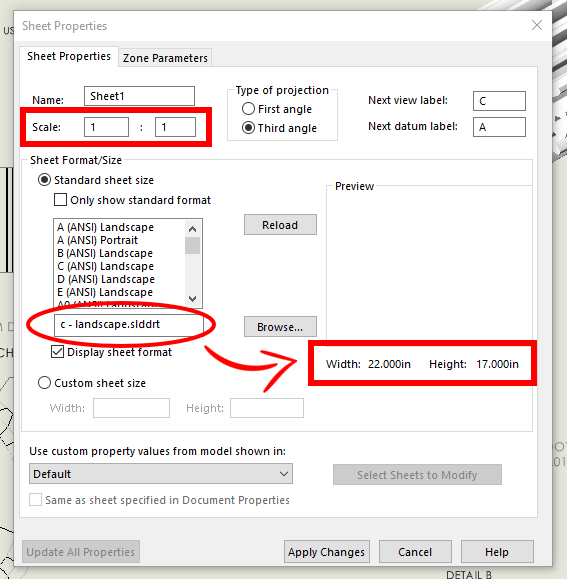
Setting your sheet or view scale to 1:1 in your SOLIDWORKS drawing does not always guarantee that your views will remain 1:1 when printed. The first step is to set your desired sheet or drawing views to 1:1 in SOLIDWORKS. You should also ensure that your sheet size in SOLIDWORKS matches the actual paper size you will be printing on. It is possible to still print 1:1 without having your sheet size match your paper size, but it can result in parts of your drawing being unnecessarily cropped.
Printer Settings for Drawings in SOLIDWORKS
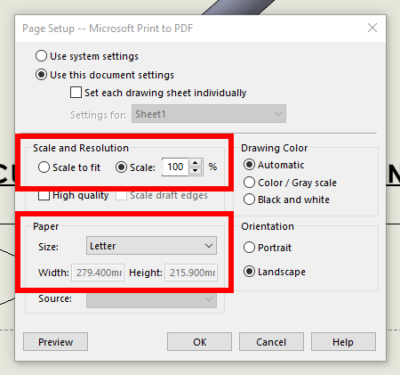
In addition to your drawing settings, you also need to double-check the printer settings. In the “Page Setup” dialog of your print settings, the easiest way to ensure that your drawing prints 1:1 is to ensure that the “Scale:” is set to 100%. Additionally, make sure your paper “Size:” correctly matches the sheet size. You can select the “Preview” button at the bottom of the dialog to ensure everything is correct and you won’t get any unexpected scaling or cropping.
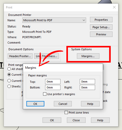
You should check that the paper margins in the “Print” dialog are set to 0 (zero) so that your printer doesn’t automatically scale your drawing when printing by adding margins on the physical print.
With these settings, the drawings should now print 1:1!
Note that if you have the need for an extremely accurate print, a plotter or technical printer is likely going to be your best bet (especially if you have a very large model!). That being said, most modern printers are perfectly suitable for most 1:1 prints.
Additional Printer Considerations
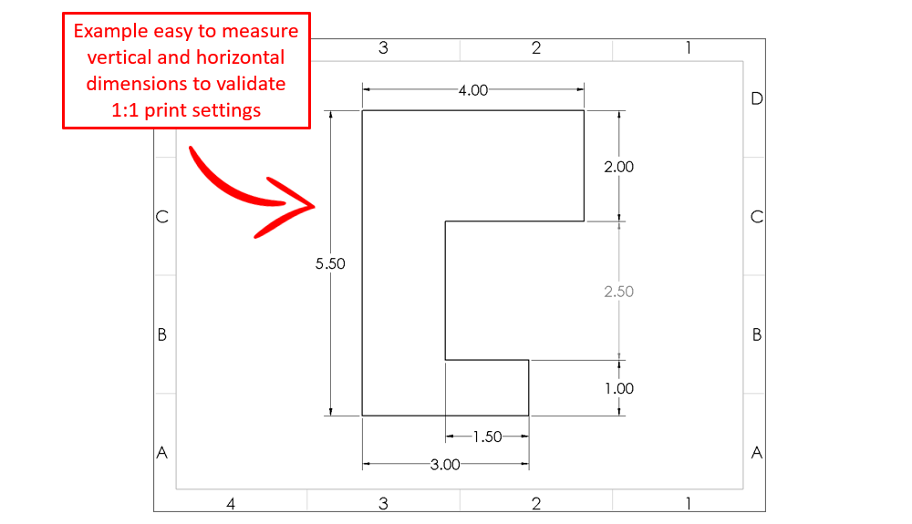
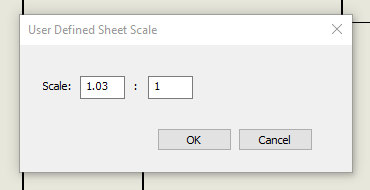
There can be cases where certain printers do not accurately respect the settings we’ve discussed above. Certain printer models can artificially scale drawings down simply due to the printer’s firmware and/or drivers. Therefore, in general, you should verify that your prints are actually 1:1 when printing your first 1:1 document. Typically, that can be done by printing a 1:1 drawing of a simple, easy-to-measure (on the physical print) model. That way you can quickly check with a set of calipers whether your printer is giving you your desired result. In cases where it doesn’t, you may have to do some extra tweaking on the sheet or drawing view scales to account for this (e.g., setting the scale to 1.03:1 to account for a ~3% printed scaling).
Sheet Scale and DXF/DWG Exports
A true 1:1 scale is also useful for DXF/DWG exports. This might be for use in another program or as an input to a machine such as a waterjet or laser cutter. When exporting geometry, such as the flat pattern of a sheet metal part, the output is automatically 1:1. All you need to do is right-click your part, select “Export DXF/DWG” and then export the file as normal.
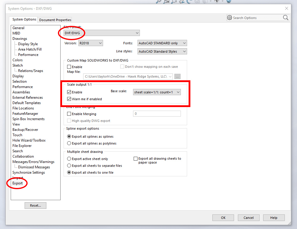
When it comes to exporting drawings to DXF/DWG format, the process is also straightforward, but there are additional settings to consider. This is because a single drawing can have many views of many different scales. In the settings for “DXF/DWG” under the “Export” section of System Options, there is a setting called “Scale Output 1:1” which helps control this.
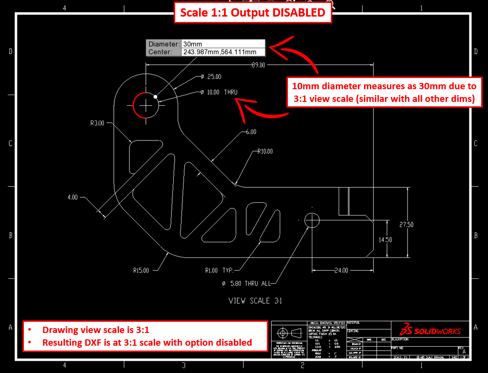
If this option is disabled, any views that are not scaled to 1:1 will appear exaggerated in the DXF/DWG relative to their scale in SOLIDWORKS. So, for example, if you have a drawing with a sheet/view scale of 3:1, a 10mm diameter will measure 30mm when exported as a DXF/DWG. In this case, if you want to ensure your DXF/DWG exports are at a 1:1 scale, you have to ensure each drawing view is at a 1:1 scale prior to export.
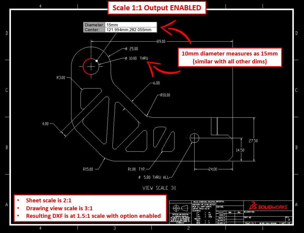
If the “Scale Output 1:1” is enabled, you can tell SOLIDWORKS to choose a base scale in the DXF/DWG export options to scale all drawing views by. For example, if you have a drawing with a sheet scale of 2:1 with a drawing view with a 3:1 scale, choosing the sheet scale as the base scale will output that specific drawing view at a 1.5:1 (3:2) scale in the DXF/DWG export.
Learn even more about DXF/DWG exports or watch our tutorial about print scale drawing.
Also, remember to consider how units are treated when using DXF/DWG in SOLIDWORKS or other programs. We created a handy guide on how to import correct units when working with DXF/DWG and also a post on how to import DWG files into SOLIDWORKS.
Sheet Scale using DraftSight for our DXF/DWG Exports
If additional control is needed for DXF/DWG exports, an excellent option is to use DraftSight. While SOLIDWORKS has tools for working with DXF/DWG files, DraftSight is a dedicated 2D drafting tool. DXF/DWGs are DraftSight’s bread and butter. A high level of control over scaling, editing, creating blocks, mapping layers, creating lists for commonly used scales, etc. Is available when using DraftSight.
If 2D CAD modeling better fits your application or if you need a powerful, dedicated DXF/DWG editor that’s integrated with SOLIDWORKS, PDM, and cloud-based data management, it’s likely that DraftSight will be a perfect fit.
To learn more about DraftSight and its capabilities, be sure to check out our post on Modern Use Cases for 2D CAD and our article that weighs DraftSight versus AutoCAD.
More Information on Sheet Scale in SOLIDWORKS
There are many ways to set and adjust the scale of drawing sheets and individual drawing views. SOLIDWORKS makes it easy to get the exact scale needed to correctly detail drawings, whether it be creating 1:1 prints, accurately scaling our DXF/DWG exports, or simply modifying drawing views to correctly capture your designs. And if you routinely work with DXF/DWG files and exports, DraftSight offers a dedicated set of tools to do just that.
If you’re looking at getting deeper subject knowledge on SOLIDWORKS Drawings, check out our SOLIDWORKS Drawings course.
If you have any further questions, don’t hesitate to reach out! As always, we are here to help be part of the solution to your design and engineering challenges. Contact us at Hawk Ridge Systems to discuss how the suite of SOLIDWORKS software can help improve your workflows and product lines.