
Facility Layout is a powerful assembly technique that can be used in SOLIDWORKS to help streamline the arrangement of machinery or equipment on a factory floor. When you’re working with very large models such as plant layouts, the special tools and workflows in Facility Layout are invaluable. Large models can slow down your workflow, so everything you can do to optimize performance is also important.
To use Facility Layout, there are two important stages to consider.
First, normal SOLIDWORKS models (these can be parts or assemblies that represent the machinery or equipment) must be turned into assets. Once assets have been made, they can be inserted into the facility assembly. This blog will cover the first stage of creating assets and the next blog will cover the insertion of assets into a facility.
Asset Publisher in SOLIDWORKS Facility Layout
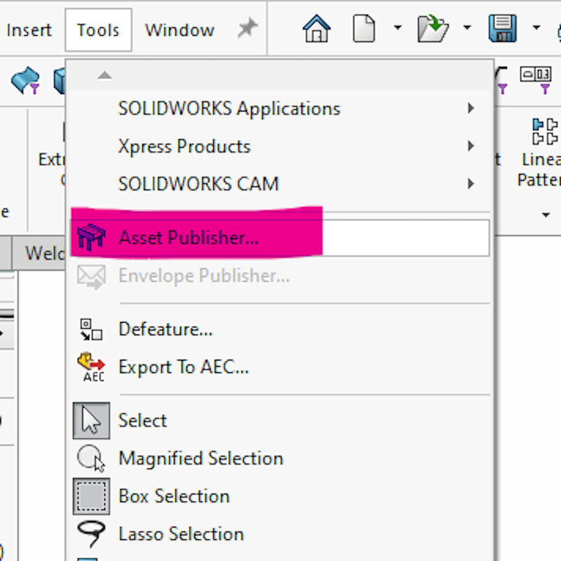
An asset is simply a component with a Published Reference feature. The purpose of the published reference feature is to help locate the component inside the facility assembly. To create an asset, first open a part or assembly. Then go to Asset Publisher, which is located under Tools > Asset Publisher. It’s near the very top of this menu. The Asset Publisher PropertyManager will open.
Defining the Ground Plane of the Asset
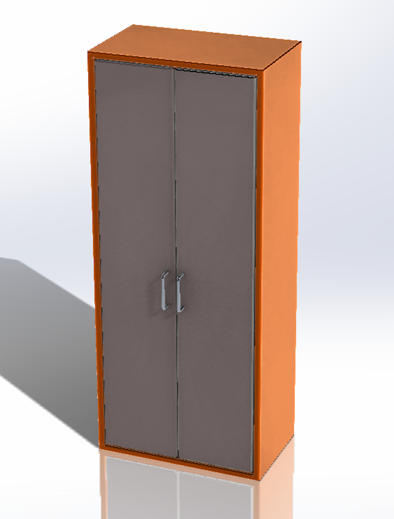
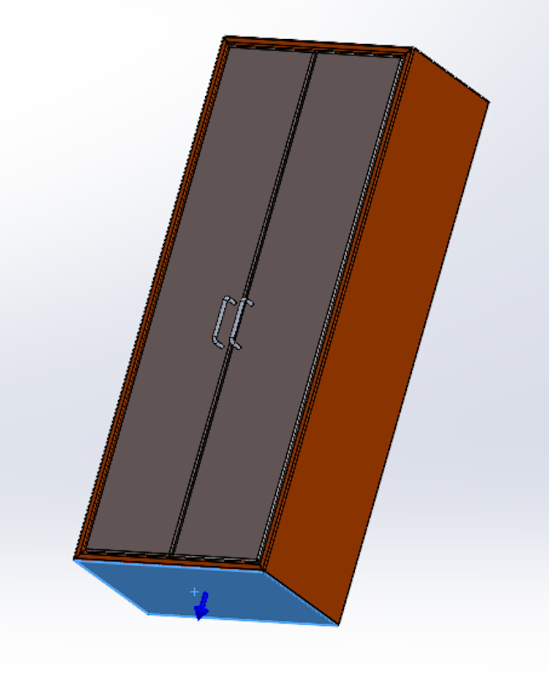
First, the ground plane of the asset needs to be defined. This can be a plane or a planar face. The ground plane represents where the asset will sit relative to the floor of the facility. While the example shown here will sit on the floor, assets can be designed to attach to the walls or ceiling of a facility as well. In those cases, the “ground” plane would be a face on the side or top of the asset instead of the bottom. In the example below, the bottom face of the cabinet is selected for the ground plane. Notice the arrow points outwards.
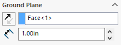
The ground plane can also be offset by a set distance. For this cabinet example, the offset could be used to represent small rubber feet on the bottom, which are omitted from the model for simplicity/efficiency. The offset makes sure the cabinet still sits at the same height above the floor even without the feet being modeled. In this example, we added an offset to raise the cabinet off the ground by one inch to represent small rubber feet.
Connecting Points
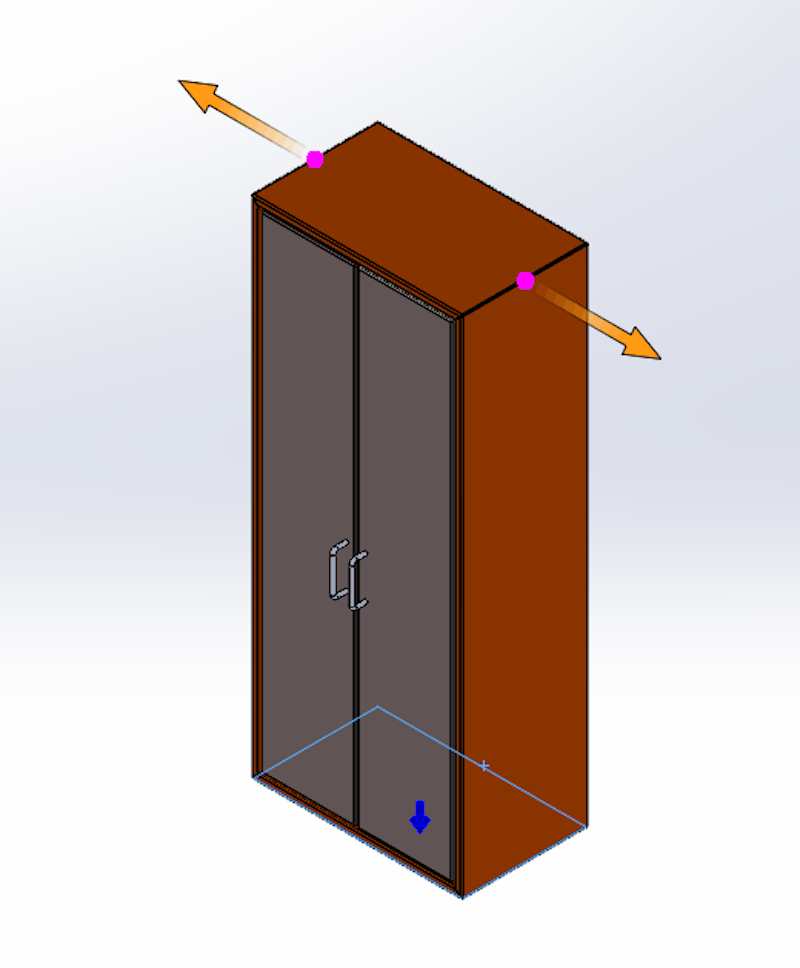
The next thing to consider is the connecting points. An asset does not technically require any connecting points, but it’s typical to make at least one connecting point and often two to four.
Connecting points are used when the asset is inserted into a facility and magnetically snaps adjacent assets together. To define each connecting point, a location needs to be selected. This can be a point, a straight edge, or a circular edge. In this example, we’ll use the straight edge for the location of the connecting point.
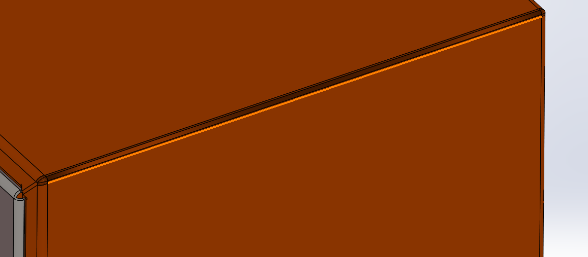
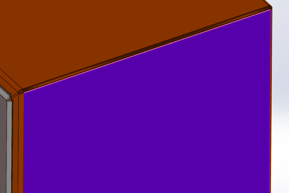
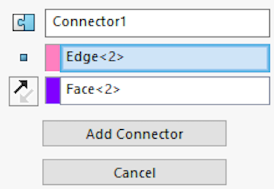
If a straight edge or circular edge is used, the location of the connector will be the midpoint or circle center, respectively. Next, the connector needs a direction reference, to determine how it will orient itself relative to other assets. This is defined with a face selection from the model, where the connector direction will then be normal to the face. Click Add Connector once both selections have been made.
Wrapping Up
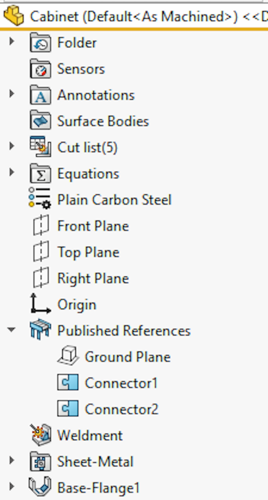
Once the ground plane and any connectors have been set up, the command can be confirmed by clicking the green checkmark. A feature will appear in the tree called “Published References” where the ground plane and connector(s) will be nested under. These can be renamed and if any changes need to be made the feature can be edited by right clicking and choosing “Edit Feature” just like any other feature.
Conclusion
At this point, the model has successfully been turned into an asset and is ready to be inserted into a facility assembly, which is covered in the next blog article. By publishing an asset, two things are done: the model’s ground plane is defined as well as the connectors to adjacent assets of any kind.
To learn more about other solutions for layout planning, check out our guide to virtual factory layout planning.
As always, if you need help with facility layout or have questions, reach out to Hawk Ridge Systems.