Sketches in SOLIDWORKS are like the foundation of a skyscraper – without them, you couldn’t build one! Well-developed sketches are one of the major keys to creating intelligent and flexible models, and we want to introduce you to several sketching tools/techniques and provide you with the understanding you need to start creating your own.
Getting Setup for Sketching
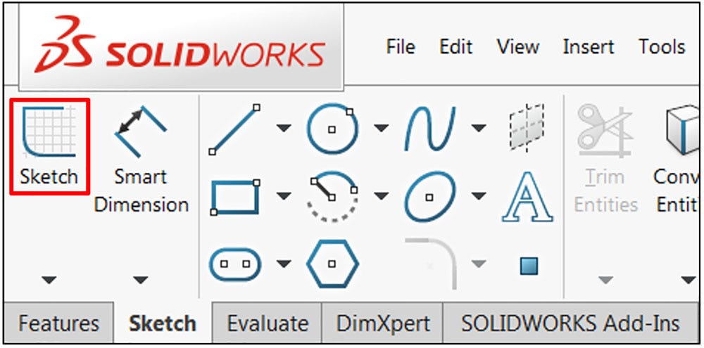
A sketch is almost always the first step in designing a new part. To begin, create a new part and select your desired template. Once the user interface is visible, click the Sketch tab of the CommandManager and select the Sketch icon on the left-hand side.
Remember: You can search for commands in SOLIDWORKS if you do not know where they are. Click the down arrow next to the search bar at the top right of the screen, choose Commands, and then type in the name of the command you’d like to use.
Beginning a Sketch in SOLIDWORKS
Note: Be sure to select the Sketch icon and not the arrow beneath it – clicking the arrow will provide an option to create a 3D sketch, which we are not using here.
Because this is the first sketch in the new part, the system automatically displays the three default planes in the model, which act as the primary sketching surfaces in the model. Once the first sketch has been created, subsequent sketches will not automatically show these planes, although they can still be used.
Additionally, any planar or flat faces of existing geometry can be used as sketching surfaces. To proceed, select one of the planes in the graphics area:
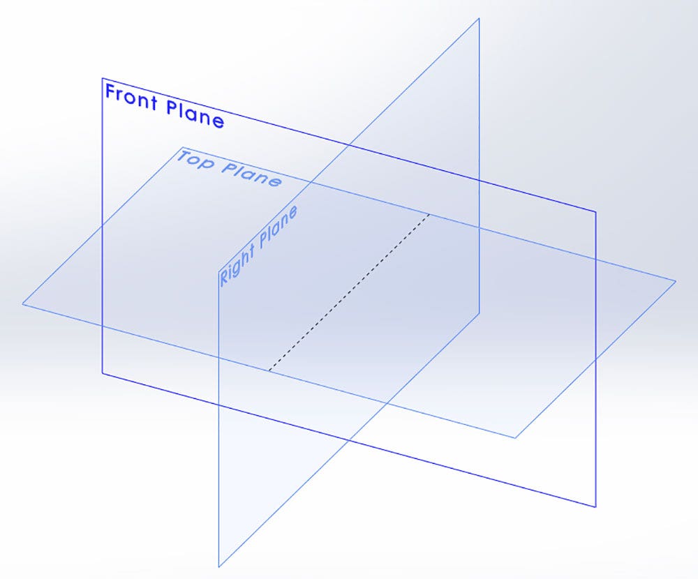
Default Planes Showing after Starting First Sketch
Entering Sketch Mode
Once a plane has been selected, the view orientation will automatically rotate normal to the plane, and you will be entered into sketch mode.
It is important to understand when sketch mode is active, as many other SOLIDWORKS commands will be unavailable in this mode. Likewise, many commands can be executed only when in sketch mode.
Note: Dimensions are one important exception to this rule, as they can be added both within and outside of sketch mode. However, dimensions created outside of sketch mode will not constrain the sketch, and can become very confusing. For this reason, it is important for new users to be certain that sketch mode is active when creating dimensions.
There are several indicators that sketch mode is active. First, you will notice that the Sketch icon we just used has now been replaced with an Exit Sketch icon.
Additionally, you will find that the origin, originally blue in color, is now red.
Finally, in the top right corner of the graphics area, you will see two icons that allow you to save the sketch (blue sketch icon) or cancel any changes (red X icon) and exit the sketch.
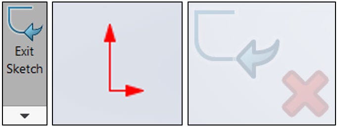
Indicators of Active Sketch Mode
Sketching with the Line Command
At this point, we are ready to begin sketching. On the left-hand side of the Sketch tab of the command manager, you will find several sketching tools that will allow you to construct a variety of basic shapes, including lines, circles and rectangles, among many others. For new users, the Line command is the most basic sketch entity. Click the Line command to begin sketching.
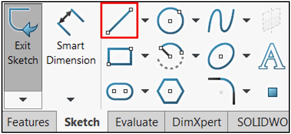
Selecting the Line Command
It is important to make use of the origin, especially in your first sketch, in order to fully define the sketch. Left-click the origin and release to place the first point of the line on it. In doing this, you are creating a Coincident sketch relation between the beginning of the line and the origin, effectively locking it in place.
As you drag the cursor away from the origin, you will see a preview of the line. As you approach a horizontal or vertical orientation, you will notice the line snap into place, and a yellow symbol will appear.
The yellow symbols are very important, as they represent sketch relations that will automatically be added as you create the sketch entities; that is, if the line is created with the horizontal symbol present, that line will be locked in the horizontal orientation from that point forward (although the length may still be adjusted).
These relations can be modified after the sketch has been created, and any that are not captured automatically can always be added.
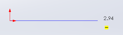
Showing Automatic Horizontal Sketch Relation
Note: The number that appears next to the endpoint of the line represents the length of the line, but does not act as a constraint. The length of the line can still be modified until it is constrained, either by additional sketch relations or dimensions.
When you are satisfied with the length of the line, left-click and release to place the endpoint. As you move the cursor away from the end point once again, you will find a second line is shown, and is automatically attached to the endpoint of the previous line.
(Should you want to end this chain of lines, right-click and choose end chain. Alternatively, the Escape key can be used, although this will end the Line command.) Drag the cursor down and to the right, and when you are satisfied with the position and length, left-click once again.
From here, move the cursor back to the left, ensuring that the third line is horizontal. In addition, be on the lookout for a blue, vertical, and dashed reference line that leads back to the origin.
These lines do not automatically add sketch relations, but are a great visual aid for lining up geometry for easier use. The similar yellow lines pictured below are known as inference lines, and will add automatic sketch relations. Once you see these indicators, left-click to place the third line:
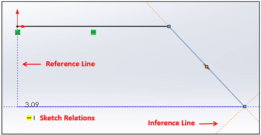
Sketch Geometry and Sketch Visual Feedback
Defining the Sketch
Finally, return the cursor to the origin and left-click to complete the polygon. At this point, the sketch should turn shaded (if using the default options), and we can begin fully defining the sketch. Click the green checkmark in the PropertyManager for the Line command or press the Escape key to exit the tool.
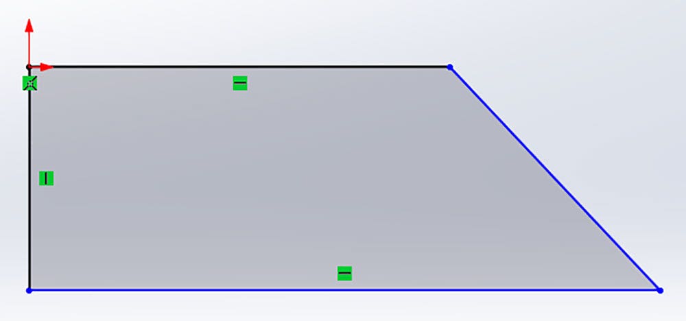
Completed Sketch Geometry, Partially Defined
The green symbols shown in Figure 7 represent the sketch relations we captured during the sketching process, but many others are also available. To reveal these symbols, left-click on a line segment.
Additionally, the blue colors of the lines indicate that these segments are not fully defined, meaning they are still free to move. It is best practice to fully define sketches (with a few exceptions), although it is possible to create features from sketches that are under-defined.
To test the freedom of a sketch, you may click and drag any blue sketch entity or endpoint to see what type of movement is available. This can often help you understand what is required to finish defining a sketch.
Remember, if you mess something up, the Undo command is available in the standard toolbar!
Fully defining a sketch typically requires a combination of both sketch relations and dimensions. To add a sketch relation, click the desired entity, and in the PropertyManager on the left of the interface, you will see the available relations.
In many cases, you will need to select two or more sketch entities to create a relation; hold the control key while making selections to select multiple entities at once. Should you need to delete a sketch relation, click the sketch entity associated with it, right-click the green relation symbol, and choose delete from the shortcut menu. Additionally, the Display/Delete Relations command can be used as well.
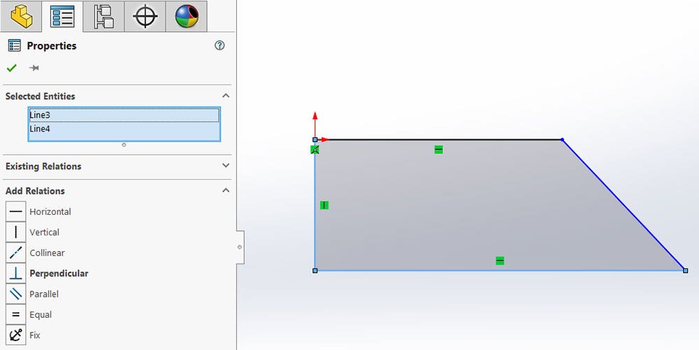
Adding Relations to Sketch Entities
Adding Smart Dimension
No further sketch relations are needed in this design, but in order to size it properly and fully define it, dimensions must be added. To add dimensions, select the Smart Dimension command from the CommandManager, just next to the Sketch icon. Be sure you are still active in the sketch while using this command!
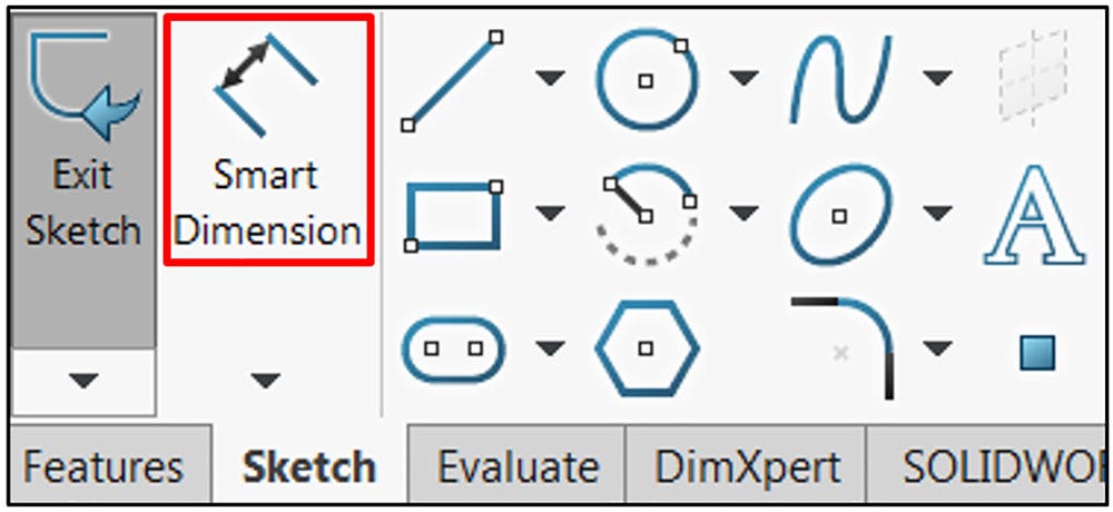
Smart Dimension Command
Once the command is active, begin selecting entities to dimension. These can be line segments, endpoints, arc, or any other sketch entity type. Most dimensions require only one or two selections.
In this example, we will capture the height of the design by dimensioning the vertical line. Click the vertical line.
Once selected, a preview for the dimension will appear – this allows you to continue selecting entities if a different dimension is desired. Since the vertical dimension is what we need, click to place the preview.
A dialog will appear, allowing you to input the dimension value. Type in a suitable value and click the green check mark to complete the dimension:
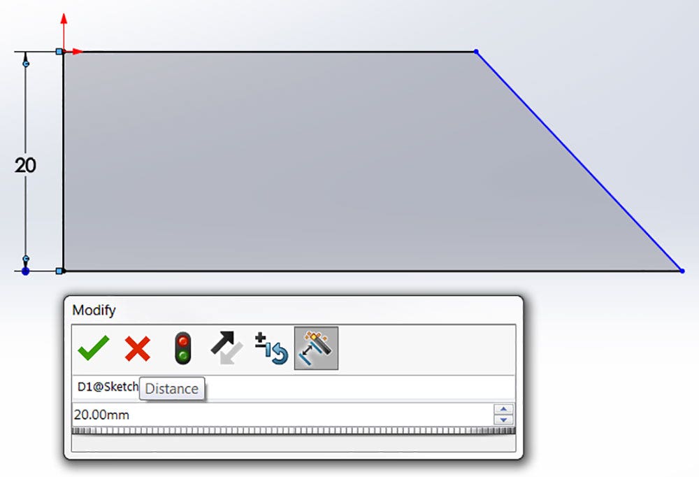
Applying a Smart Dimension and Associated Modify Dialog
Once the dimension has been completed, the Smart Dimension tool remains active. Click the lower horizontal line and place the preview, inputting a suitable value to capture the overall width of the sketch.
Finally, an angular dimension is required to constrain the angled line. This dimension requires two selections; select both the lower horizontal line and the angled line, ignoring the first preview that appears after the first selection.
Place the resulting preview, input a suitable angular value, and confirm the dimension. Due to the intelligence of the Smart Dimension command, different dimension types do not require the use of separate commands!
Note: In many cases, multiple previews will be available when creating a dimension. When this is the case, different values will be shown depending on the location of the cursor on the screen. Be sure to select the preview that is appropriate for the constraint you are trying to apply.
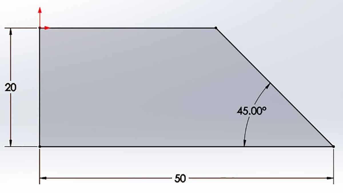
At this point, the sketch should be fully defined, shown by the all-black color of the sketch. If it isn’t, drag any remaining blue sketch entities to determine the available movement, and use that information to apply additional sketch relations or dimensions as needed.
If a dimension needs to be edited, simply double-click the value to bring up the modify dialog, input the new value and confirm.
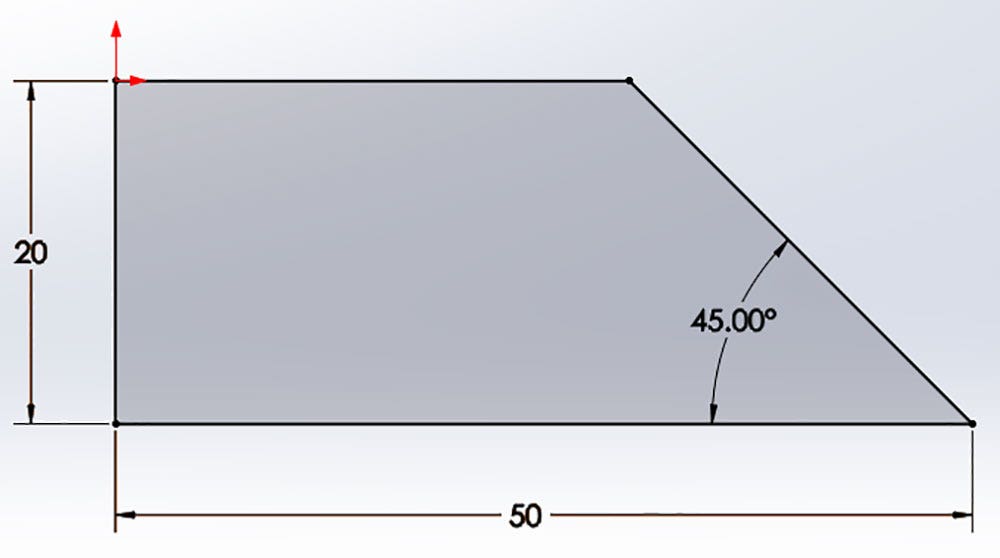
Fully Defined Sketch
Creating the First Feature on Your Part
At this point, we’re ready to create our first feature! Click the blue sketch icon in the confirmation corner (top right of the graphics area) to save the sketch and exit sketch mode.
Then, click the Features tab of the CommandManager. Choose the Extruded Boss/Base icon, and using the default values, click the green checkmark. Congratulations! You’ve officially created your first SOLIDWORKS part.
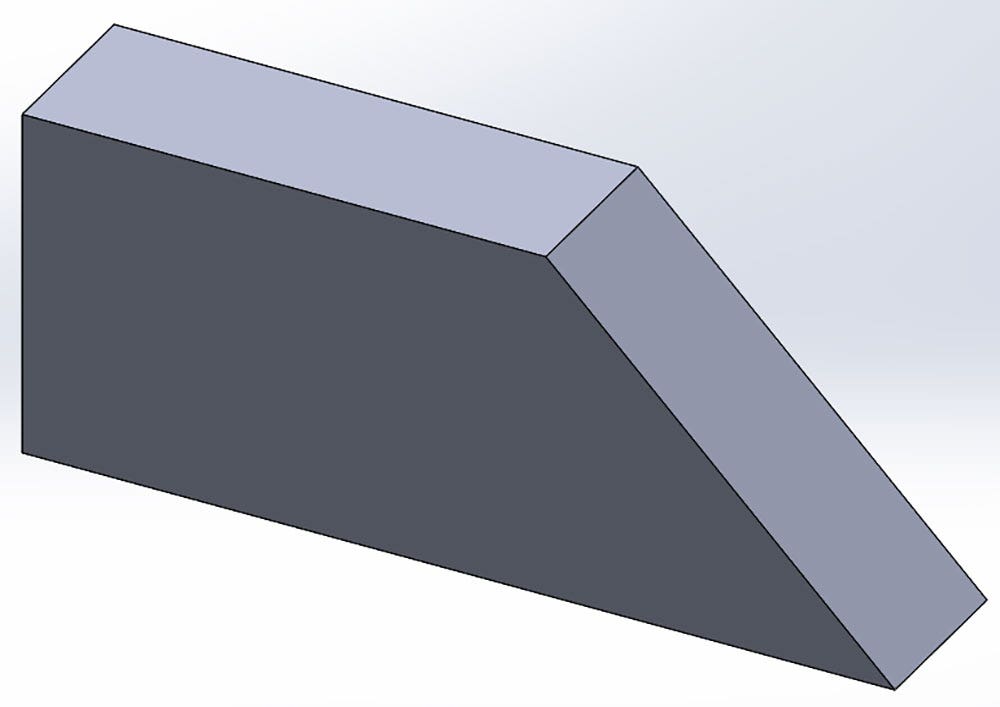
Completed Extruded Boss/Base Feature
Note: If you are presented with a yellow dialog box asking you to select a plane on which to create the feature cross-section when creating the Extruded Boss/Base, don’t panic! Simply select the sketch you created from the graphics area, and it will be used for the feature.
Finally, if you ever accidentally exit your sketch while it’s still in progress, or if you’d like to make some changes to it after it’s complete, you can get back to it by using the Edit Sketch command.
Every sketch and feature created in SOLIDWORKS is stored in the FeatureManager design tree on the left of the screen. If the sketch has not been used in a feature, it should be easy to see in the tree.
Simply right-click the sketch, and choose the first icon in the context menu that appears (the upper menu that shows only symbols):
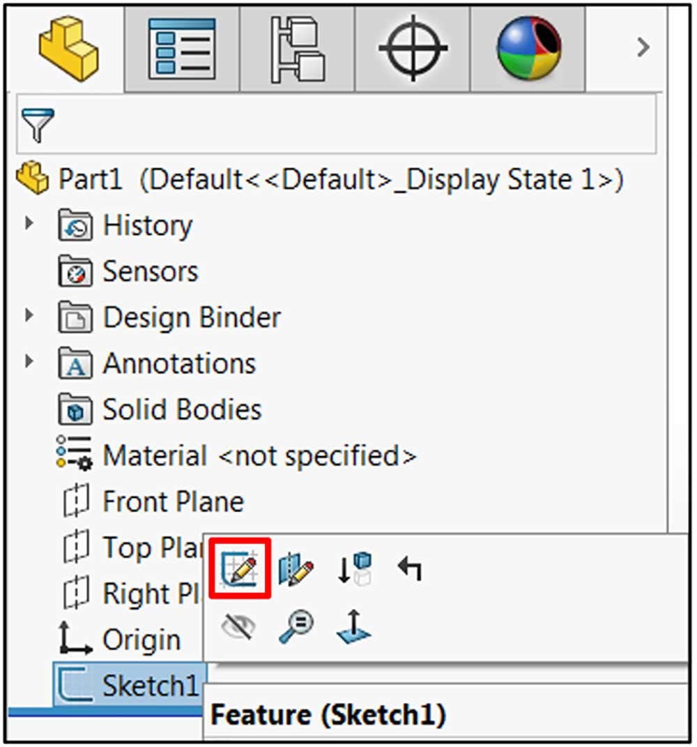
Editing a Standalone Sketch
If, however, you’ve already created a feature from the sketch, the sketch will be nested under the feature and may not be immediately visible.
When this is the case, click the arrow next to the feature to expand it and reveal the sketch. From here, the same steps can be followed. Alternatively, right-click the feature using the sketch, and click the Edit Sketch icon from the context menu (now in the second position):
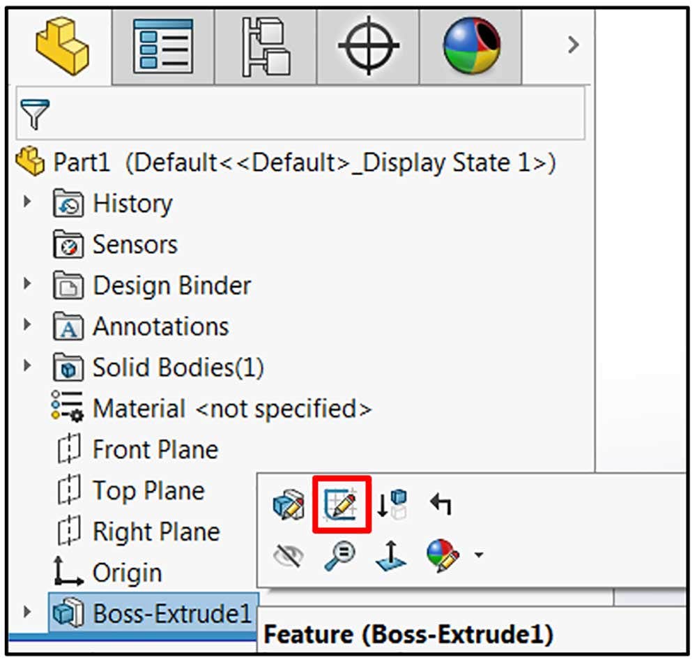
Editing a Nested Sketch
We covered the basics of sketching in SOLIDWORKS to get you up to speed and ready to create your first SOLIDWORKS feature. Visit our website to learn more about SOLIDWORKS CAD, or contact us at Hawk Ridge Systems today. Thanks for reading!


