Have you ever wanted to add additional surface detail or textures to your parts in SOLIDWORKS? Well, SOLIDWORKS has a solution for you with the 3D Texture feature!
There are different reasons why you might want to add a textured surface to our SOLIDWORKS parts—particularly if you plan to 3D print them. Perhaps you are designing a product or component that benefits from tactile feedback to the user, like a button or a switch. Or maybe it’s something designed to be gripped by a human hand and you want to increase useability by increasing grip with a textured surface. Or maybe you want a textured surface purely for aesthetic purposes.
Regardless of the reason, SOLIDWORKS gives us several ways to achieve a textured surface on our parts—the one we are discussing today is the 3D Texture feature.
How the 3D Texture Feature Works
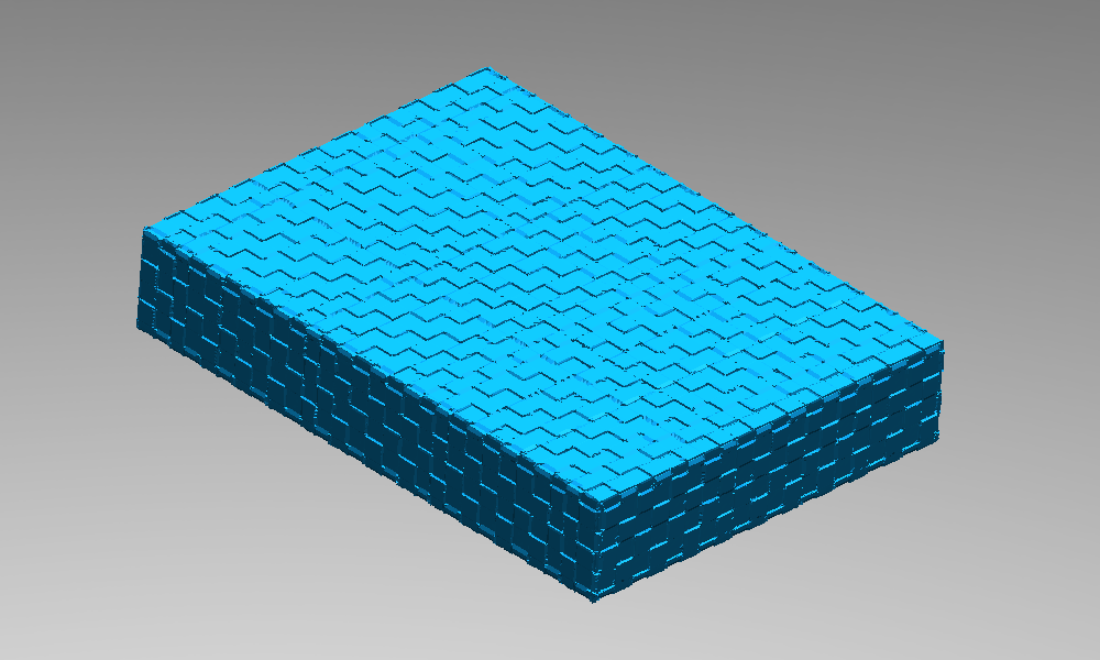
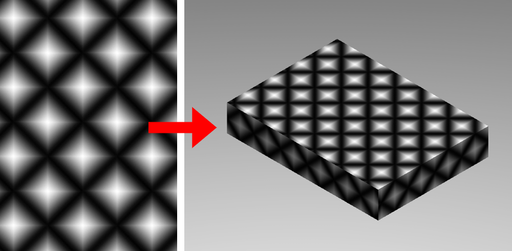
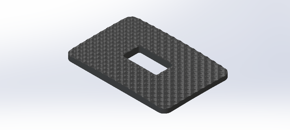
At its core, the 3D Texture feature tool transforms a textural appearance into physical geometry. It takes an existing surface in a model and displaces it using the textural appearance as a heightmap. The amount the surface is displaced is determined by color of the textural appearance—the closer it is to black (or white depending on the setting), the more the geometry is displaced. In this way, the 3D Texture feature allows us to create complex surface geometry from a simple 2D image.
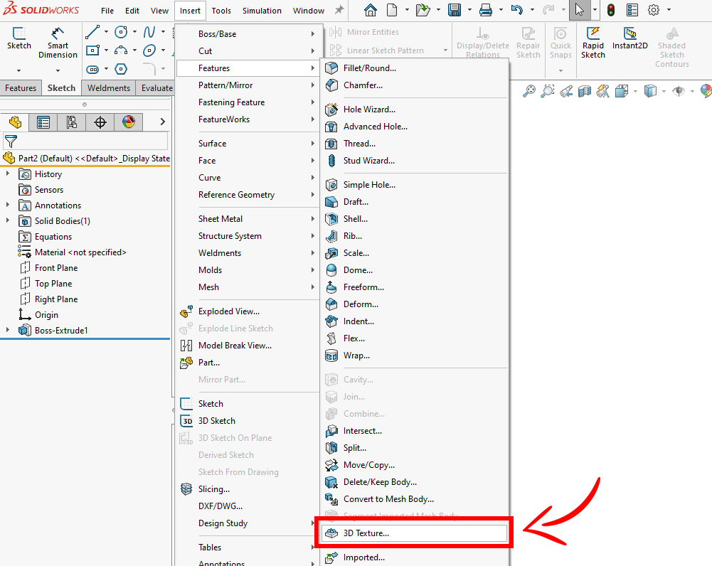
The 3D Texture feature lives in the “Insert” > “Features” drop-down menu.
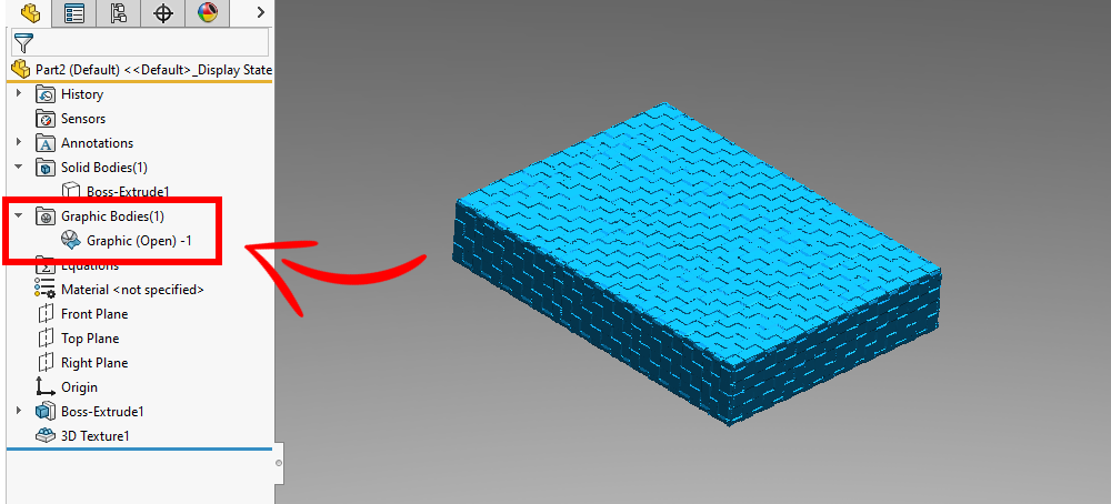
After using the 3D Texture feature, the resulting body is a graphics body. Graphics bodies represent tessellated geometry (made up of triangles) that aren’t editable using traditional means, but can be modified with certain SOLIDWORKS tools. If further model changes are required, hybrid modeling techniques can be used by converting it into a mesh BREP body*. Often a graphics body can be used directly for manufacture and is particularly well suited for 3D printing.
*Note: BREP body (sometimes written as B-Rep or Brep body) stands for “Boundary Representation” body and is defined by mathematical equations. BREP bodies are the standard body type that SOLIDWORKS and many other CAD modeling programs use to represent solids.
What Type of Appearances can I use for the 3D Texture Feature?
You can use nearly any type of image or appearance (even custom ones!) as a textural appearance in SOLIDWORKS. And when used with the 3D Texture tool, those images can create some unique textures on your parts.
Grayscale images typically work best, but color images can also be used. In either case, colors closer to black displace the geometry more, while colors closer to white displace the geometry less (or vice versa). Grayscale images are preferred because it makes it easy to visualize and control how that heightmap will affect your part’s geometry.
Where Are Textural Appearances Stored in SOLIDWORKS and How Do I Use Them?
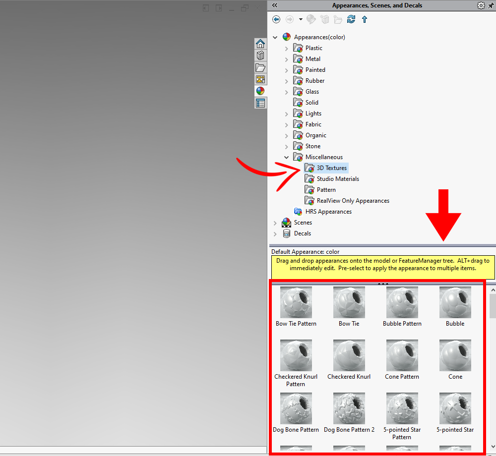
Many textural appearances are available by default in SOLIDWORKS. These textural appearances live in the “Appearances” tab of the Task Pane and can be found by navigating to Appearances > Miscellaneous > 3D Textures. The appearance files are stored in the SOLIDWORKS installation folder under “..SOLIDWORKSdatagraphicsmaterialsMiscellaneous3D Textures”. Other SOLIDWORKS appearances as well as custom images can also be used as textural appearances.
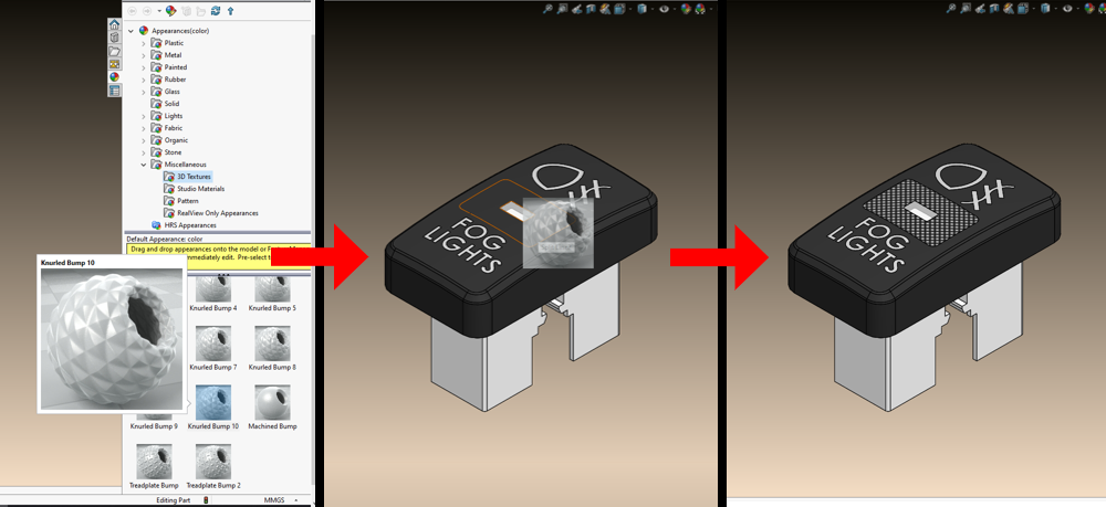
Applying an appearance or image as a textural appearance is just the same as applying any other appearance. We can simply drag and drop the appearance onto our part and then select the geometry we want to apply it to via the popup toolbar. And pro-tip—if you hold down the “ALT” key on your keyboard while dragging and dropping, the edit appearance PropertyManager automatically opens to adjust how it is mapped on the surface.
How to Edit a Textural Appearance
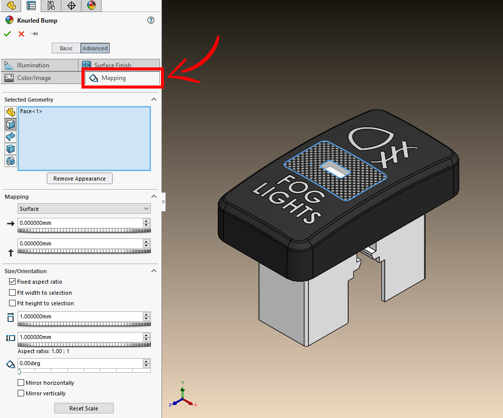
Textural appearances can be edited the same as any other appearance via the appearance PropertyManager, with specific focus on the “Mapping” tab. Here we control size, orientation, and position of the appearance on the geometry it’s applied to.
We can adjust the wrapping technique with these available options:
 Surface – Maps all points based on the UV texture coordinates of the model.
 Projection – Maps all points based on a projection direction.
 Spherical – Maps all points onto the surface of a sphere.
 Cylindrical – Maps all points onto a cylinder.
 Automatic – Maps to one of the X, Y, and Z axes; appropriate for most planar geometry.
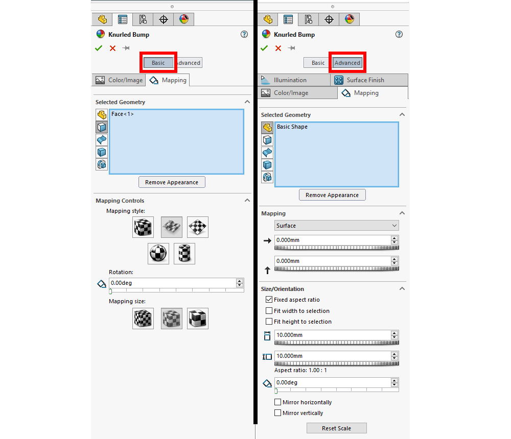
We have two sets of options for modifying the size and position of the textural appearance on our parts: “Basic” and “Advanced”.
The “Basic” option allows you to adjust the orientation of the textural appearance with a simple 0 to 360 degree rotation slider and gives you three options for size “Small”, “Medium”, and “Large”.
The “Advanced” set of options gives you finer control over these details. In the “Advanced” tab, you can finely tune the position, size / , orientation, and aspect ratio of the appearance on your geometry with numerical values. If the “Spherical” or “Cylindrical” wrapping techniques are selected, you have additional inputs to adjust the relevant axes and rotation of the mapped shape.
Using the 3D Texture Feature
In addition to the Insert > Features dropdown menu, the 3D Texture feature can also be found in:
- The “Mesh Modeling” tab of the CommandManager
- The context menu (found by right clicking a body in the “Solid Bodies” or “Surface Bodies” folder)
- The commands search bar by typing “3D Texture”
With the 3D Texture feature you must select which body you want to texturize and the specific texture you want to texturize it with. It’s worth noting that the 3D Texture tool transforms the entire body into a mesh graphics body, not just the geometry where the textural appearance is applied.
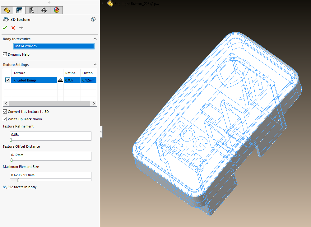
The PropertyManager shows a list of textural appearances that have been applied to your selected body. Here, you can toggle on and off the specific appearances that you want the 3D Texture feature to use. This list contains some basic information about each textural appearance.
3D Texture Feature Options
Displacement Method
You have two options for the displacement method, “White up, Black down” or “Black up, White down”. This determines which color represents the maximum displacement and minimum (zero) displacement. The “White up Black Down” checkbox in the PropertyManager controls this behavior.

Texture Refinement
Texture refinement increases or reduces the number of facets (triangles in the resulting graphics body). The higher the value, the greater number of facets. Generally, the greater the refinement, the closer the resulting geometry will match the textural appearance. The flip side of the coin is that with greater refinement comes increased complexity, file size, and rebuild times. Highly detailed grayscale images often require more refinement to capture the appropriate level of detail in the image.

Offset Distance
The offset distance controls the maximum displacement for the 3D texture. For example, a value of 1 mm displaces the part’s geometry 0 mm for black areas and 1 mm for white areas (with the “White up Black down” option checked). It essentially allows you to specify the maximum height of your texture.

Maximum Element Size
Finally, you can modify the maximum element size to control the facet size in the resulting graphics body. Typically, smaller values result in smoother, more refined shapes, but result in a larger number of facets.

Considerations When Using the 3D Texture Feature
Before you generate your 3D Texture, consider how the above inputs can affect your resulting graphics body. If the number of facets making up your graphics body is too large, it can significantly slow down system performance and could make the resulting graphics body unusable. Typically, around 3,000,000 to 4,000,000 facets denote an ideal upper limit when using the 3D Texture feature.
One way to reduce the number of facets in your graphics body is to break your part up into multiple bodies. This way you can use the 3D Texture feature only to the specific geometry you want the texture applied to instead of the entire model. This can significantly reduce the number of facets SOLIDWORKS needs to generate when texturizing our model.
Another consideration relates to the quality of the meshed graphics body. Sometimes the settings result in odd geometry or graphics bodies that are not “water-tight” (denoted as “Open”). With an “Open” graphics body, modifying geometry or attempting to 3D print the part can be difficult or impossible. In this case, changing the how the appearance is mapped or fine tuning the settings of the 3D Texture feature may be necessary.
Working with the Resulting Graphics Body
It’s important to note that the 3D Texture feature does not consume the original BREP geometry — you can still use it to adjust your 3D Texture, rebuild your texturized parts, or utilize it with hybrid modeling techniques.
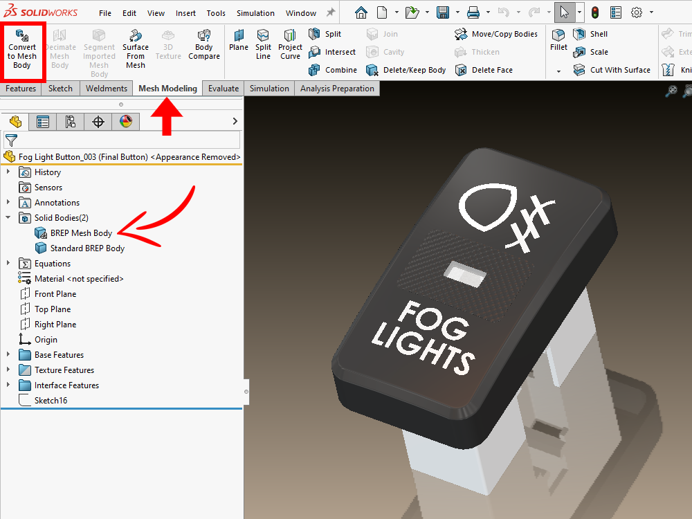
To perform any hybrid modeling techniques, you need to convert your graphics body into a standard mesh body. The “Convert to Mesh Body” command lives in the “Mesh Modeling” tab of the CommandManager. The resulting mesh can be manipulated with standard features or direct editing techniques to polish your designs even more.
Learn More about the 3D Texture Feature in SOLIDWORKS
Hopefully in this blog post you learned a little more about the 3D Texture feature and how to add textures to the surfaces of your parts. Check out our related blog posts and YouTube videos on this topic. We have some great ones well-geared towards using models with 3D Textures for 3D printing/additive manufacturing:
- SOLIDWORKS 3D Texture Tool – YouTube
- Creating 3D Printable Textures with SOLIDWORKS – YouTube
- 3D Printing Thursday – Best Practices to Texture Your Prints – YouTube
- Preparing a SOLIDWORKS Model for 3D Printing (hawkridgesys.com)
- The Top 10 New Features in SOLIDWORKS 2019 (hawkridgesys.com)
As always, if you have any questions, reach out to us! Contact us at Hawk Ridge Systems to discuss how the suite of SOLIDWORKS software can help improve your workflows and products.