Learn How to Optimize Your Design in SOLIDWORKS to Prepare It for 3D Printing
In today’s age of 3D printing, once-inconceivable manufacturing projects can now be brought to life right from your desktop. But whether you’re using a desktop-sized or an industrial 3D printer like Markforged, you’re likely starting in the same place – SOLIDWORKS. Therefore it’s imperative to optimize the design of your SOLIDWORKS model to prepare it for 3D Printing.
When preparing a model for 3D printing in SOLIDWORKS, there are a variety of adjustable settings that have a direct impact on the quality of the finished product. In this article, we’ll examine these parameters and show you how to get the best possible quality for your 3D printing projects.
To show the differences in quality, we’ll be using the SOLIDWORKS model seen below:

Figure 1: SOLIDWORKS Coffee Mug Model
I chose this model for one specific reason – there’s not a single straight line on it. The truth is, if your printing projects are generally prismatic, you’re unlikely to notice a major difference in printing quality as a result of adjusting settings in SOLIDWORKS. However, for projects making heavy use of arcs, circles, splines, or curves, the quality difference will be significant.
3D printers typically use mesh files for printing, which are tessellated approximations of CAD models made up of hundreds or even hundreds of thousands of triangles. Common mesh file formats include .stl, .3mf, and .amf, but regardless of which format you choose, the resolution (or a number of triangles in the mesh file) ultimately determines the quality of the final print. While the .stl format is more common, you may consider using .3mf if you have a multicolor printer, as appearances are supported.
To adjust the number of triangles in your model, access the SOLIDWORKS system options and choose the Export category. At the top of the dialog, you’ll find a File Format dropdown menu. Select the File Format dropdown and choose the appropriate file type. For this example, we’ll be using .stl, but the options for the other two formats are very similar.
Once you’ve selected the file type, you are presented with a variety of options:
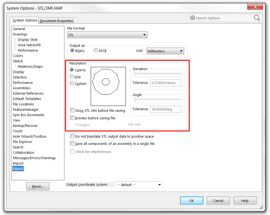
Figure 2: STL Export Settings
The first set of options allows you to select Binary or ASCII, and is unique to .stl files. Unless needed for legacy equipment or editing (the ASCII format can be opened in a text editor), Binary should be selected here, as it results in a significantly smaller file.
The resolution options highlighted in red is where the magic happens – here you’ll find two presets, Coarse and Fine, along with a custom option for manual adjustment. These preset controls the deviation and angular tolerances between the triangles of the resulting mesh file, with the Fine setting producing more, smaller triangles to meet the stricter tolerances. This results in a closer approximation to the intended design, and especially when dealing with curved geometry, a much cleaner surface (albeit at a larger file size). Generally speaking, deviation tolerance controls the tessellation of the entire model, while angle tolerance focuses on smaller detail tessellation (similar to global and local mesh control, respectively). The last two checkboxes in the highlighted area are useful for viewing .stl information and previewing the mesh prior to saving but have a tendency to tax system resources, and as such should only be enabled as needed.
For mostly prismatic designs, the Coarse setting will probably do the trick, and for many projects, the Fine setting will produce a decent surface quality. But for that very high-detail, curved designs simply click the Custom radio button. From here, use the sliders or input values to adjust the deviation and angle tolerances to your liking. A lower tolerance value (moving the slider to the right) will result in better surface quality. Beware, however, as very tight tolerances can have a major impact on processing time and the size of the resulting mesh file. In the figure below, the model using the Coarse setting (left) resulted in a file size of under one megabyte, whereas the custom high-resolution setting (right) produced a file nearly 30 megabytes. It should also be noted that diminishing returns should be expected when increasing resolution with respect to file size and finding the settings that are most appropriate for your project will likely take a bit of testing. We recommend beginning most projects at the Fine setting and making adjustments as needed. For more information on adjusting mesh export settings, consider taking a look at the SOLIDWORKS Help file on the subject.
Once the mesh files have been produced, opening them with SOLIDWORKS will allow you to see the tessellation. Below, the difference between the same model exported at the Coarse setting versus a high-resolution custom setting is readily apparent:
Coarse setting versus a high-resolution custom setting

Figure 3: Mesh Files Exported at Coarse Setting (Left) and High-Resolution Custom Setting (Right)
Finally, both mesh files were 3D-printed to show the end results in all their glory:
The final 3D printed design
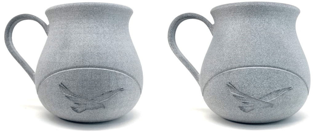
Figure 4: Mesh Files Printed at Coarse Setting (Left) and High-Resolution Custom Setting (Right)
Naturally, there are a variety of other factors that will influence the quality of 3D prints based on the specific equipment you’re using, but in this article, we investigated SOLIDWORKS system settings for optimizing quality on the software side. Do you have experience with 3D printers? Let us know how you’ve improved your projects in the comments! For more information, check out our YouTube channel or contact us at Hawk Ridge Systems today. Thanks for reading!


