Discretizing your CAD model into a simulation mesh is one of the most important concepts of finite element analysis (FEA) in SOLIDWORKS Simulation.
The mesh has a huge influence over the solve time and accuracy of the solution, and the two have an inverse relationship. Anyone with experience in FEA understands the balancing act of optimizing your mesh for accuracy and solve time.
If this is news to you, I recommend you explore how to achieve convergence of results and find accurate stress results with singularities.
In this blog, I am going to talk about some techniques to get your mesh exactly how you want it — refined in areas of interest and coarser in areas where the stress is not of interest.
With these techniques, you can get accurate results with the shortest possible solve time. They will focus on the boundaries of multibody parts or assemblies.
How to Align Common Nodes When Meshing
When you are meshing the interface between components, you have some options for nodes on the interface to be aligned.
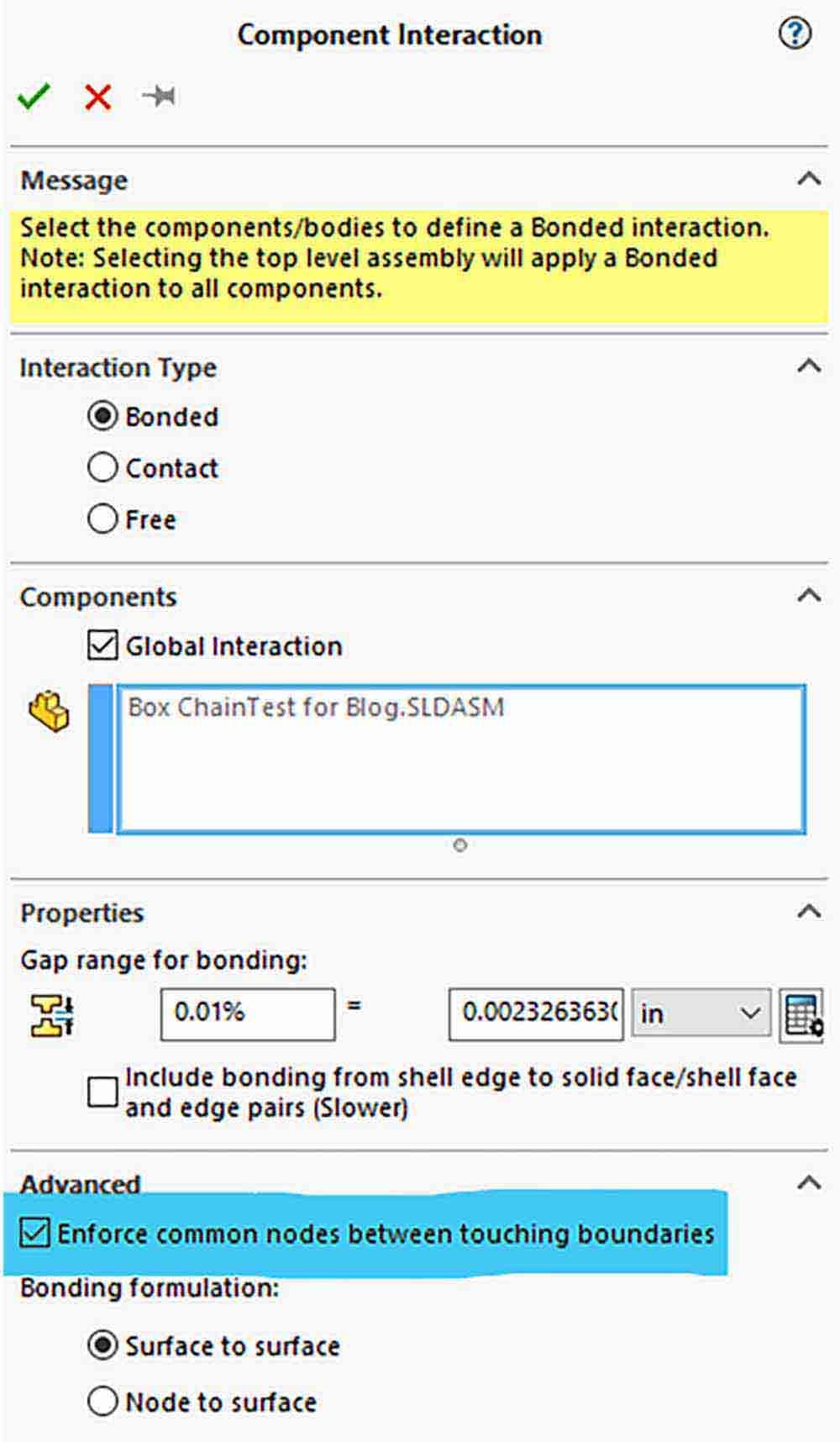
Within the global component interaction property manager, there is a check box to “Enforce common nodes between touching faces.”
Figure 1 below highlights the option to enforce common nodes when meshing. This option, along with mesh controls and settings within the global mesher, can drastically change your mesh, the time it takes to generate, and the accuracy of some results across the interface.
What Are Common Nodes?
Common nodes are meshing options where the nodes of adjacent parts are perfectly aligned. This meshing technique is ideal for a simulation where you are interested in the forces at the connection and will give you the most accurate bonding results.
Common nodes could be used for specifying glue, solid-state welding, or any process where you want the connecting areas to be perfectly bonded and understand the strength of that bond.
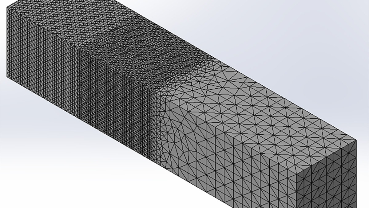
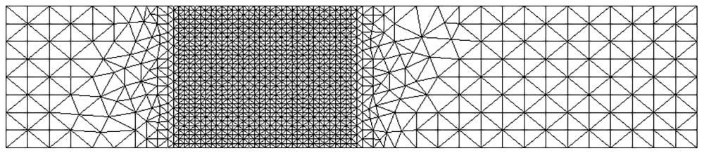
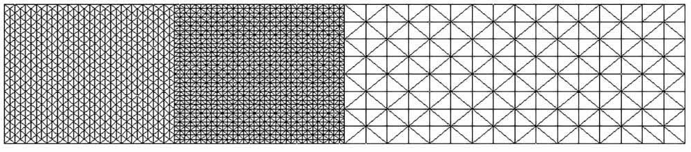
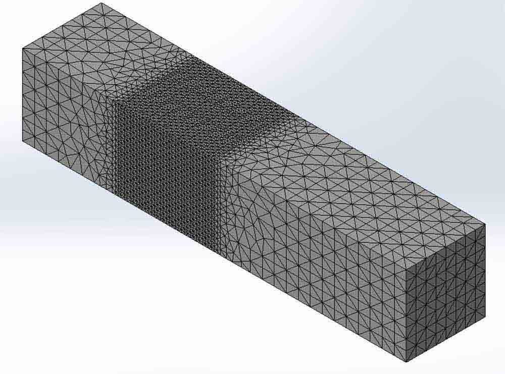
We can see an example of a model meshed with common nodes in Figure 2 and Figure 3 below. At the interface between components, the nodes of the mesh are perfectly aligned with their neighbor.
Looking at the interface between the first and second components from the left, we can see the fine mesh of Component 2 is influencing the mesh in the contact region of Component 1.

Drawbacks of Common Nodes Meshing
The common nodes meshing option does have some drawbacks, though. Enforcing common nodes is more computationally intensive when creating the mesh, but it is easier to compute the boundary equations because the displacement will directly transfer at the merged nodes.
The meshing time will be longer, but the overall solve time will usually be shorter as the boundary equations are simpler. The solve time could increase if the total number of degrees of freedom is unnecessarily inflated as the mesh of a smaller component is imprinted onto a larger one, as seen in Figure 6.
If you are interested in the stresses or free body forces at the interface of parts or bodies, use this method. You can get an accurate answer with a coarser mesh when using common nodes.
If you do not care about the shear stress at the interface or the forces the bonded faces are undergoing, then you can save on mesh time, total nodes, and degrees of freedom by taking a different approach.
Meshing with Independent Nodes
If you turn off the option to “Enforce Common Nodes between touching boundaries” and use a mesh control to change the mesh size of adjacent bodies, you will get results like the mesh in Figure 7 below.
The nodes of one body do not align with the nodes of the neighboring, meaning that the forces and displacements of one node will align with the face of an adjacent element. This alignment causes the solver to add calculations to distribute the nodal values to the closest nodes.
Depending on the mesh density elements on the contacting faces, they might be skipped due to no node touching them and causing them to not participate in the contact.
In general, a simulation that is meshed independently will create the mesh faster but will take longer to solve. Depending on the mesh density, you may get inaccurate forces, stresses, and boundaries.
What Is the Mesh Control and How Does it Work in Simulation?
Mesh Control is a tool used to change the mesh settings at a local region. You can select entities like faces, edges, or vertices, or you can select entire bodies or components.
With this tool, you can get your mesh looking exactly as you desire to optimize your solve time and accuracy.
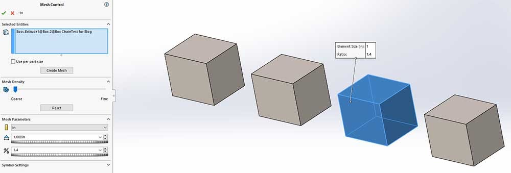
Figure 8 shows the mesh control property manager with the third body selected for a one-inch mesh control.
Incremental Meshing vs. Global Mesher: What’s the Difference?
Inside the Mesh Control property manager, there is a button to create a mesh. If you click on this, a mesh will be created for the components selected within the tool and will start a process called incremental meshing.
With incremental meshing, you can mesh all your components independently, and the components will not have common nodes.
The global mesher will mesh the entire model following a mesh definition hierarchy. The definitions in the mesh controls will take precedence over the settings defined in the global mesher.
The global mesher will also enforce common nodes based on the settings in component interaction. It will create a mesh quality plot displaying the mesh for you to evaluate.
If you are meshing incrementally using the mesh control tool, you will have to manually create a mesh quality plot to view the mesh.
To better understand how to use incremental and global meshing to get the mesh you want, we are going to look at five scenarios.
Scenario 1 – Mesh Control on Single Body with Common Nodes
In this Scenario 1, we will display how the mesh control behaves with the global mesher. The global component interaction is set to common nodes, so each body will share common nodes with its neighbor.
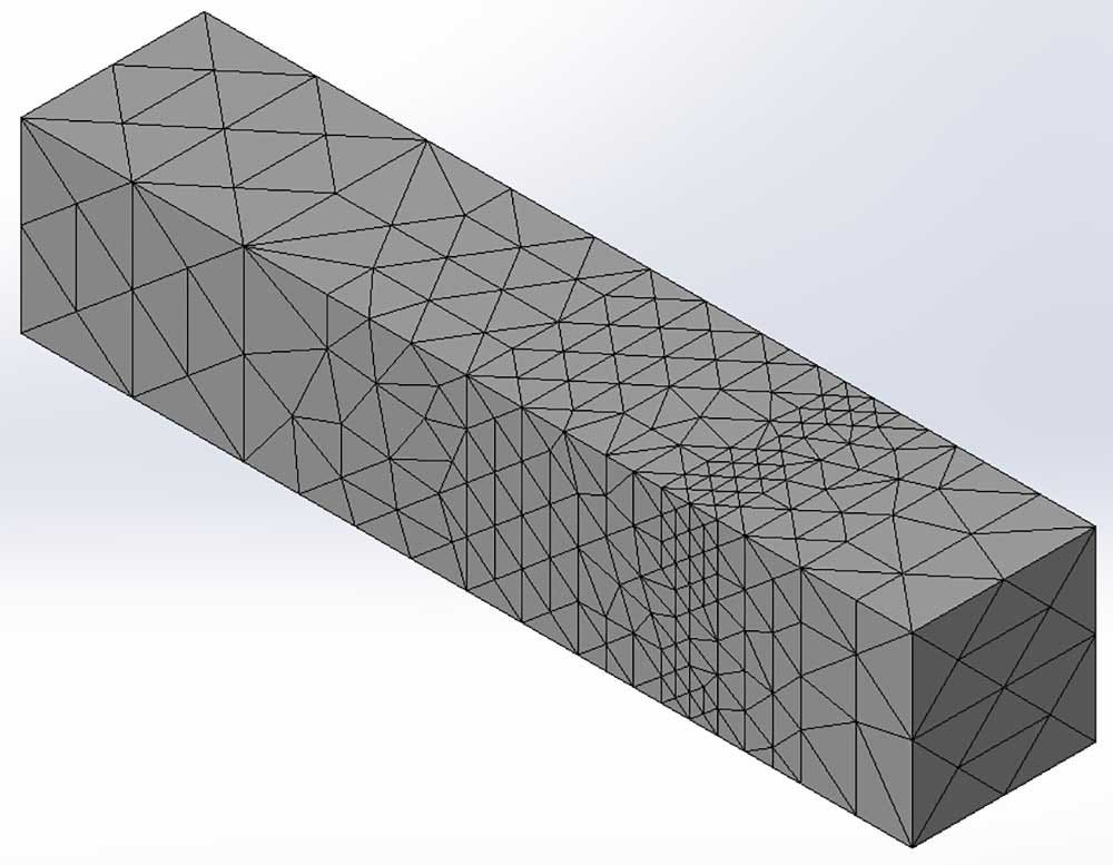
A Mesh Control was set on the second body to refine the mesh on that same body. We ran the global mesher, and as you can see in Figure 9, the second body has a more refined mesh but shares common nodes with the adjacent bodies.
In order for the common nodes to occur, the adjacent bodes have a fine mesh right on their boundary, but the elements get larger according to the growth ratio until reaching the value set in the global mesher.
Scenario 2 – Mesh Control on All Bodies Meshed Independently
For Scenario 2, we will refine the mesh on each body but have them meshed independently. We will compare the mesh time, solve time, and results to a similarly refined mesh with common nodes in Scenario 3.
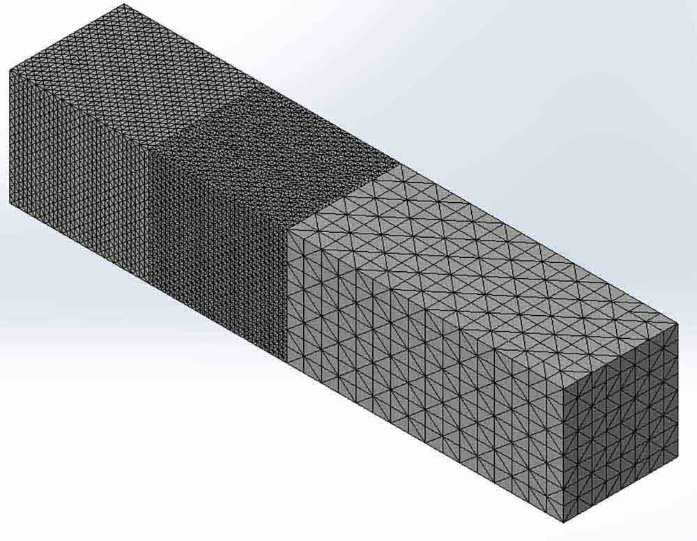
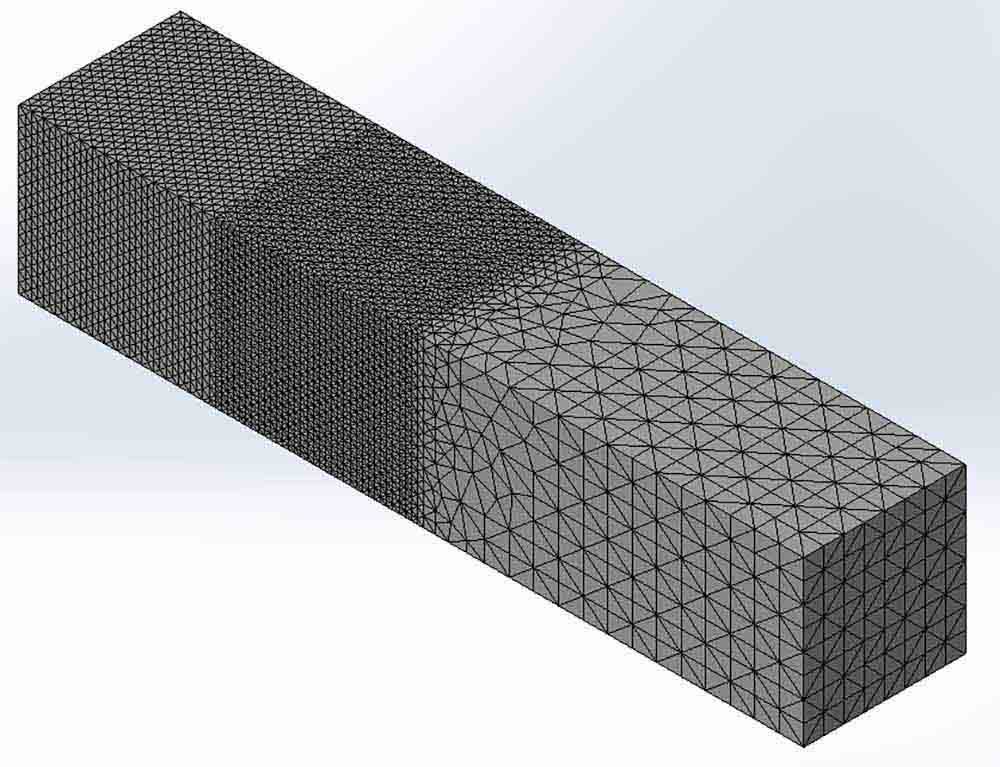
Figure 10 displays the mesh for Scenario 2. The global interaction is set to mesh independently, meaning that bodies will not share common nodes with their neighbors.
The first and second bodies have their own mesh controls, making them have a unique element size and not share common nodes.
The third and fourth bodies were selected inside the same mesh control feature. Since they have identical geometry, their nodes coincidently line up after we run the global mesher, even though the component interaction settings are set to mesh independently.
This phenomenon is just a coincidence because the bodies have identical geometry. This type of mesh took 6s to generate.
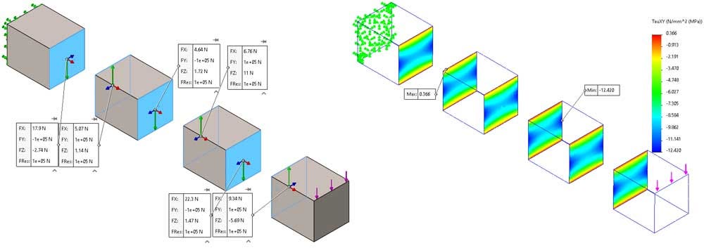
The results for Scenario 2 are accurate because the mesh is adequately refined. In Figure 11, we can see the resultant free body forces at the bonded boundary interfaces are equal and opposite, which is what you would expect in a static study.
Figure 12 is the shear stress in the direction of the applied force. Each adjacent face has the same distribution, and the mesh is refined enough to give accurate results.
Scenario 3 – Enforcing Common Nodes Compared to Scenario 2
We will compare Scenario 3 with Scenario 2. This mesh has the same mesh controls, but the global component interaction is set to enforce common nodes.
When we run the global mesher, all the bodies will share common nodes. Figure 13 is the mesh generated in Scenario 3, where bodies 1 and 2 have unique mesh controls and bodies 3 and 4 are in the same mesh control.
After running the global mesher, you get common nodes at the component interfaces. This mesh took 7s to generate, which is one second longer than its independent counterpart.
The free body forces and shear stresses are balanced at the interface between the components, as you can see in Figure 14 and Figure 15. The results are identical to the previous scenario because the mesh is very refined in both scenarios.
Time Comparison of Scenarios 2 and 3
Scenarios 2 and 3 use identical mesh controls, so they are a fair comparison for the time to generate the meshes and solve the simulations.
With this information, we can better understand how common nodes affect our mesh generation time and the time to solve the simulation.
Table 1: Time comparison of scenarios 2 and 3
| Scenario | Mesh Generation Time (s) | Solve Time (s) | Total time (s) |
| Meshed independently (2) | 6 | 23 | 29 |
| Common Nodes (3) | 7 | 19 | 26 |
As seen in Table 1, the independent mesh generates faster but takes longer to solve. The mesh with common nodes takes longer to generate but solves faster. Both studies yield acceptable results across the boundary of the components because of the density of the mesh.
Let’s see how a coarser mesh works with common nodes for the next two scenarios.
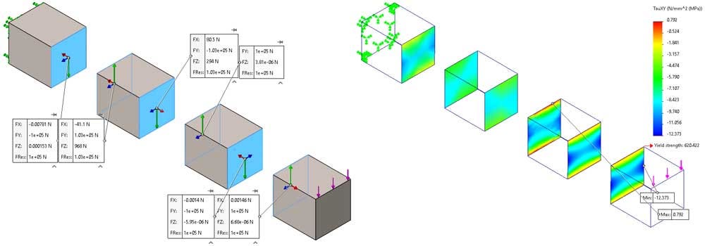
Scenario 4 – Coarse Mesh Control for Each Body Meshed Independently
Scenario 4 has the global component interaction set to meshed independently. Each body has its own unique mesh control.
An additional mesh control is added to the faces that connect the third and fourth bodies.The mesh control on the bonded faces is to refine the mesh in that region for more accurate results.
The resulting mesh from running the global mesher with the above settings is shown in Figure 16. Each body has its own unique element size, and the interface between bodies 3 and 4 is more refined due to the mesh control on the bonding faces. This mesh took 1s to generate.
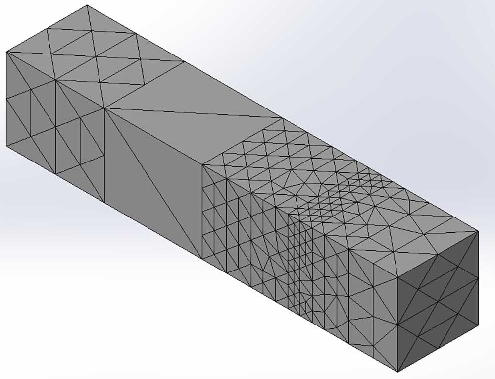
Since the nodes do not line up at the interface of the bodies, some assumptions are made in that region, which is amplified by the coarse mesh.
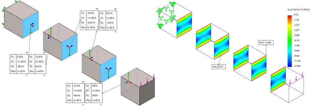
The free body forces of the first two boundaries are not balanced where the nodes were independently meshed, but the forces are balanced between the bodies that have the more refined interface. Figure 17 displays the unbalanced forces on the coarse independent mesh but balanced where the mesh is more refined.
Figure 18 shows the shear stress in the coarsely meshed bodies does not match their neighbors. With this coarse mesh, the independently meshed interfaces are not yielding accurate results.
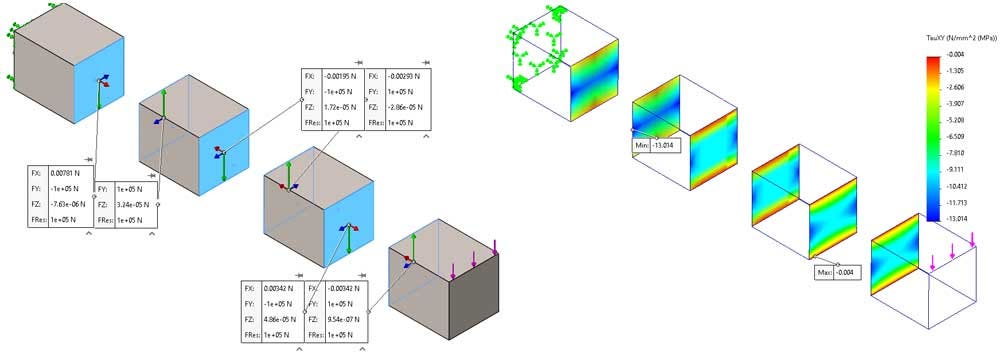
Scenario 5 – Enforcing Common Nodes Compared to Scenario 4
This final scenario uses the same mesh controls as Scenario 4, a fairly coarse mesh, but uses the component interaction option to enforce common nodes.
This option sets the mesh at the boundaries to a refinement level where the nodes at the interface line up.
In this example scenario, the boundary mesh is a happy medium where the mesh size at the interface is somewhere in between the two mesh controls, as seen in Figure 19. This mesh took 1s to generate.
The results from Scenario 5 are more accurate than Scenario 4 at the component interfaces because of the common nodes. The free body forces are balanced, as seen in Figure 20, and the shear stresses are identical across the interface displayed in Figure 21.
The identical interface results are what you would expect in a linear static study and give us confidence in the solution in that region, unlike the independently meshed results from Scenario 4.
Time Comparison for Scenarios 4 and 5
Since Scenarios 4 and 5 used identical mesh controls, it is fair to compare their solve times in Table 2.
The mesh was very coarse, so the two studies had identical mesh generation times. However, the solve time for the independent meshing was longer, just like we saw in the previous comparison for Scenarios 2 and 3.
Table 2: Time Comparison for scenarios 4 and 5
| Scenario | Mesh Generation Time (s) | Solve Time (s) | Total time (s) |
| Meshed independently (2) | 1 | 1 | 2 |
| Common Nodes (3) | 1 | 0 | 1 |
The Final Point
All the scenarios had the same displacement, so regardless of the meshing strategy at the connecting interfaces, the displacement profile was the same.
Using the common nodes options, they take longer to generate the mesh but will solve faster than an equivalently sized mesh that is independent.
A mesh with common nodes will reach an accurate solution at the boundaries with a coarser mesh than its independent counterpart.
From these results, it looks like meshing independently has no positive benefits. However, depending on the complexity of the model and mesh size differences of the components, it can drastically reduce your element count and solve time.
For more information, contact us at Hawk Ridge Systems today. Thanks for reading!


