In today’s complex high-tech landscape, devices are becoming more compact, dense with components, and power-hungry. Any of those aspects can lead to excess heat and potentially cause serious issues.
We know this from personal experience of devices overheating, causing slowdowns or performance drops. Identifying potential thermal issues through simulation early in the design process can help ensure products work as expected and limit risk factors to the system and end user.
In this blog, we’ll discuss a few core aspects of thermal performance in electromagnetic systems and explore examples of how simulation can identify issues. Then, we’ll dive into how SIMULIA CST Studio Suite can simulate electrical and thermal conditions in one interface, making our lives as electrical engineers easier.
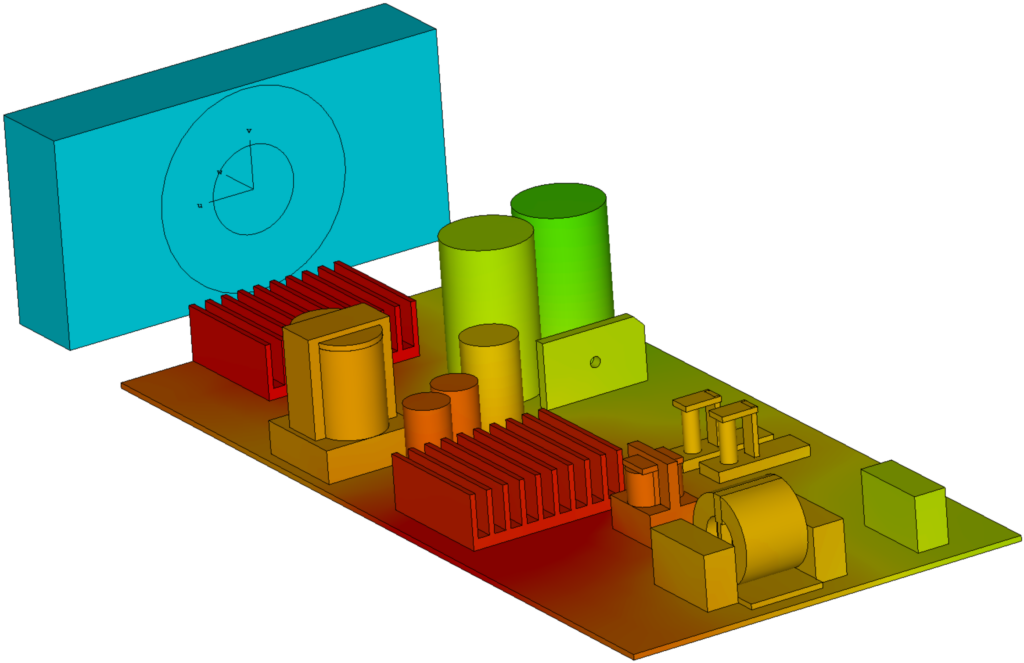
How We Understand Thermal Concepts Related to the Electronics We Simulate
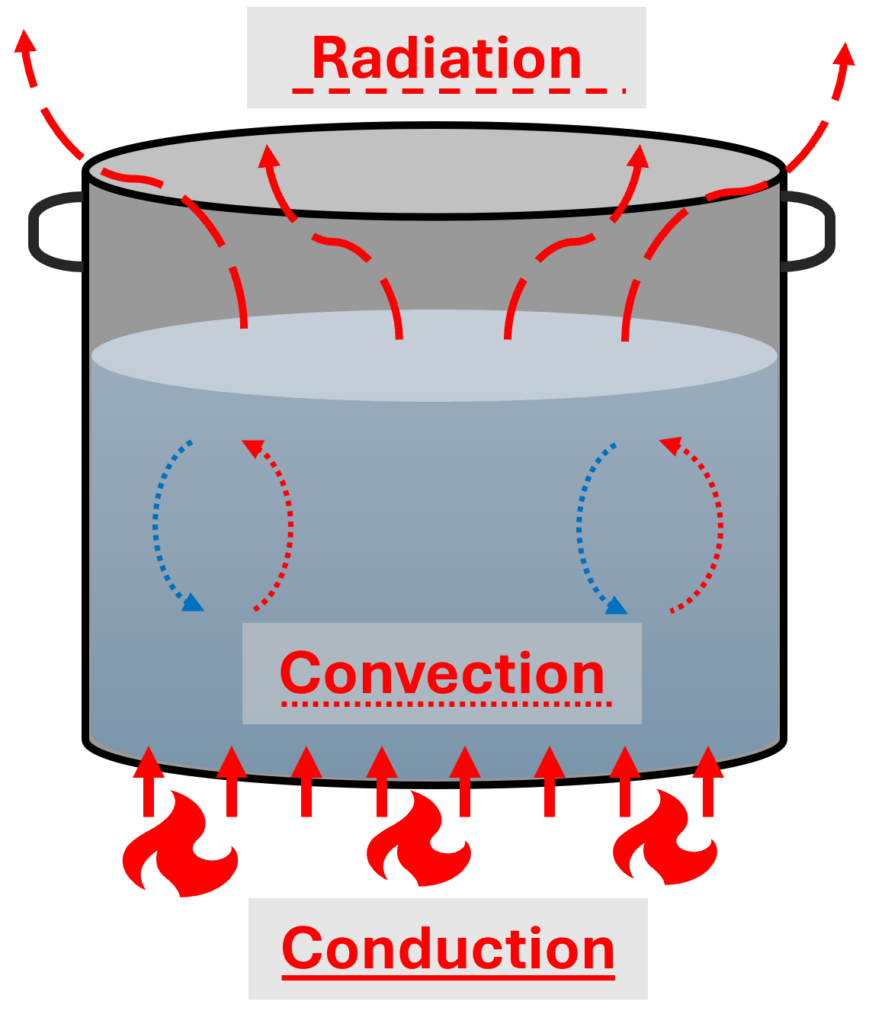
Heat transfer is something we can naturally understand but may lack the terminology to explain. Classic examples of the different forms of heat transfer are often shown with a diagram of a pot on a stove.
A heat source, such as a flame, transfers thermal energy to the system via conduction or contact. Fluids will transfer that heat energy through convection or internalized movement like currents. The final piece would be radiation, where the heat energy flows outward through the air or medium.
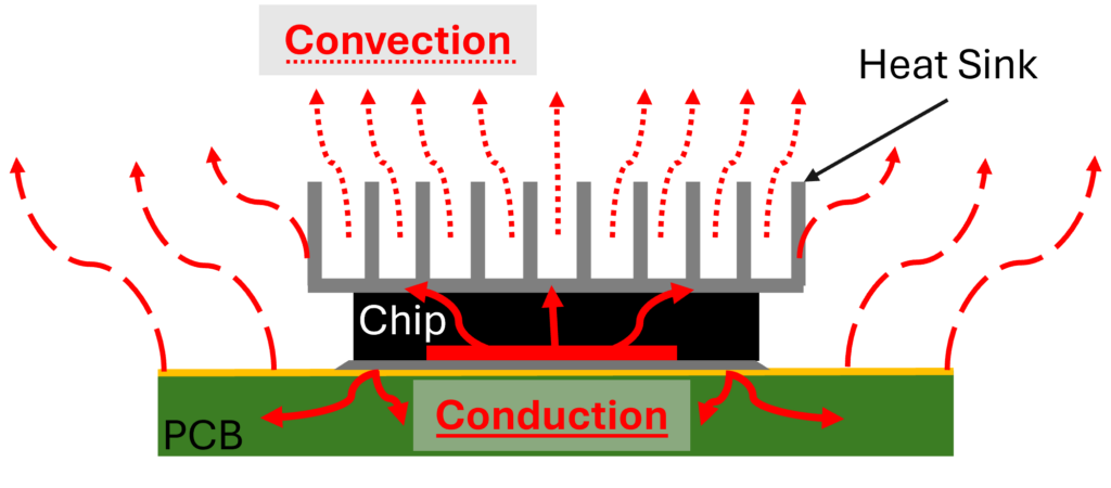
Luckily, we can show the same concepts for how it would work in electronics with a printed circuit board (PCB), chip, and heat sink. The core difference between the two is what is generating the heat in the system.
For electronics, the components’ input signal power and material properties will dictate how much heat is generated. With this in mind, we can see that conduction is the primary mover of thermal energy in the system.
2 Major Scenarios Where Thermal Simulations Matter in Emag Applications
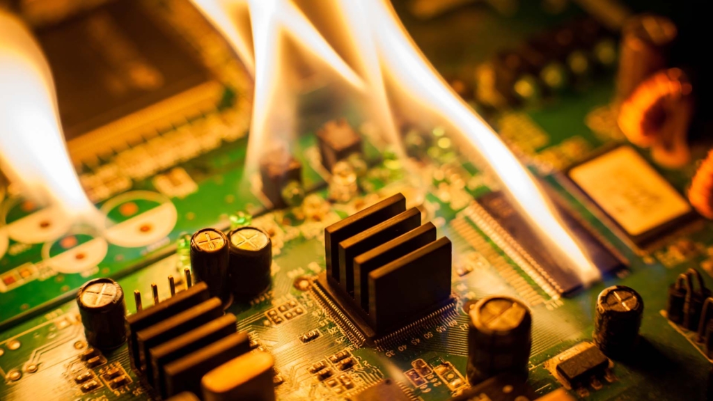
Plenty of situations exist where electronics and electromagnetic devices can produce excess heat.
1. Reducing Heat from PCBs
Starting at a smaller scale, PCBs can generate heat from components, high power inputs, and sub-optimal traces and transitions, which can lead to signal integrity issues, delayed switching speeds, and decreased lifespan if not addressed.
These issues can be found in low frequency designs that may have transformers and power planes that generate a lot of heat, as well as high frequency systems like 5G antenna arrays due to the density and frequencies of operation.
These PCBs are generally found in some sort of enclosure, which can present its own set of thermal problems. The enclosure provides protection — both physically and for EMC/EMI requirements — that can trap heat.
Adding vents and fans can reduce the thermal load internally, but there could be tradeoffs on EMC/EMI performance that simulation can identify and optimize to ensure the best tradeoffs.
2. Adding Safety Measures
Any device close to a person needs to be safe from overheating. Devices like wearables, high-power antennas, and even MRIs can benefit from simulating thermal effects to ensure compliance and safety while meeting performance specifications.
Testing Thermal Conditions with SIMULIA CST Studio Suite
SIMULIA CST Studio Suite is already known as a leading electromagnetic simulation tool. It has fully formed, powerful thermal solvers that take system-level emag simulation to a whole new level.
CST can provide valuable insights at the design stage and save time in testing or potential failures down the line.
2 Main Solvers
Users can choose from two main solvers:
- “Classical” finite element solver is used for situations where the internal thermal conduction is the focus. This does not factor airflow and will need some coefficients manually input. It is generally a faster simulation with less overall complexity but a narrow range of results.
- Conjugate heat transfer (CHT) computational fluid dynamics (CFD) solver is incredibly powerful. It can simulate conduction, convection, radiation, and airflow and automatically calculate the thermal properties needed. Simulation run times can be longer since it solves the entire 3D domain and processes more information, yielding more results.
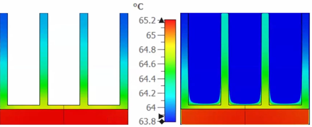
Within those solvers, you can also specify whether it is:
- Steady State: This is not time dependent. A simulation of this type would focus on an element that is at temperature and does not vary.
- Transient Simulation: This is time dependent. A simulation of this type would factor in the time it takes for an element to increase or decrease temperature over a timespan.
Other Full-Fledged Thermal Solvers
In addition to full-featured solvers, SIMULIA CST can simulate fans, multi-fluid systems, altitude adjustment, and more. All of which leaves CST as a viable path for direct thermal simulations if desired.
Emag-Thermal Workflow
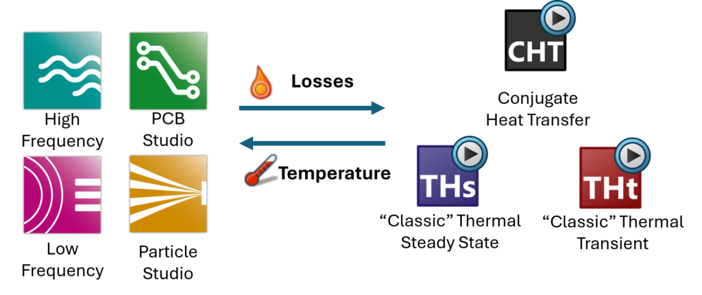
The true power is in the coupled emag-thermal simulation workflow. A coupled workflow will take the electrical losses performed in an electrical simulation and import them as thermal sources to the thermal simulation.
Enabling a bi-directional workflow would then feed those thermal losses back into the electrical simulation and continue the process until a steady state is reached. This is how you can see exactly how your system will perform electrically under a thermal load.
Key Ways to Work with PCB Simulations
Performing a simulation on a PCB with high-speed components, high-power inputs, or complex multilayer configurations could be a computational headache.
Fortunately, SIMULIA CST Studio has many tools to ease this workflow and enable accurate results without sacrificing excessive time simplifying the model or wasting time in long simulation runs.
Easily Import Models
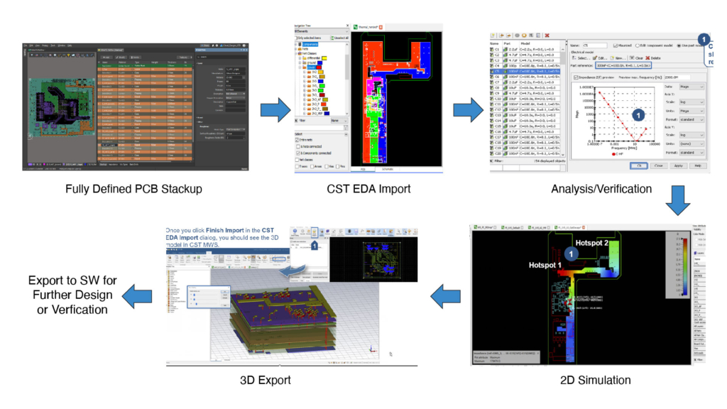
The electronic design automation (EDA) import wizard makes it easy to:
- Import a fully defined PCB stack-up
- Select which components, areas, or nets to focus on
- Whether a 2D or 3D simulation will be performed
There are thermal options, such as defining the heat source, power in watts, and component heights that can be defined as needed.
Simplifying Complexities in Multilayer Boards
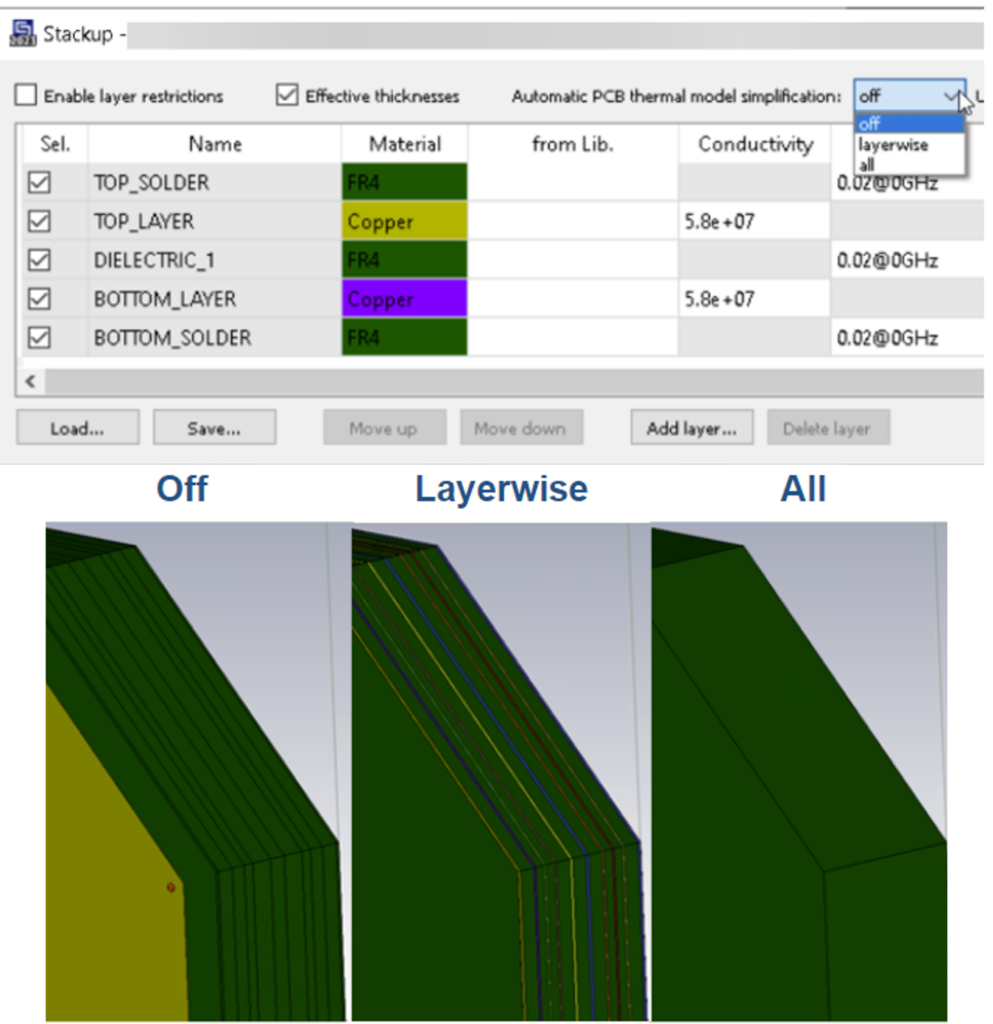
Multilayer boards can have over 20 layers, but not all details are needed for a thermal simulation.
In CST Studio, these complexities can be simulated directly, meshing each layer and material, or through a simplification of common areas. The simplification step could be done manually, with the user entering estimated values and manually defining sections.
Alternatively, CST has a much easier workflow that semi-automates this process, allowing users to easily determine how much detail is needed for their simulation.
Plating Thickness and Constructing Detailed Material Properties
Vias are a critical component of any complex PCB. They are used for impedance matching, isolation, and even for thermal management.
Since there can be hundreds to thousands of vias in any board, considerations need to be taken to ensure efficient simulations and total mesh count.
During the EDA import, vias are imported as solid cylinders since that is what is electrically relevant.
When thermal effects are taken into consideration, CST has options to enable plating thickness to be factored and wizards to construct more detailed material properties that matter for thermal simulation.
Consider the IR Drop
One of the most direct ways to analyze the thermal effects of a PCB is to look at the IR drop while performing standard signal integrity checks.
IR drop, otherwise known as voltage drop (Ohms law V=IR), shows the relationship between the flow of current and the drop in voltage across the PCB traces.
This analysis generally looks for areas with high resistance. Excessive IR drop can range from impacting the switching speed of a chip to reducing the component’s lifespan.
Simulation can help identify problem areas, and changes can be made before the boards are sent to fabrication.
IR Drop Example with Measured Results
In practice, performing an IR drop thermal analysis in SIMULIA CST is an easy process to grasp by utilizing some of its powerful tools.
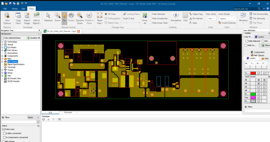
1. Import Your Board
The EDA import brings in a fully defined board and most components with just a few clicks.
Selecting the nets, traces, and components to analyze is done through easy wizard menus. At this point, the simulation is being performed in 2D, and the results can be viewed in 2D as well.
The goal of this simulation is to identify the potential sources of the voltage drop. Once known, in this case, the components have the most loss, a thermal co-simulation can be configured.
This is all done in the same main CST program without switching between software packages.
2. Identify Your Heat Source
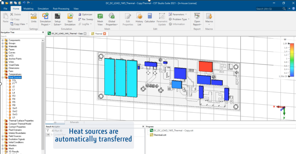
The thermal simulation will be performed in 3D, which is accomplished by using the same EDA import and simply defining the import as 3D.
For situations where there are a lot of components or features, simplification can help speed up the simulation. This can be done on components and even layer simplification.
A thermal simulation needs a heat source, and in this case, it is directly imported from the losses measured in the IR drop simulation.
3. Choose Your Solver
The CHT solver is the best fit for this application and will provide the most accurate results. After the simulation is completed, different thermal results can be reviewed and analyzed to determine the full thermal effects and can be used as focal points for improvement.
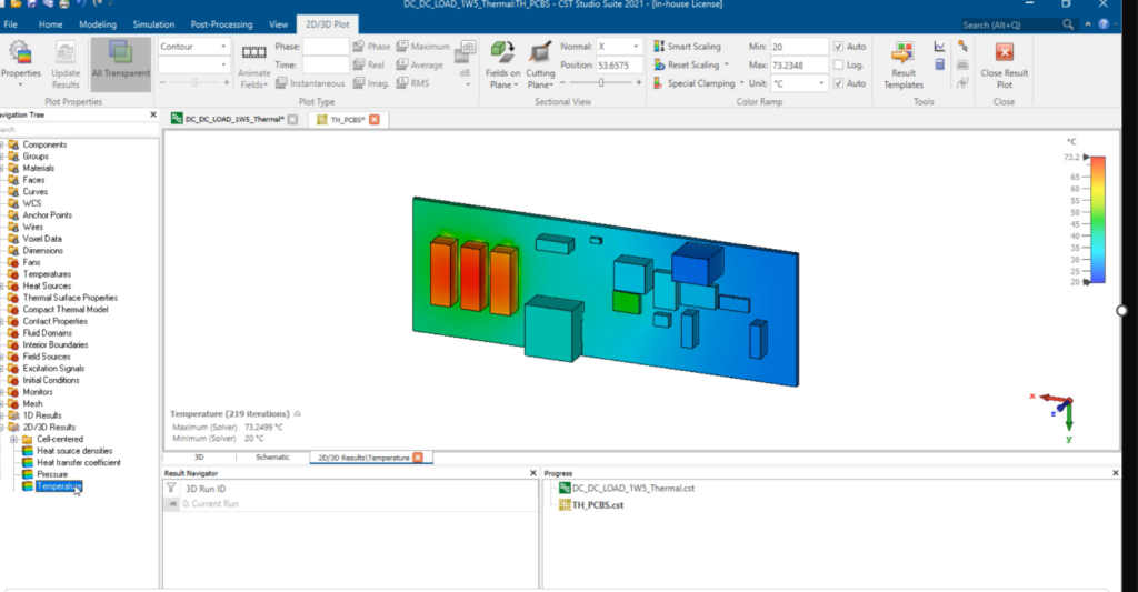
Since the CHT solver was used, aspects like flow can show broader scale effects of heat dissipation. Comparing the results to thermal imaging, the simulation shows very close accuracy to real-life measurements.
How Should You Deal with Excess Heat?
For an individual component, the placement of a heat sink can dissipate thermal load locally. SIMULIA CST’s advanced meshing techniques and workflows can simplify the optimization of sink geometries with just a few clicks and detailed results.
Another option to reduce the direct heat of traces would be to optimize trace geometries via modification and overall signal path changes. These steps will have a direct impact on signal integrity, so an electrical simulation should be performed to ensure proper performance.
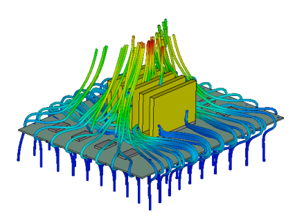
PCBs are often found in a next higher assembly (NHA), such as a box or other type of enclosure. This presents a challenge in dealing with the heat that has dissipated from the board. Even if it is within the operating range of the board, it may be problematic inside the enclosure.
Heat is still generated, but at some point, it needs to go somewhere. This is where fans and vents come into play, and the CHT solver makes this analysis a breeze.
Flow can be modeled using fans, either imported or generated with the fan wizard, natural convection, or with a boundary condition. Sometimes, a fan may not be a viable option, so vents or slots are used to try and allow for enough airflow for the heat to escape.
SIMULIA CST has easy options to configure different types of slots to see how they impact the flow in the system.
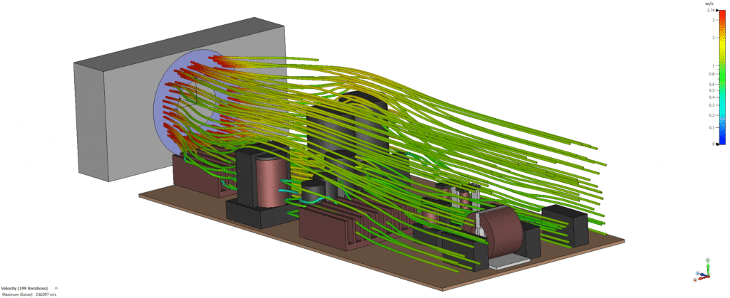
The ability to simulate all these options in one interface means fewer software packages to learn, more streamlined workflows, and more confidence in your design.
The Final Note
Modern electronics are more complex than ever, leading to more complex problems. Ignoring these complexities by not simulating them early in the design process could be a recipe for headaches down the line.
SIMULIA CST Studio Suite can give engineers the tools to fully analyze, optimize, and troubleshoot any electromagnetic problem — both electrically and behaviorally (how thermal behavior impacts the system).
And we’ve only scratched the surface of the thermal simulation capabilities of SIMULIA CST Studio Suite.
Connect with our team at Hawk Ridge Systems if you would like to learn more or see the software in action.
