In this blog, I will show you an easy and straightforward process to convert scan data into usable surfaces inside of SOLIDWORKS. As an example, I will be using an STL file which is a scan of a leg with the objective of making a custom connection interface along the back of the leg in the calf region. This interface region will be used to model a custom leg brace that will later be 3D printed.
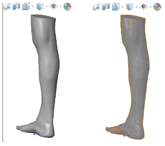
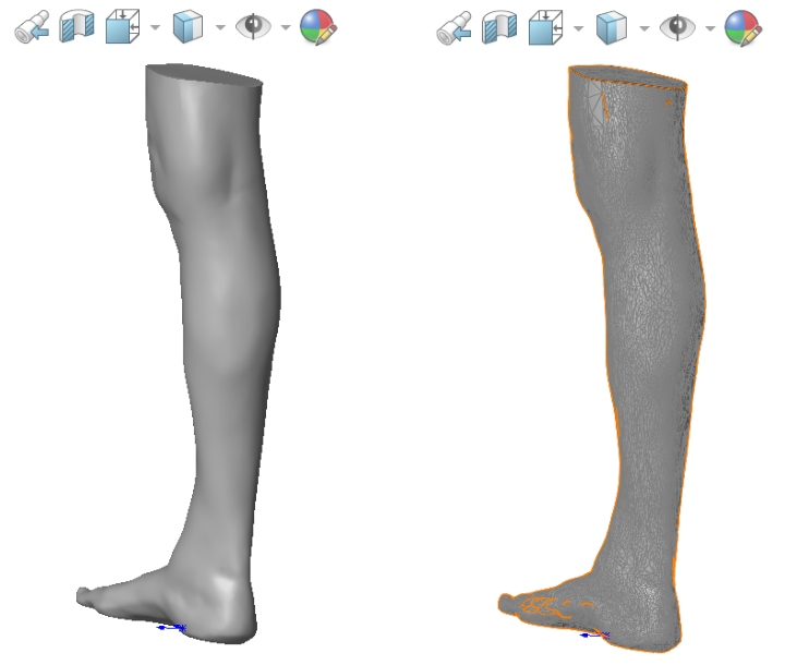
When I import the scan into SOLIDWORKS, it is a very clean mesh body, but it is made up of a bunch of small faces. Figure 1 shows the imported scan with the display style set to shaded. It is a high-quality scan and looks smooth. Figure 2 shows the same model with the display style set to shaded with edges. In this image, we can see that the scan is made up of many small faces. This faceted surface is hard to work with inside of SOLIDWORKS when trying to build the exterior surface or use it as a reference for a new part. The process in this blog will show you how to create a single smooth surface from that mesh file to use for a custom interface for the calf portion of this leg. SOLIDWORKS has some newer features (2019) for working with mesh bodies that make this a simple four-step process.
1. Import scan as Mesh Body
2. Slicing tool to create loft profile sketches
3. Fit Spline the curve to get smooth un-tessellated sketches
4. Lofted Surface
There are four steps required to create a smooth, singular-faced surface or solid body from a mesh body. But the general idea is to trace the body where it intersects different planes and then loft those traces. The first step is to import the scanned STL file as a Mesh Body, then use the Slicing command to create Reference Planes and Sketches for the loft profiles. The next step is to use the Fit Spline or Smooth Spline sketch tools to get smooth, untessellated sketches, which are ideal for lofts. The last step is to add a Lofted Surface between the profiles. Easy as that!
Import Scan as Mesh Body
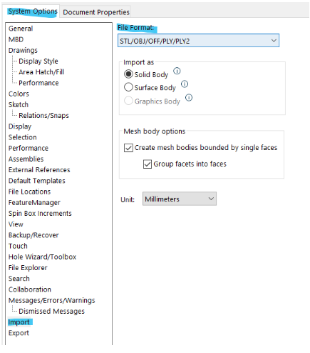
The first step is to import the scan data as a solid body. As seen in Figure 3, you can select the import options within the system options of SOLIDWORKS or the open dialogue box. Ensure that the STL is imported as a solid body with the option to group facets into faces. That checkbox is the first step to smoothing out mesh data as it will reduce the total number of faces in the import.
Slicing
The next step in the design process is to create planes and sketch profiles where the scan intersects those planes. These sketches serve as the loft profiles of the final surface. The slicing tool is a one-stop-shop for performing all of these functions while organizing the features neatly into a folder in the feature manager design tree.
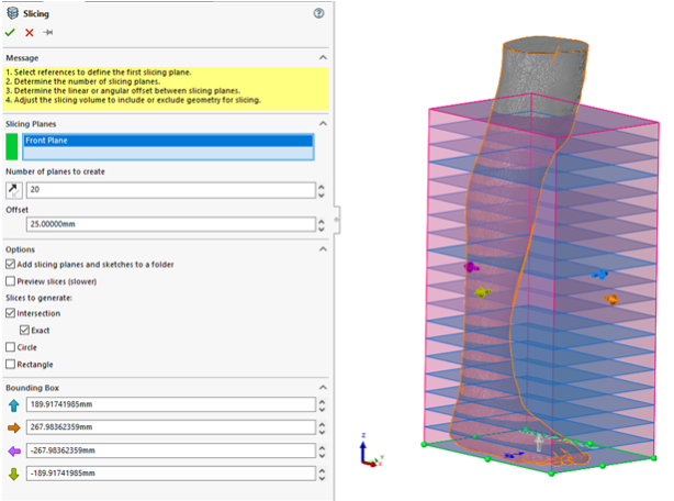
This slicing tool creates adjustable planes that are parallel to a reference plane, along with a sketch where each plane intersects the scan. This results in a series of sketches that are perfect for the lofted surface tool. Figure 4 demonstrates how the slicing tool allows you to adjust the number of planes to create and the spacing between them. By default, the tool evenly spaces every plane, but after slicing, you can adjust the spacing of each plane relative to the reference plane to ensure that you capture every contour of the scan. Additionally, you can run this tool in series to obtain more densely placed planes and sketches in a particular region of the model and coarser spacing in others.
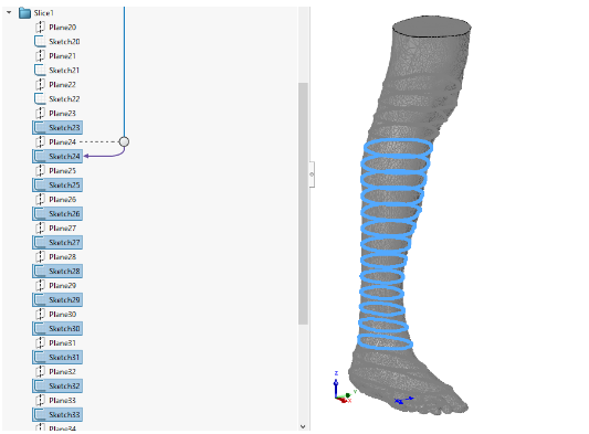
The sketches and planes created by the Slicing tool can be automatically sorted into a folder in the feature tree, as seen in Figure 5. Each plane has a reference dimension to the original reference plane and can be adjusted at any time.
Fit a Spline to the curve to create a smooth, untessellated sketch
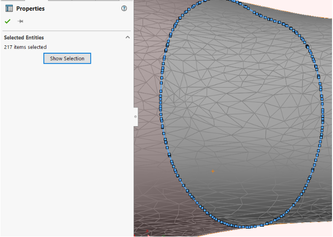
Since the mesh body is made up of many small faces, the spline created from the intersection of the body and plane is also made up of many small splines. Every face the plane intersects creates a spline entity in the sketch, so the tessellation of the scan is carried into the sketch. We can see in Figure 6, 217 entities make up the curve.
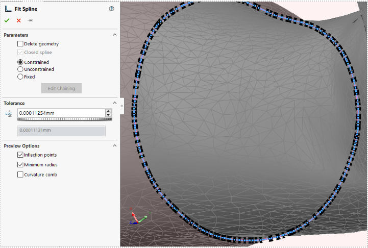
To smooth it out, the Fit Spline sketch tool can be used. It will convert the 217-entity spline into one single smooth spline, as displayed in Figure 7. This step is necessary because every entity in a sketch will generate a face, and each one of the endpoints will generate a loft connector. 217 faces would not give us a smooth surface to finish. This is a crucial step in getting a smooth loft.
Lofting the Surface
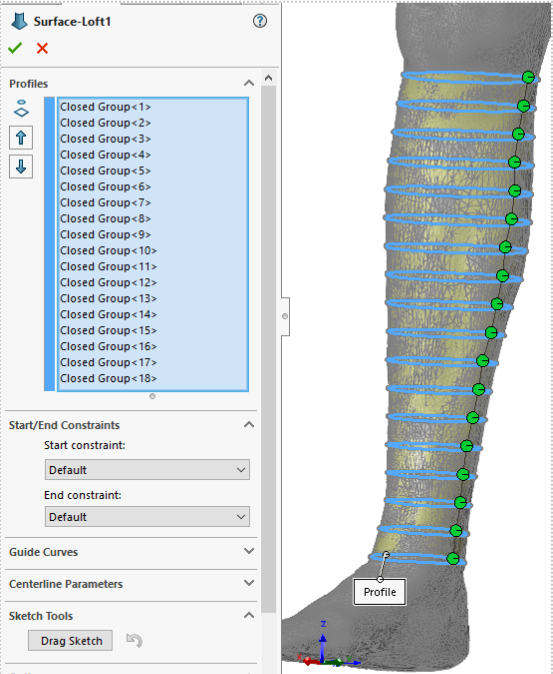
The last step of the process is to loft all the profile sketches together to create a surface or solid body. Figure 8 displays the Surface Loft property manager where all the sliced sketches are selected as profiles. The preview in the graphics area gives us a nice smooth surface. You may need to adjust the loft connectors to ensure that the resultant loft is not twisted or folded.
Results
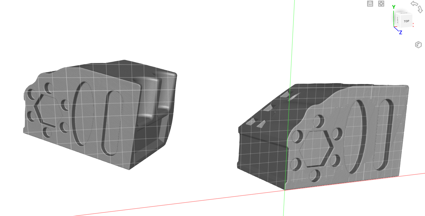
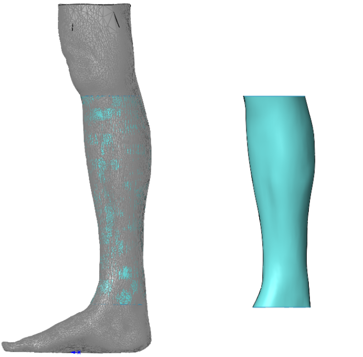
As we can see in Figure 9 and Figure 10, the result of this procedure is a single-faced smooth surface that I can use to contour the calf connection point of my design. All the details of the scan are still preserved, such as the definition of the calf muscle and the shape of the shin bone. The resulting single-faced smooth surface is exactly what I need to create a custom connection interface for this leg scan.
Summary
This blog shows you four easy steps to take in order to go from tessellated scan data to a smooth, usable surface inside of SOLIDWORKS. The longest part of this process was the fit spline of each sketch. When I used Ctrl-A to select all the entities, there was a bit of a delay as SOLIDWORKS collected the 200+ splines in the sketch. This process also compounds as the more profiles you have, the more times you must repeat the process. It was a little tedious but was well worth the few minutes it took because the resulting surface is identical to the scan and extremely easy to work with.
For more information, check out our YouTube channel or contact us at Hawk Ridge Systems today. Thanks for reading!