Have you ever been curious about how to efficiently route fiber into Markforged 3D printed composite parts? In a previous blog called “How to Select the Correct Fiber for Your Markforged Application,” we reviewed some real-world applications which make use of continuous fibers that Markforged printers can inlay into plastic parts. Today, we’ll be taking a look at some techniques that can be used to create more efficient and stronger fiber layouts.

Fiber Fill Types
Before transitioning to the patterning techniques used to place fiber into parts, we’ll first cover the differences between how Markforged uses their Eiger software to inlay fiber. Within Eiger, the two main methods for placing fiber are known as Concentric and Isotropic.
As the name implies, Concentric fiber is placed alongside the walls of a part. By default, the software will create a pattern of concentric fiber rings to run alongside all walls within a layer. Users can more finely tune this setting to reinforce only exterior walls or interior holes. Users are also able to modify the number of fiber rings when using Concentric fiber. This particular layout is great for reinforcing against compression or bending forces that are parallel to the X/Y plane of print layers.
An animated example of the concentric reinforcement settings.
On the other hand, the Isotropic pattern creates a weave of fiber that alternates by 45 degrees each layer, though the angle of these rotations can be manually adjusted to fit different parts. The weave provides additional strength against torsional forces, or against compression that comes from the Z direction of part print layers. This pattern also allows users to set and modify concentric fiber rings, so this is a great option for universal strength.
An animated example of the default weave created by the Isotropic fiber configuration.
A little fiber goes a long way, and as we’ll go over in the following sections, it is not always best to choose a fill type that contains the most fiber.
The Sandwich Panel
The first technique we’ll cover is known as the Sandwich Panel. This is the default behavior of Eiger when fiber is enabled, as it splits the set number of fiber layers and places one half near the top and bottom of a part. This behavior follows Beam Bending Theory, which demonstrates how bending forces place one side of a beam in tension while compressing the other side. Like an I-beam, the compression and tension of fiber sandwich panels helps to act against deformation along the neutral axis.
When subjected to bending forces (F), the top of the beam shown above would be compressed, while the bottom is under tension. This helps prevent deformation along the neutral axis (X).
Fiber performs best while under tension, so this default behavior will provide a large amount of strength to many parts. In the case of uneven geometry in the Z direction, Eiger can be utilized to manually place panels of fiber.
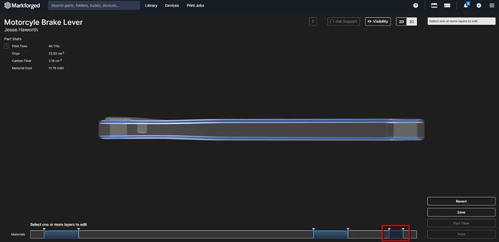
An example of a partially manual sandwich panel. The original setup contained eight layers of fiber, so four layers were placed in the small feature that comprised our top layers (marked in red).
Shelling
The second technique we’ll look at is referred to as Shelling. This is a good method for providing an entire part with strength against forces that originate from multiple directions. As indicated by the name, this is done by creating a shell of fiber within a part.
To show this example, we’ll use HSHT Fiberglass inside of a thermoset-mold piece. To give the part resistance against torsional and compression forces, we’ll keep the two isotropic panels that were set by Eiger near the top and bottom of our part. To further reinforce this part, we’ll place another isotropic panel under the main cavity of our mold. When shelling a part, it is a good practice to place a panel of fiber close to major geometric changes.
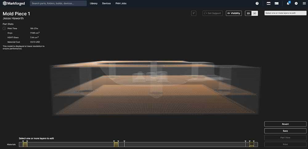
The two sandwich panels in addition to the custom placed middle panel form the base of our shell.
Because we are using the default isotropic panel rotation of 45 degrees, we’ll keep our panels in intervals of four to keep the benefits even in all directions.
With these three simple panels, our mold piece is already much more resistant against the clamping forces it would have to withstand while in use.
However, the top half of our part still contains the main cavity and many holes that will likely need reinforcement. To help provide strength in these areas, we’ll create a custom fiber group between our top two panels and set a Concentric pattern.
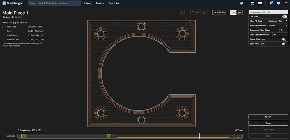
The concentric rings in our large group help provide strength to the main cavity and holes.
To complete the shell, we’ll also set a concentric fiber group in the bottom half of our part. These two groups provide strength to individual features, but they also help to support the load placed on our isotropic panels.
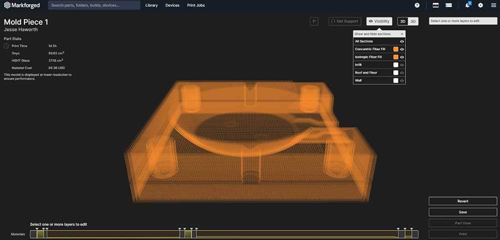
The entire inner shell with Onyx layers hidden for visibility.
Striping
The next technique, which is referred to as Striping, has been made extremely easy by a recent addition to Eiger. Like Shelling, this method is meant to provide good, universal strength to an entire part or feature. The main idea behind striping is to keep even spacing between multiple fiber panels so that one area is not stronger than the other.
To demonstrate this, we’ll use the coupling jaw part pictured below. As with the previous technique, we’ll keep the default isotropic panels.
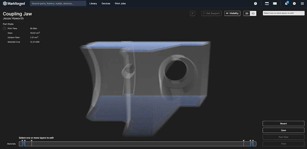
Our coupling jaw is set up with the two default sandwich panels.
Since this geometry is symmetrical in the Z, we’ll set up fiber stripes for the entire part by first selecting the group where we would like to place fiber. With a group selected, we can toggle fiber and set the Fiber Pattern Type to Stripes. Once this is done, setting our evenly spaced stripes is as simple as using the Stripe Count and Layers Per Stripe sliders to adjust the group.
An animated example of how Eiger will automatically adjust a striped group based on settings.
Optimizing
The final fiber technique we’ll cover today is simply known as Optimizing. This one is a bit on-the-nose, but it is all about using what we know about fiber and routing techniques to optimize cost and performance.
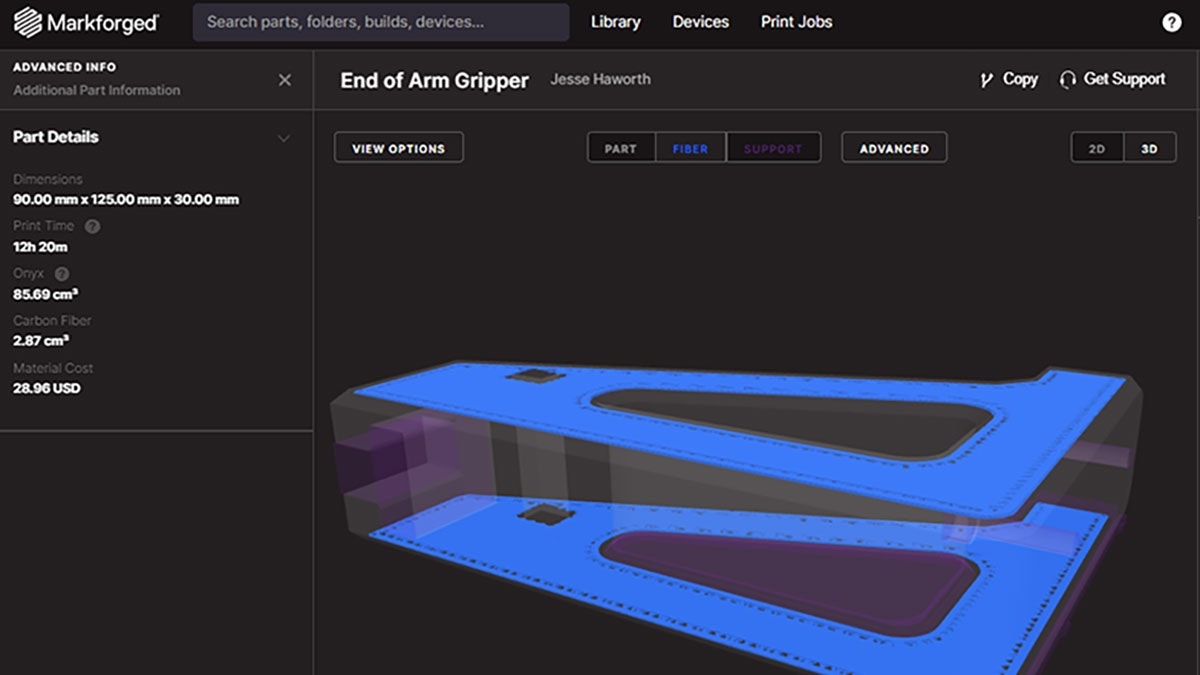
To show how we can use everything covered today, we’ll start with a soft jaw that has been set to have fiber in almost every layer.
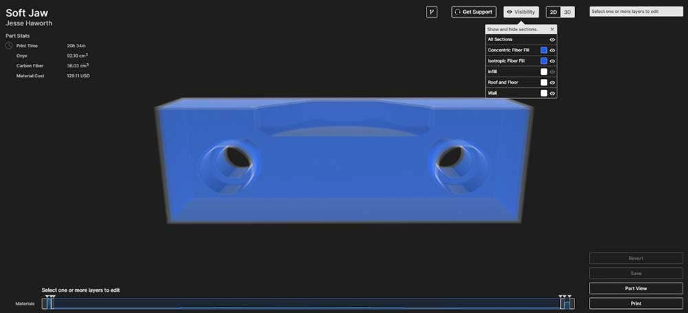
The starting point of our soft jaw, with Carbon Fiber placed in nearly every layer.
There is no doubt that this setup would have significant strength. However, the high amount of Carbon Fiber usage means a higher cost per part, and said cost may not be justified by the potential performance gains of this unoptimized layout.
To begin the optimization process, we’ll first delete all fiber that is within the main body of our part while keeping the top panels. Taking a page from the shelling section, we’ll also place an Isotropic fiber panel below the interfacing feature of our jaw.
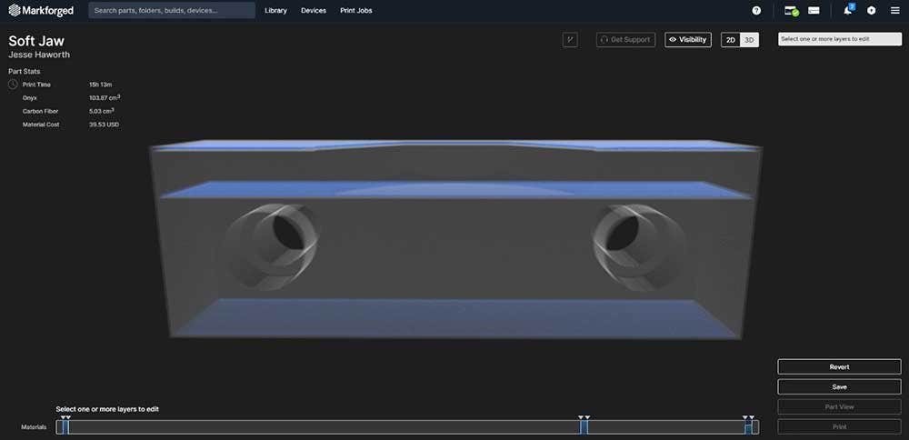
Isotropic panels set up for use with our optimized part.
Next, we’ll look at the areas of our part that need to be reinforced. These will primarily be the bolt holes and our main feature near the top of the part. We’ll reinforce the latter first by setting a group of concentric fiber rings to provide strength against the conformal load that will be present when using our jaw.
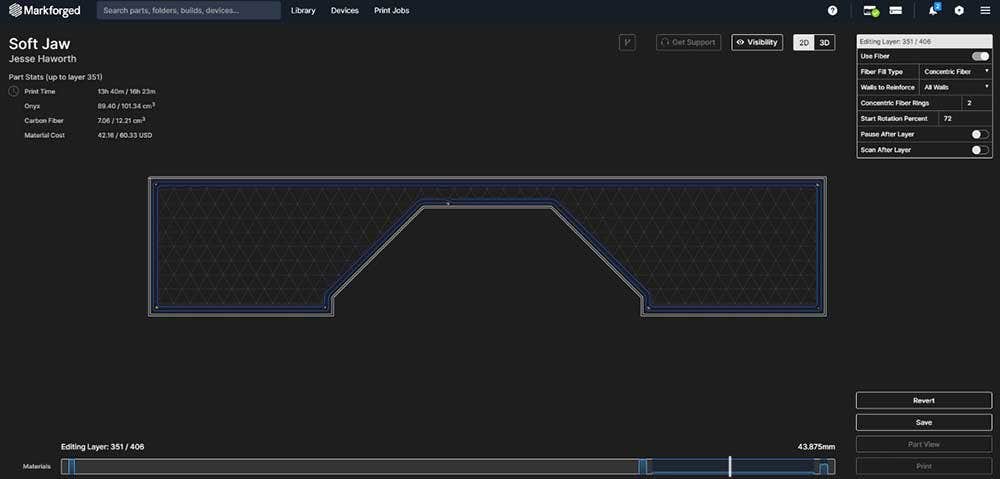
One layer of the Concentric fiber group that reinforces our interfacing geometry.
Lastly, we’ll reinforce the bolt holes by creating a striped fiber group of Concentric fiber. We could set this as a solid group depending on how tightly these will be clamped, but the stripes provide significant strength while reducing cost.
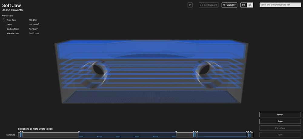
A look at the final optimization of our part.
Since the remaining areas of our part will not be under any significant load, we will leave them without fiber in this layout.
With that, our optimization is complete! Our cost goes from $129 to $79, which is close to a 40 percent reduction. Of course, one main advantage of 3D printing is the ability to get parts out the door quickly and test different iterations. If a printed composite part meets all performance expectations, there may be room to optimize the fiber layout and reduce cost.
Thanks for reading everyone! Check out our site for more information on Markforged 3D printers, and if you have any questions be sure to contact us at Hawk Ridge Systems today.