Sketching is a fundamental aspect of SOLIDWORKS, and any time saved during the process can yield significant dividends. To that end, we have compiled a list of five tips and tricks to help you sketch more efficiently and quickly in SOLIDWORKS.
This content was adapted from a presentation originally delivered at the Western Michigan Lakeshore SOLIDWORKS User Group (WMLSWUG) summit in December of 2022.
Rotating Sketch View to Normal
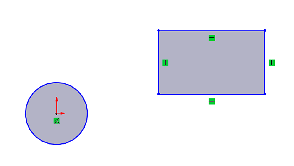
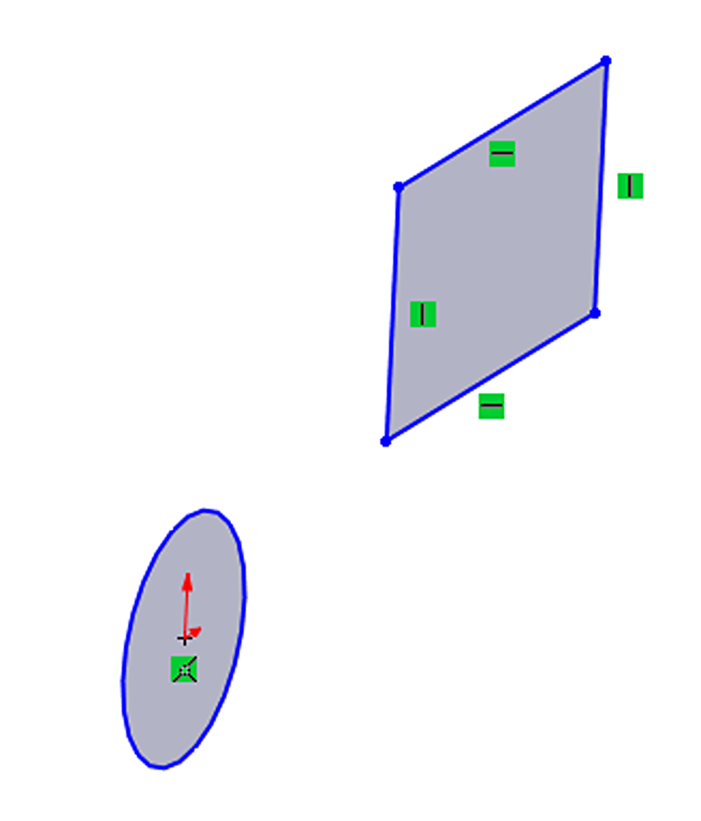
When it comes to sketching, the most optimal camera orientation is normal to the sketch plane. This technique keeps shapes undistorted, making it easier to see the relative distances between sketch entities, and enables drag and drop relations. To illustrate this point, the images in Figures 1 and 2 show the same sketch, first captured from a normal angle and then from a skewed angle.

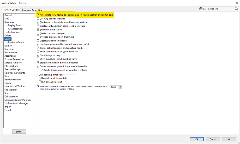
There are two opportunities to control the camera view in the sketch environment. The first method is upon entering the sketch environment through the Options>System Options>Sketch section. Once there, select the option to automatically rotate the camera normal to the sketch plane when creating a new sketch or editing an existing sketch.
The second method involves rotating the camera view away from normal during the sketching process, which may be necessary to attach a relation to an occluded edge of the model or view of non-parallel sketch.
However, after doing this, it is usually best to return to a normal orientation for optimal results. This can be achieved through the view orientation menu, located in the heads-up toolbar, or accessed by pressing the spacebar. Alternatively, the default keyboard shortcut of Ctrl-8 can be used for a faster approach. While there are a vast number of keyboard shortcuts in SOLIDWORKS, Ctrl-8 is one of the most frequently used and should be memorized if possible. It is worth noting that if the view is already normal to the sketch plane and Ctrl-8 is pressed, the camera will rotate to the “back” of the sketch plane, which can also be a useful feature to remember.
*Keyboard shortcuts can be customized in SOLIDWORKS including the view normal command.
Inputting Dimensions While Sketching
Another useful option can be accessed through Options>System Options>Sketch, which enables the creation of dimensions while sketching, rather than having to do so separately after sketch is complete.
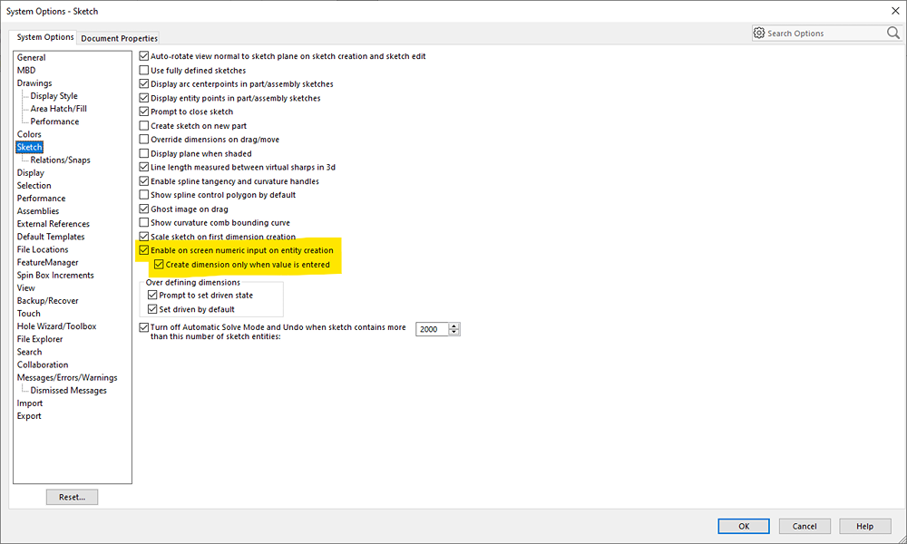
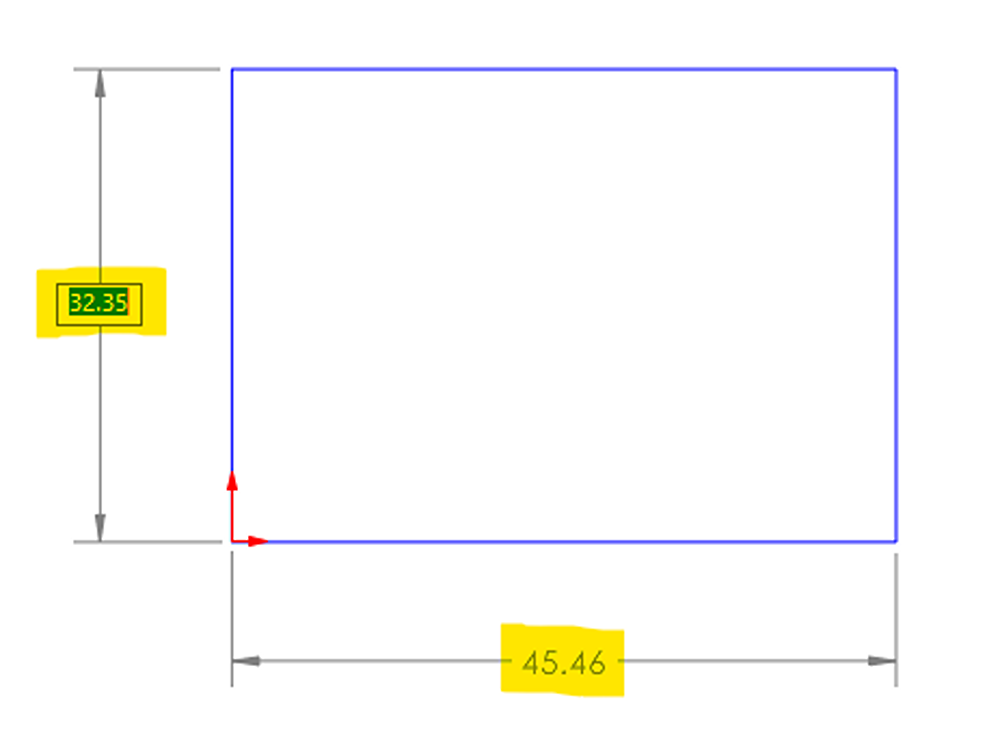
By checking both boxes highlighted in Figure 4, you can produce readouts that display the dimensions of the sketch entity you are creating. For instance, if you are creating a rectangle, it will show the width and height of the shape. Before clicking to complete the entity, the keyboard can be used to directly type in the dimension values. Simply use the tab key to switch between the width and height fields, and then press the enter key to confirm and create the sketch entity along with its dimensions in one single step.
Shaded Sketch Contours
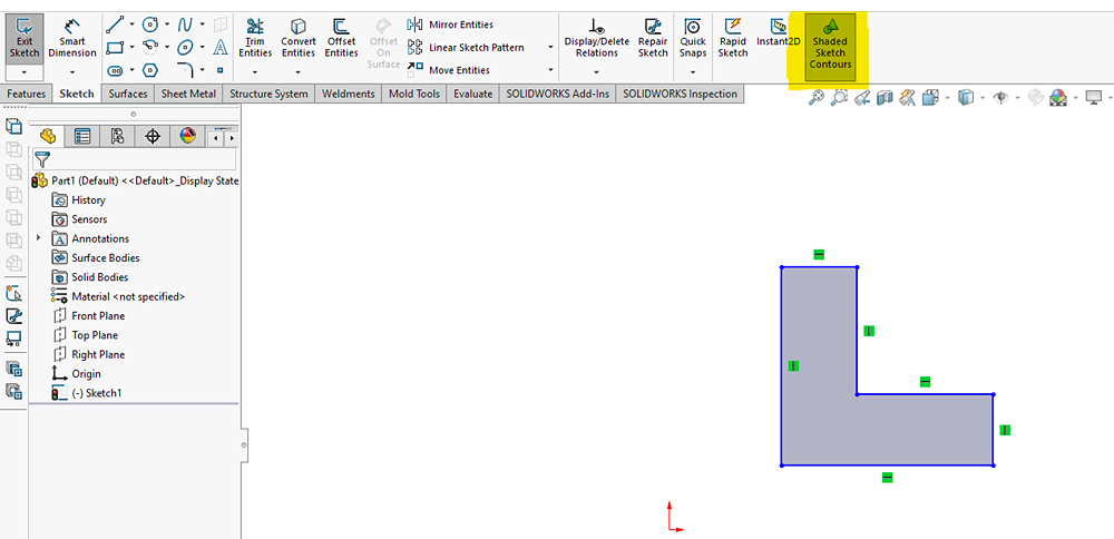
To enable Shaded Sketch Contours, click the button on the right side of the sketch tab in the CommandManager. This feature shades enclosed regions (closed contours) in your sketch, allowing you to quickly identify any small gaps in your closed contour.
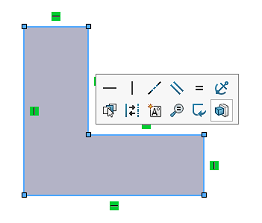
Additionally, by clicking and dragging from the shaded region, you can move the closed contour around your sketch without distorting its shape, even if the contour is not fully defined or locked in place with dimensions or relations. Without the Shaded Sketch Contours option enabled, you would have to perform a box select of all the entities you want to move, which can be tricky in a crowded sketch. Dragging a single entity or vertex would simply resize the shape without moving it.
By clicking in the shaded region, you can automatically select all entities that make up the closed contour. This lets you also run commands like mirror, offset, extrude, and revolve which can be helpful in sketches with multiple closed contours.
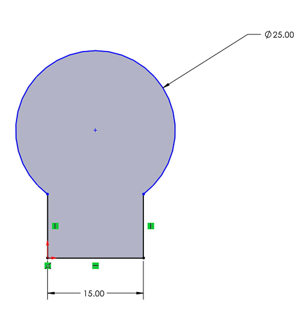
Trim to Construction
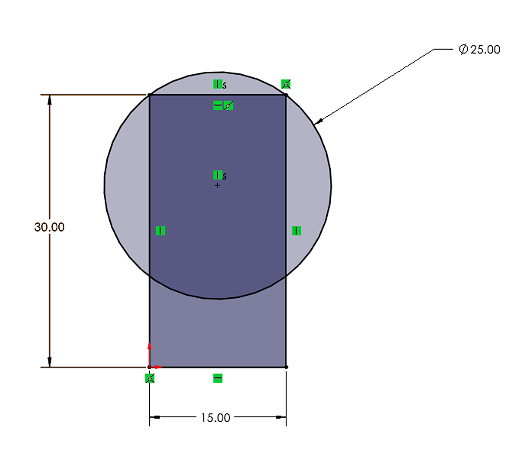
The keyhole shape in Figure 8, is created by combining a rectangle and a circle, and it is currently fully defined. In the following example, we will utilize the trim tool to eliminate any overlapping contours and turn the keyhole into a single, closed contour.
When normally trimming it, certain dimensions and relations may be lost, resulting in an underdefined sketch.
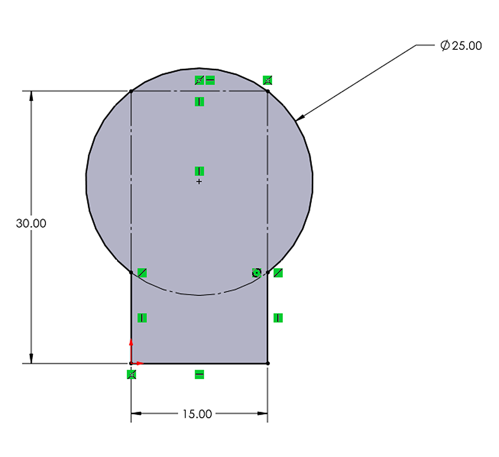
The solution is to enable the option shown below, which converts trimmed entities into construction geometry, rather than removing them entirely.
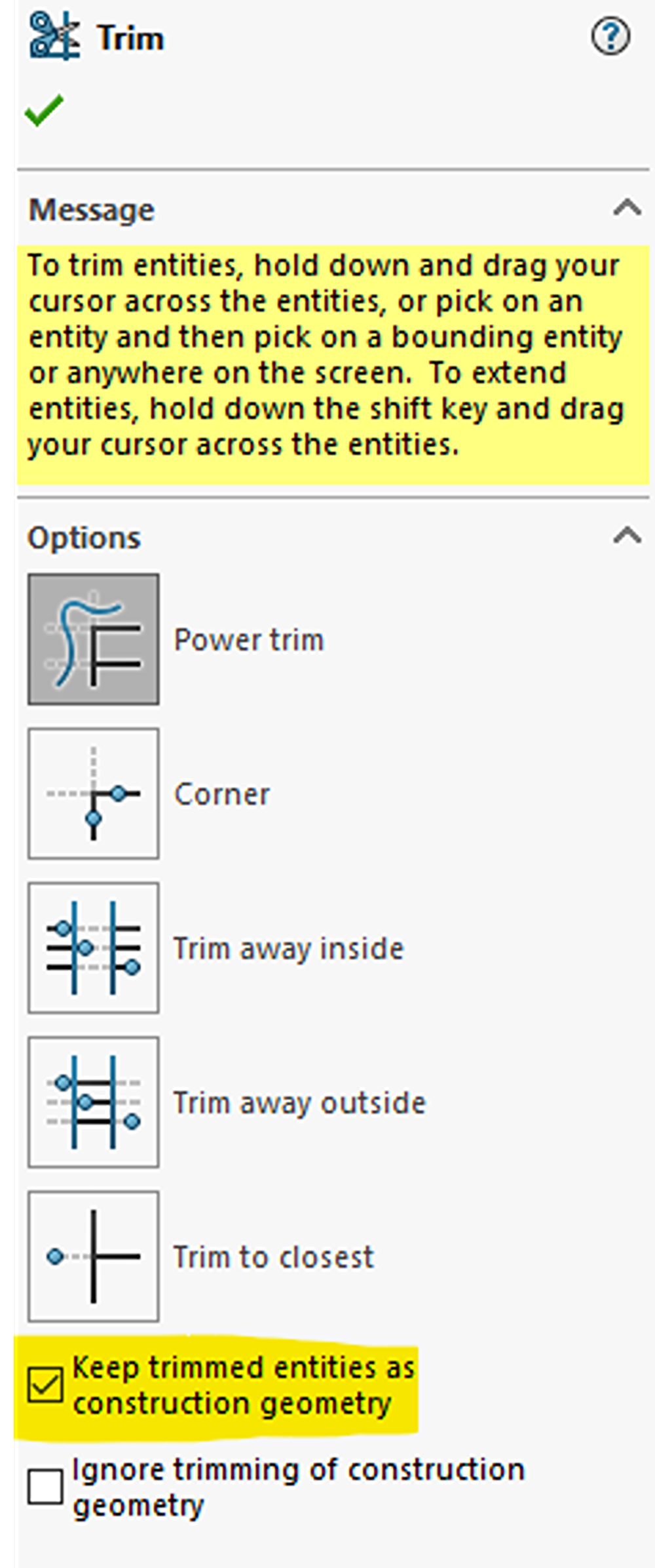
Now, if the sketch is trimmed with the option above enabled, the sketch will remain fully defined because none of the relations or dimensions are removed.
Dynamic Mirroring
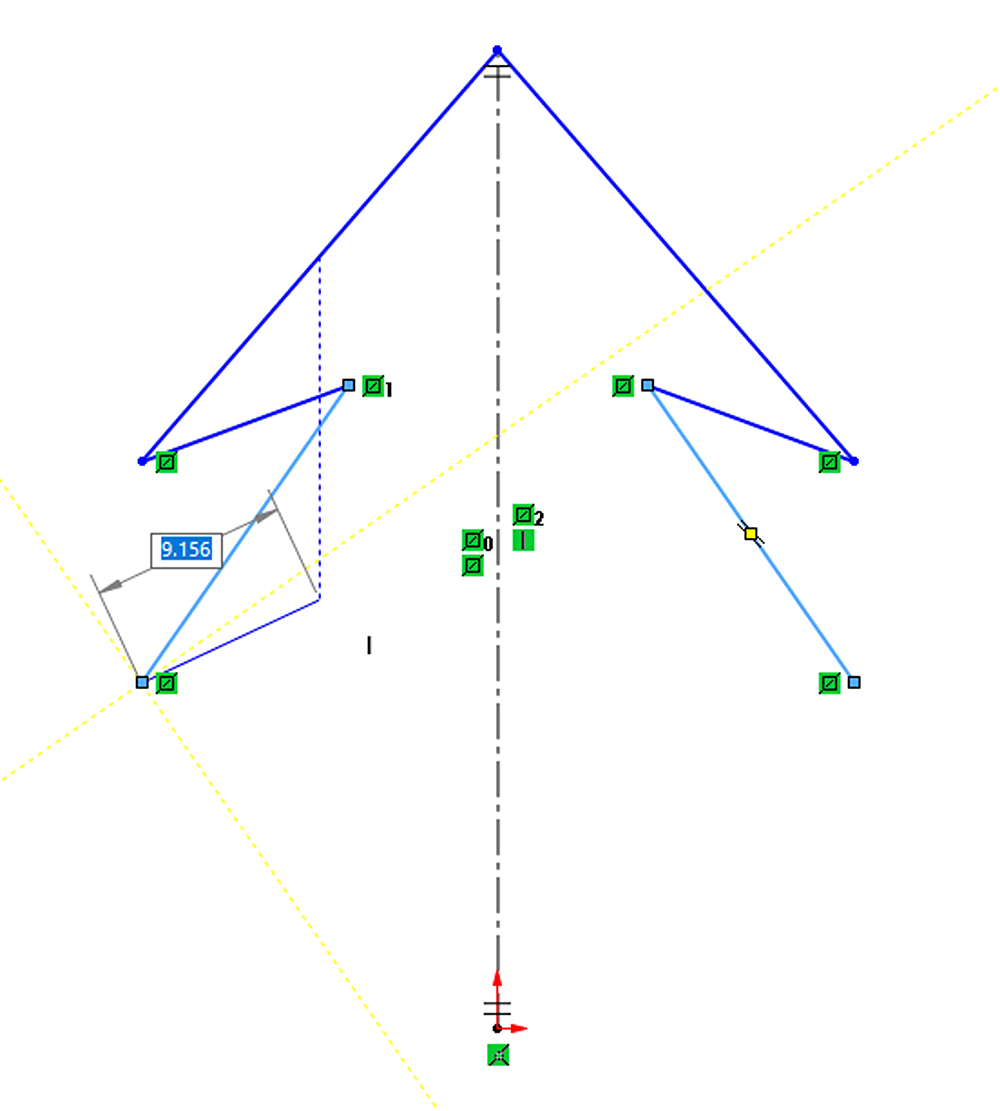
Mirroring is a widely used sketch operation that can be helpful to view the mirrored entities while still sketching the seed entities, rather than waiting until the end to mirror everything at once.
This can be performed by using the Dynamic Mirror tool which is found in Tools>Sketch Tools>Dynamic Mirror or can be searched for by pressing the S key on the keyboard to enter the command search. When the tool is launched, it will prompt you to select a line or edge to mirror about (if one has not been preselected). From there, you can sketch normally, and the mirrored entities will appear after each mouse click.
It is important to note that the dynamic mirror function operates as a toggle. Once the mirroring is complete, it is essential to turn off the tool by clicking on the command again. This can be done either from the menu bar or by searching for it again.
Conclusion
Although these methods will not unlock any new functions, they possess the potential to save you time and reduce the number of mouse clicks needed during your sketching process. Combine this with the widespread use of sketches in SOLIDWORKS, implementing even one or two of these tricks can make a significant difference.
Have questions about these tips or anything else related to SOLIDWORKS? Contact us today!