In the modern world, most products come with an app or some degree of connectivity. You can control your house by voice activation and drive your car or feed your pet from your cell phone. Today’s products are more connected than ever, yet the multi-disciplinary teams that manufacture the products are all too often disconnected. Join us for a look at how the SOLIDWORKS Ecosystem and our partner products are helping to break down the barriers between teams and help build better products that get to market faster. We’ll take a look at the industry trends, the solution as a whole and delve into some of the enhancements in SOLIDWORKS CAM and CAMWorks 2019.
Introduction – What’s New in SOLIDWORKS CAM & CAMWorks
Video Transcript
Agenda
I’m Daniel Lyon and I’m one of the CAM Specialists at Hawk Ridge Systems. Today’s webinar is going to be a bit of a mix of stuff. There will be a little bit about the background about what’s going on in the industry as a whole, you may have heard things like Brexit, Industry 4.0 or I4, that’s the fourth Industrial Revolution, and a bit about an explanation about what’s happening in the industry as a whole. Delving into SOLIDWORKS solution side of it. how SOLIDWORKS is basically partnered with CAMWorks in 2018, how that actually is shifting the industry somewhat.
We’ll look at some of the new functions as well and how SOLIDWORKS and CAMWorks have actually developed things towards that goal of Industry 4.0 and everything else. Lastly, we’ll also look at a new product that Hawk Ridge Systems actually just signed on with this year. It’s not new to us in general. We partnered with Cimtronics Midwest and they were supporting CAMWorks for a long time, but we’re looking at just to introduce a few of you guys to some of maybe the DNC side of things, machine data collection and how that maybe ties into the whole Industry 4.0 system. So with that, we’ll get started here. Essentially the agenda for today is basically looking at the what is going on in the industry as a whole, looking at how SOLIDWORKS is basically changing the way manufacturing occurs and then looking at what’s new in the software for 2019. Essentially, where are we at today? We’ve got a lot of different digitized systems. We’ve got ERP systems for enterprise planning, we’ve got MRP systems for manufacturing, resource planning.
Basically, we’ve got a lot of different digitized systems, a lot of our software these days is keeping us on our computers and our laptops and everything else. We’ve gone away very much so from paper-based systems. CAD obviously and CAM as well being through the other major ones in a manufacturing environment.
Data
With all of that, we’ve got a huge amount of data, we’ve got customer records. We’ve got purchasing records and financial records. We’ve got all of our CAD data, we’ve got all of our simulation data, we’ve got all of our manufacturing data, our setup sheets, our G-Code, a whole bunch of different stuff. Now usually you end up because of all of those different products and often they are separated products, essentially your CAD is in typical fashion these days.
There’s still a lot of people that are using a separate tool or separate software for each of those different solutions. What that usually results in is a whole bunch of meetings where everyone’s going for discussing any potential issues that everyone has to be pulled off of the shop floor pulled out of their office and things like that just to have a meeting and sometimes there are meetings about meetings and everything else and then you’ve got emails in your inbox and it’s pretty overwhelming, just the amount of data and the amount of information it gets thrown at you all of the time.
Industry 4.0
Essentially what Industry 4.0 is trying to do is try and connect machines, people, devices and systems using the internet of things, basically the IoT. With the inter-connectivity between machines, people, systems and everything else, you can garner a lot of data from that. So you can draw all that data into an environment but rather than having to look at some bar chart or spreadsheet or kind of analyze the data that you’re receiving what you want is the right data in front of you and it wants to be real time. It doesn’t want to be a week out of date or two weeks out of date or a month out of date. It needs to be basically right at your fingertips whenever you need it.
Essentially the goal is to have different systems to assist humans and humans to just assist different systems. So basically if there was something like an unpleasant job or just something that isn’t particularly rewarding for the for the operators and thinking something was just difficult or it’s just labor-intensive and things like that, why don’t we get a system in place to be able to take that away from the human and basically put it into an automated fashion and the same goes the opposite way when systems fail or in systems running into an issue, you have to have a human there to know what to do in that situation. So it’s kind of a connection between the way the operators are and the way their machines and devices and systems are right.
The fourth portion really ties back to that meetings point that I just made. When you have a system currently that it’s all this data is coming at you in different spreadsheets, documents and presentations, and meetings, you’re essentially being pulled away from your main purpose unless you’re a manager of doing all that sort of stuff.
Decentralization, essentially what it means is you’ve got a lot of systems in place to manage how those situations occur so if you are running into an issue where production quantities are low, maybe you have an automated system that fires up another line or something like that or maybe you’re overproducing and it shuts down a separate line or something like that, rather than having a meeting to discuss all that, try and have some sort of automated system that goes, “Okay, based on sensors, based on certain inputs and outputs, do this for me.”
Basically in a nutshell what Industry 4.0 is trying to do is trying to integrate processes and systems together, so that everyone is working on the same data, same files using similar systems or something that’s familiar to everybody, automating the difficult unpleasant tasks, taking away that stuff so that we basically become more of a monitoring situation but that frees us up to do more complex stuff.
We also want to give the right data to the right person at the right time. The last thing everyone wants to be doing is running off data that’s months old because you’re not making a decision based on real-time situations and basically the whole goal of it is to use sensors and that data is to drive an automated decision-making process so you can streamline everything.
Now Industry 4.0 really is going to be kind of pushed forward by automotive, aerospace, and high-end medical stuff that’s the typical situation and then it filters downstream to a lot of the mainstream manufacturers as well. But there’s also a huge bunch of other trends that seem to be going on. There’s a lot more what they call onshoring, essentially bringing manufacturing back to North America, back to somewhere closer to you. There’s another term called near-shoring where you’re not using vendors or suppliers, which are right across the other side of the world. You’re using them within a reasonable locale, basically within a reasonable distance, but there’s a lot more manufacturing coming back to the local areas primarily because you want to be more responsive to those needs.
In a situation where that might exempt is like for instance, I have a mold that I’m making. I shipped it out to the Far East. They did all the work for it. They send me all the parts but then there’s an issue with the mold and it comes that I need to change the mold or I need to change the part, which changes the mold and everything else. Well, if I’ve got my manufacturing done in the Far East, I might have 20,000 or 50,000 parts in shipment already on the way to me and then I’ve got 50,000 parts which are basically scrapped, or old, or I have to deal with them somehow, and then you’ve gotta stop production in the Far East. Make your change and then you finally get your changes back, several hundred thousand parts later or whatever. There’s also a trend to sell services rather than products. Obviously, there is always gonna be a market for products. We’re gonna look at an example of a hi-fi.
Rolls Royce used to sell jet engines to people. Now they don’t do that. They sell the hours used and then they basically do all the service work themselves and keep things at the service rather than the product. There’s also a lot of product customization. Things like you can go to the many of the automotive manufacturers these days and ask them for a specific trim, or specific paint job, or all sorts of different stuff. The Henry Ford saying, “Well you can have basically any color you want as long as it’s black.”Well, that’s not the way people buy things these days. People want their own customizations. They want their own special take on some product, and really Industry 4.0 leads towards, “Okay, well how do I get mass production that’s also customizable?” Looking at the car market, essentially they’re doing that right now anyway. There’s also a trend towards cost reduction, some of the big buck stores, and Amazon, and people like that, you’re also setting a precedent with cost. People are expecting things much lower value now, so there’s different cost reduction that may be coming in.
They may be bringing major manufacturers might be bringing manufacturing in-house rather than using a bunch of job shops and things like that, or they put the pressure on their suppliers to kinda squeeze the cost down and things like that. And I saw it, I just kinda take a quick look at cost ’cause cost is one of the biggest driving things. Essentially, the cost of a product is built from the materials that you use, the labor that you have, any overheads, things like utilities, depreciation of machine tools, thing like that, and general supplies that you can’t really attribute to a particular task, and then there’s also a period cost, things like admin expenses, rent for the buildings and office supplies, and things like that, so all of those go together.
Now the factory overheads, you can do some manipulation of the period cost is generally quite fake, but you got materials and labor. Now you can’t really change too much on materials, materials that required for the job or the design need to be those materials and obviously you can go and try and find a slightly cheaper supply of that equipment, material, and purchase that, but then you may run into quality issues and things like that.
Some of the main goals of reducing product cost might be minimized scrap and rework. That’s an easy one to do. Try and find all of your potential for scrap. Where is all your situation? And then also implementing some of the lean manufacturing principles, or just in time practices, things like that, so you can actually try to save on material and storage even, things like warehouses, and warehouse space. All take up certain things.
How can you do just entire practices and things like that?
In terms of labor, salaries really need to be competitive. If you start acting salaries, I’m pretty sure you’re gonna lose, staff pretty quickly, so to keep a good workforce you have to pay them sufficiently, but further to that, you basically to reduce the product cost, you can reduce the product development time.
Product Development Cycle
Now if we look at a typical product development cycle from years gone by, it essentially looks like this, you do your design work, you do simulation, you prototype, you validate it, you revise the model, you go back to a review phase, you go on change the design, you rerun your simulations, you re-prototype, and then you eventually get to manufacturing at the end, and then you may even go through a manufacturing process where, “Okay, well we can’t make this in-house,” so you have to ship it out or we have to basically adjust our parts to make it manufacture-able. So it’s a sequential process, usually involves multiple different software. You could be using a CAD package or simulation package. You’ve got software for prototyping. Then, you’ve got software for manufacturing. All those require multiple different files, different file formats, and everything else. Design changes become problematic because you’ve got to go through that loop all the time. And essentially you can leave the unnecessary outsourcing because you may have designed something that you couldn’t make in-house. You have to ship it outside.
And that last one was really kind of simplified version. Yes, a design is a design but design includes conceptual designing, includes industrial design, mechanical design, electrical design, PCB design, simulation, might have a linear static stress house. You might have non-linear, linear analysis, flow analysis, prototyping, earned validation, may include 3D printing, it may include CNC machining, breadboards and things like that for electronics. You’ve got technical documentation to also produce. You rendering is for marketing material. You have product manuals to produce.
You’ve got inspection documents to create and then you’ve got manufacturing right at the end of it, CNC machines, 3D printing, electronics, and production electronics, and production electrical. And all of that is kind of underlined by TDM and the review process. What the SOLIDWORKS ecosystem is trying to do is trying to condense all that. So we get a shorter product development time and then lower product development cost. Essentially, what we can do is, we need our designs. Our designs are the key things. That’s where SOLIDWORKS bread and butter came from, the CAD side.
They were one of the pioneers of parametric design and basically, since then they’ve been improving on it, improving on it, improving on it, and spreading out into certain different markets. Now, you’ve got Composer and Visualize technical documentation. They’re running the SOLIDWORKS model in a set for the environment so that you can do your technical documentation but still maintain that link to your CAD file. So if there is a change, it propagates through, prototyping and validating the introduced 3D print drivers and things like that a couple of years ago.
There are simulation and tests and things like that. There’s a lot of CAD stuffs that the validation side that isn’t entirely SOLIDWORKS but it ties into the same ecosystem. Simulation, full analysis and everything else, do you run a full analysis and then you realize there’s a rev change or someone changed the cooling fan because they couldn’t find the purchaser or the purchaser couldn’t find the particular spec of fan that they needed, so they change the model which needs different hole positions and things like that, which all goes to change manufacturing data.
And basically, the whole goal of this is to try and get everyone on the same page using the same models and the same environment so it becomes a bit more familiar to everybody. They don’t end up having to learn 15 different software and so that everyone can communicate through each other. So, the way I see it is that is a big ship, SOLIDWORKS design basically taking account system on board and branding it with SOLIDWORKS. They did a huge change with a parametric CAD. They realized the ease of use was number one. You got to get people using it. You got to have people finding it easy to use.
Parametric CAD
And that’s really where SOLIDWORKS strengths boiled down to, it’s ease of use and parametric CAD. Now, they’ve started venturing out. We’ve got parametric CAM. So our CAM data or manufacturing data lies on our SOLIDWORKS model. It doesn’t lie on a third file or a fourth file out of the system somewhere. So we’ve reduced our file counts because we’re not having to have a two paths file, a CAD file, and RG code, we end up with our path file and our RG code. It also promotes collaboration between staff and teams. And what I mean by that is every seat of SOLIDWORKS on subscription in 2018 had CAM enabled and in terms that SOLIDWORKS can understand it.
What that allows engineers to do is understand more of the design of the manufacturing side because I’m sure there’s a lot of people on this webinar that may have come across a part that just wasn’t manufacture-able. It came out of it, the engineering house and basically, there was no way you could produce it. The rides are too small or something was just, you know, square corners and things like that. Having a CAM tool inside of the CAD tool promotes an understanding of the engineering side, so it’s not just a toss it over the fence to the manufacturing team and let them deal with it. It’s more of a team effort to get a product out and because everyone’s working together as a team, you got shorter development times. The other thing that’s changing the game really is because of SOLIDWORKS CAM being integrated into every seat on subscription, you’ve got a CAM tool out there. There’s also this trend of, “Okay, we’re gonna use 3D printers and everything else,” and the CNC machine tools used to cost hundreds of thousands of dollars and they still do, but there’s also a more entry level machines and things like that and those don’t cost a huge amount.
You can bring one of those in-house, start controlling your own manufacturing, controlling your own lead times, controlling your own part quality and cost rather than outsourcing it. And by companies doing that, it changes some of the ways that the industry is set up in terms of job shops. Maybe there’ll be fewer job shops because it’s fewer businesses, so job shops also have to then adapt to the changes. You’ve got to be more efficient, you’ve got to be providing a service quicker, so rather than being late on delivery, be early on delivery and things like that, you need to be changing the game to stay up with everything that’s going on here.
We’re going to look at an example. I recently bought some hi-fi equipment and I was like, “Well that’s a perfect example of multidisciplinary teams.” We’ve got things like the CAD designers, we got industrial designers, we’ve got flow and electronics cooling and things like that. You may have some 3D prints if you’re doing like metal printing of heat sinks and things like that. So we’re going to look at an example of that. You’ve got sheet metal fabrication, you have CNC machining, you’ve got some routing for the woods speakers and things like that. So there’s a whole bunch of different departments involved.
And even just putting the models together for the presentation was difficult. Things like the rads on the sheet metal there, you want to make sure you’ve got a nice clean line and in your finished result, the last thing you want is a big old step change and things like that, the industrial designer will have a fit, but basically your manufacturing data is directly impacting all of those other different things. And typically in an old system, your manufacturing is one of the last things in the process. So by having this and all of your details upfront, you know exactly what tools you can use and what size are you can use, you’re working on the same data. So any changes that do occur basically propagate and you don’t have to reprogram things, deal with revisions as much.
In this particular example, as I mentioned, there may be industrial design, there may bee the mechanical design for the actual housing, there’s PCB design and things like that. You may have stress analysis, it just got certain loads on it. If you’ve got a heavy power supply or something like that that’s pushing down on it, you want to make sure it’s not something super Thin and flimsy sheet metal that’s supporting that. So you might have a stress analysis.
You’ve got cooling and those things run stupidly hot sometimes, some of those MOSFETs and things like that. So you’ve got cooling issues. When you’re doing prototyping, you’ve gotta do sheet metal, you’ve gotta do machining, you’re gotta do your electronics or your breadboards, make sure you’re actually gonna expect the results that you get out of your electronic design.
You’ve got marketing manage images, you’ve got to get the people interested in the product before it’s really developed. Product manuals, so you’re going to supply them with documentation to say how it’s being used and things like that. You got inspection reports to produce for basically checking on manufacturing tolerances and things like that. And then right at the end when we got the CNC machine, 3D printing, and all the electronics production. Go onto the good stuff. What’s new in 2019 in SOLIDWORKS CAM. So I’ve got a couple of spreadsheets here, a couple of a PowerPoint slides here that just highlight some of the key points.
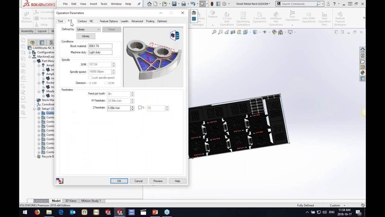
We’ll take a look at them in a second, but essentially one of my favorites is your ability to strategize your machine selection. That for me is huge. For instance, you have sheet metal and we’ve got a laser in the shop. We’ve got a router that’s cutting all the woods for the speakers and we’ve got CNC mills, where it actually smells and things like that. I want to be able to control all of those from one set of setting, or one database. I don’t want to have 15 different databases, everyone wanting their own thing. I want to basically keep everything associated together so that when I select the particular equipment it automatically goes in select strategies associated with that equipment. If we were running into rounding issues on corners and things like that we’re nicking off the corner just because the feed rate changes we can actually now program in slowdowns for corners or AUK moves you can edit the whole condition. Another huge one. If I’m doing all alone, our accountable’s on like an inclined slope.
How do I go on machine nose and stop the drill from wandering, we’ll have to kind of basically put them at the top and do them as a first stop rather than kind of halfway down the slope of the seed machine. So we’ve got the ability now to edit whole conditions. You can now turn on the display of containing and avoid areas. So when you click on the operation it shows you what the void area is or the container it is. There is now functions for long code drilling, but what I mean by that is rather than doing a canned cycle like G-81 or G-82 or G-83, they will output your Z-moves, so, Z-plus, Z-minus, Z-plus, Z-minus that type of thing, but now there is little switching the software is go and, uh, adjust that.
There is an updated edit tool path function. This was one that was hidden, a little bit, not many people knew about it. It’s kind of buried in the old system but they revamped it and put it in a nice little interface. Curve features, we now get CNC compensation control and sham frame, options for curve features as well. You have in SOLIDWORKS CAM if you’re using a professional version you’ve got Vollemil which is now a zigzag function that will basically switch back on itself rather than doing the high speed moves across to the opposite side. And we now have tolerance based machining for turning.
CAMWorks
What’s new in CAMWorks, essentially we now have support for a quad turn, mil turn. Yep, that’s a turn on the left of the top, a turn on the right at the top and a turn on the left on the bottom and a turn on the right at the bottom as well, but we can now have four sets of tools cutting my part.
We can use pinch turning. So we actually have two tools cutting at the same time thing like an OD ruffing or something like that. Running at a much higher feed rate, we have control for a leaf angle now. So rather than Gouch checking on the X and Z plane only, we can actually have a Gouch check in the Y-axis so we can check for tool relief and things like that. There’s a new five-axis, Wallfisch, and Strategy. Vollemil has a zigzag capability in three axes as well as in internal affected. You’ve got rest machining capabilities now as well in Vollemil and three axes and holder checking which is fantastic. And you now have tolerance based machining for mil turn and the new one, one of the big ones is you can actually now purchase an additive manufacturing module as well which will take a quick look at and how that tied into what the industry seems to be calling hybrid manufacturing and things like that. Let’s take a look at some of those.
Now, I’ve got a nest here of the speakers, so this is a router that we’re dealing with here, I’ve just set a few different machines up in my database, so I’ve got maybe a Tormac, a Haas, a router and a laser and I want different strategies for different equipment. I don’t want to be having to constantly switch all my settings around between the different machines.
Now, this is different milling type equipment but the same could be used for mil turns. Say for instance you’ve got a mil turn with the C-axis and a mil turn with the Y axis as well. You might want, let’s say, strategies associated to different types of equipment in terms of the mil turns and so automatically always do three moves on my mil turn, in my Y-Axis machine I will automatically do fixed because I’ve got that Y-axis capability. I can run it across the part and-and go from there. So you can actually save those settings back to the database and reuse them based on the machine specific stuff.
I’ve got mine set up for the router and the key difference in here is you will now see in your database there’s a default feature strategy. So what I’ve done is I’ve basically got a bunch of different strategies which are my default for different equipment. So my default settings are here but I’ve created one I just copied some of the original ones and I went through my database and set my router strategies to automatically do things like a Dedo, interpolate, circular pockets and things like that and chamfer curves and all sorts of different stuff, ramp on the perimeter. My laser equipment, I want to use different strategies, so now I’ve got different strategies that maybe select different curve thicknesses and things like that and then I’ve got my milling strategies which my rough and finish. So this is really where it is and this is how it’s linked to the equipment down at the bottom here. So this is the actual machine that is linked to in your options and the way you set it up is you go into your machine. So if I go into my machine up here, you have this default feature strategy.
So my Haas here might have milling strategies associated to it here, my router has router strategy and my laser has laser strategies all associated but what that means that I can do is running the same database, I can basically hit extract machinable features on here and basically generate router information. So it’s going to use all my strategies, my predefined settings going to generate a program for my router. I was just running the feature recognition, that’s nothing new, we’ve had that for a long time but now it’s doing everything in terms of the way I want to do it on that router.
I can generate my operation plan, generate my tool path and simulate. And now I’ve got router strategies to go on to machine all that stuff out. Alternatively, I’ve got the sheet metal housing is now in here. I might have a laser, I’ve got things like all the sheet metal for the amplifier covers. I’ve got little heat sinks and switch plates and a whole bunch of different stuff in here, so heat sinks there and-and all sorts of different stuff. So what I can do in here is I’ve just set this up to the machine. I’ve already gone into finding the stock and stuff like that in here but essentially I can recognize the features now and it’s automatically going to trigger different laser strategies now.
But again, I don’t have to have separate databases, I can have one database with all of my machines all of my equipment in it and basically program them differently. So basically, that’s a fantastic option that they’ve introduced. It was one of the ones I actually requested which is why I love it so much but we also get that AUK slow down that I mentioned, so in your feed rate controls, if you’re finding that you’re rounding corners and things like that, what you can do is automatically slow your feed rates down in the corners and you can control the angles and stuff like that, but it works too, but it actually run down and slow down a little bit before the corner and then go and change the corner at low feed rate and take back up again to the regular feed.
So now there’s a lot of little slots and pockets and stuff like that, so it looks like it’s still running but it shouldn’t take too long here, way easier than having to deal with a DXF and things like that. I can program routers and lasers and plasma is and all sorts of different stuff on here essentially the software is a milling package but with certain requirements and certain restrictions and things like that, we can certainly run different types of machine tools up there.
So yes, you running the milling package up. You can see is now determining laser strategies for all of these. So I’m-I’m running a tool list, which is basically some smaller sizes of envelopes which essentially represent the curve thickness but now I can go through generate those operations for my laser and running exactly the same thing and that corner slowdown function as Wade expected on the feeds and speeds, you can enable the corner slowdown or the AUK speed rate, so every time it hits an AUK, you can specify the minimum feed rate, maximum feed rate. Or every time it hits a sharp corner, going to reduce, the feed rate is down here to these values down at the bottom and then this is the threshold angles and things like that.
That’s the new AUK slowdown function. What we’re going to look at next is looking at machining the body of this digital streaming unit here. So one of the new things rather than using CD players and everything else these days, everyone’s in the Hi-Fi industry is lensing towards digital streaming, like YouTube and everything else to your phone and running everything off of your phone and everything else. And this is the housing to basically house that sort of stuff so we got some switchgear in it. We’ve got back panel comes in here and things like this. Got some slots for that. We’ve got some slots for things like our cable routing and things like that. Going here, I just ran the feature recognition, did a great job of finding a bunch of different types of features in here. The first thing I wanna show you is whole adjustment options.
Now, this is an example where I could do it after the fact but the difference is I’m dealing with something like this type of geometry where I’ve got a slope here. I’m trying to drill a hole in a slope. I don’t want my drill to wander so often what I used to have to do is have to go in manually create a sketch, put in the sketch at the top of the pot, put it as a whole feature, basically set the depth and everything else and program it like that. What we now have is an option just on the right click menu to edit the end conditions of the holes. So I can actually go in and say, actually rather than going from here, stop from up here so I can now drill it and tap it this full way if I wanted to, and then I don’t have to manually define anything anyway.
Now, this can also be set as an automatic setting in your options menu. So your options menu over here as an option to automatically extend all the holes to the stocks. So if you’re running into this quite a lot, you can check that on, hit apply, automatically get it to switch them all. And you can always just uncheck it and hit apply if you don’t want to occur on a particular file. So you can set your preferences up here to what you find most commonly or you just leave on and leave off and then turn it on whenever you want to use it so.
But we can now address the end conditions, the holes to start at different locations. We go to different locations to reference. If I wanted to drill a hole all the way through my part here because I’m gonna count a ball in the back and I wanna indicate off of that for the next off, I can adjust the line and make that happen automatically using those new functions. So let me just generate the operations for those holes here and you’ll see now that the operations now start drawing from the top of the pot around and down in the pot here. That could be something I wanna make sure I’m doing.
As long as you post a pot that you now have your control for canned cycle outputs in this window here. So I don’t have a post selected right now but basically you’ll have the option to switch for canned cycle output versus non-canned cycle output but obviously, your post needs to actually support that. So once you’ve got your post selected, you’ll have a function down here to say canned cycle output, checkbox or unchecked. Unchecked the output put the Z-moves, check to allow put the relevant canned cycle, things like that.
Now, with this type of geometry, this thing’s about two inches thick, I believe. This type of geometry is quite a deep pocket. There’s a lot of material to remove so rather than using the 2.5 axes, I’m gonna use some three-axis roughing. Well, I’ve gone through and just set up a three-axis roughing strategy that I like to do and in this case, I’m gonna actually rough it three times, big tool, middle tool, small tool and then come back with a finisher. I am going to machine the stuff. So here’s our three operations for our Z-level, for our area clearance. I’m going in with a three-quarter inch tool. I got my volume all piped and checked on.
And you’ll see there are now options in here for holder avoidance. If I don’t have enough reach on my tool because my holder might be coming in to play here so if I go and say, “Okay, my holder isn’t very long. Let’s go and say an inch-and-a-half down here.” We’ll just stick everything as far down as possible. But I turn my holder on, you’ll see what it will do. It will actually go in and, and check whether the holder is gonna collide with the wall and then automatically go and say, “Okay, well I’m not gonna go as deep in that particular region but I’m gonna go deeper where I can do.”
On the floor where there’s a big open space here, I don’t want to just stop right where my holder is, even though my holder’s kinda of machining the wall here. I don’t want it to just stop the disposition of machine everything to that depth just because my tool hasn’t got enough reach. But what it will actually do is it will go in machine it to death where it can do and then it will machine up to basically a point where it will hold their check and now you’ll see it’s not going anywhere near the walls there because my holder would fit in that region, but it’s fine in the middle. So it goes in Russell that material out. So that’s a great new option for the kind of. I’m doing this type of work where you may have short tools just to increase the stiffness, but you want to go in with a volume toolpath. So now you can go in and check the holders.
Let’s just set that back to 2.5 We’ve got a big tool so we’ve got a fair amount of reach on it. And what we’re going to do is come back with our smaller tool in here and there’s a whole bunch of new functions as well that I didn’t mention earlier for things like tapered tool support and barrel tool support and things like that. Basically, you can now add tapered tools, tapered shanks and things like that in here so you get a more accurate representation. But in here, the big one for me is I can now do rest of machining on volume in previous a packages is a previous versions volume and we would always go and just machine to whatever the stock size is, regardless of what you tried to include the best machining on or not.
But now I can factor in all of this stuff in here, go and factor in my previous operation and output another volume ETL tool path based on that, but not actually recalculate my volume on toolpath. It will first calculate my first area clearance. Then it will calculate my secondary area clearance claims to see what the machine and then go and machine any leftover. So in this case, my like three-quarter inch couldn’t get into the corner right down here, it’s a bit too small and it’s actually machining all of that leftover because I didn’t generate full the tool path, but then I’m going and again, and machining the tiny little portions out with a quarter inch tool basically to get my material out of the stuff down here.
So you can now implement three-axis machining, with rest machining on volume three axis, so now it’s going to go through and generate those. Another function of volume that they’ve added, and this ones available in SOLIDWORKS CAM Professional and the volume of 2.5 axes and the volume of three axes is the zigzag function. And I’ll explain a little bit about what that is here. So in here, you’ll see on your clearance tab there’s now the ability to do the zigzag.
Now I’ll show you what it looks like before and we’ll walk through the movements here. So there’s this big sweeping motion here, but then it does a high feed moves back to the beginning of the cut and then re-cuts again, comes back with a high feed move. That high feed move isn’t essentially doing anything, it’s not cutting. So that’s why it’s a high feed move. What the zigzag function will do is it will remove that basically the high feed moves and loop back on itself. So rather than going across the full width of that slot, which is essentially wasted cutting time, you will now get the ability to walk around one-way, loop back on itself and walk around the other way. So you’ll see the movements are okay, here’s my movement forward like it was doing before, now it comes out and then rather than going across the pot, which is a big waste of transition, it actually comes back on itself and cuts back on it.
So it zigzags now back and forth across the cut and here. That’s another new option that’s available in the three-axis and in 2.5 axes. The same checkbox that you would use for your regular zigzag pocket in, pocket out type, things like that. If we look at the front of the unit here, we’ve got a big curved feature right across the front here, and essentially what we’ve got is a 3D curve feature.
Now, we can always put in these before and if we pick on a particular setup, we had the curve feature. That’s nothing new. What’s new in the curve feature is there’s a couple of things actually. We can use a 2.5 axis curve feature. Go ahead and tell it the geometry that I want it to follow along in this case and I can go through with my ducts up accordingly so maybe we’ll just do it, say an eighth of an inch. Work on the option here. Go and use our database saying standard stuff. Go and grab our countersink tool.
What we now have control over is we now have control over the CNC compensation and the toolpath center compensation. So prior to this it was always grayed out. It turned on the compensation for a curve feature, but now I can actually enable it or disable it. In this case, it doesn’t really make any sense in this example, it’s trying to do compensation so it would actually gouge the pot and cut it further out, but what I can do is just turn them off. In this case, I want it center line cut all the way down the middle of the V groove there.
3D Curves
The other thing that’s new to curve features is the ability to turn on the chamfer machining option. So now I can actually on a 3D curve if I’m walking up a pot across a pot and down the pot for a different depths range, for instance, if I got a 3D curve, I can now do chamfering on the 3D curve. This option was previously grayed out. In this case it doesn’t really make much sense in this particular example, but I can then go in and I’ll turn this on and specify the length of my chamfer, specify the clearance off the tip and tell it that I’m programming the shop, the virtual shop or the outer edge of the geometry.
There’s also an avoid allowance so you can tell it basically if you want to avoid a certain amount of material. If you want to kind of pull it away from certain geometry, you can turn that on as well. Well, that’s the current features in here, like I said, the main difficulties in this particular part when you’re modeling things like the radius in here, you want to make sure those red rods and things like that are consistent across the board. You don’t want things looking different from different models and versions of your pot and things like that.
All of the design and the way that each of the individual paths intersect each other, like the back plate across here and they meet up perfectly with this and everything else that some of the tricky challenges of this in the design side of it and by doing this in working through different iterations and things like that of your design, you end up changing your model and you may end up with things that might need to be five-axis machines.
Now, five-axis machining can be difficult. In this case, what we’re going to do is put in a couple of swap machine tool paths here to go and cut these two chamfers on industrial designer went and said, “Okay, well I want a big old chamfer on the front and make it looks a bit more decorative.” That’s great, maybe we didn’t have a five-axis machine. So okay, we looked at it, we scope it out, we don’t see that it’s that expensive these days. We go and buy one so we can bring this in-house.
What we can do in here is going and put in our features to go on the machine so I’m going to grab that. I’m going to use a standard five-axis strategy to go and a machine that, and we’ll do the same for our bottom one here as well. We’re going to generate our operations for those and you’ll see the new function is on the panel tab at the top here. So I’m going to just switch over to a flat end mill, in this case, we’re just going to run a 12 machining class right down here. So we’re putting it in the machine in this orientation, but on the panel tab you’ll see, rather than before I had to go to my tilted relate to cutting direction, going specify my tilt angles, go to my panel tab and specify probably flow line between curves or flow line between surfaces and everything else.
In this case, our new swath milling function, we go and tell it what our upper curve is. So in this case, my upper curve is this one. My lower curve is this one. If I make a mistake, I can easily just check the box and we’ll switch them around for me, and it goes into machines are a curve there using swath machine. Same thing with this one on our top of our geometry here. Just basically go in, push it over to swath, and you can’t really get much easier than that in terms of five-axis machining, select two curves and you’re done. Super quick to generate. And here’s my five-axis toolpath to go and machine with all of its booking capabilities and everything else. So super easy to do nice new features and you’ve got now more control over their stuff as well on the bottom here. Things like machining flaw features as well, and things like that so nice new option there.
Differences where we’re developing our new product line, we’ve realized is an issue maybe with some of the interconnects that we’ve been using in the past, we realized there’s a bunch of VMI or a bunch of issues with them. So we want to go and develop our own different binding posts for our equipment. I’ve been through here, programmed this and set it up.
We’ve got our threading coming in, we’ve got our entire process. It doesn’t transfer over to the sub spindle. Basically, that’s nothing new. What’s new is the ability to specify multiple turrets. So we used to have turrets, we had an upper and a lower turret, but when you’re talking about high volume production items like this, where you’ve got tiny little pieces and to connect stuff, all that type of thing, things that need to cost pence to make rather than dollars, you want to maximize efficiency using things like Swiss machines and quad turret machines to basically crank these pots out as fast as you can.
So in your tool crib now, you’ll have now up to four tool cribs. So one for the upper left turret, one for the upper right turret, one for the lower left turret, and one for the lower right turret. And essentially the simplicity of it, programming in here is we just go and select a tool from my tool crib and specified the holder orientation. So our tool crib now as an option appears to say which tool crib we actually are using on which turret. And then obviously our holder orientations will dictate what orientation that we’re using for machining.
So this is the rear on the main spindle. This is our rear on our front spindle. On our front turret basically, there’s the main spindle. So this is coming in from the bottom and machining up. We have now our sync manager as well. Also, this was nothing new. We had a sync manager, but our sync manager can now synchronize those four turrets so that we can go and okay. Synchronize the rear turret near the main spindle and the front turret near the main spindle so that we’re basically cutting the groove at exactly the same time but we’re not wasting time, running separate operations and we’re basically kind of maximizing two tools at the same time cutting.
And then we’re doing our synchronization down here for grooving as well with the rear turret on the front turret for the subspindle at the same time as well. And we’ve got our weight codes in here to synchronize all that stuff, so. And we also have our time view for the main spindle and you’ll see the rear one, the front one, rear two, front two turrets and where the overlaps occur and things like that.
So the other things we can do now are pinch turning. So if say for instance I’m doing this OD profile, you program it exactly the same way, but now you’ll see this and it looks exactly the same way. You’ll now see this simultaneous pinch machining option here. What that will do is when you turn that option on, it will load up two sets of tools in here.
So you’ve got tool one, tool two with each of them, each of the ones in here. So I selected tool, the bottom tool for my front turret and tool one is my basically my rear turret. So basically coming in together, machining these at the same time, roughing this out, and the benefit of pinch turning as you can crank up the feed rates.
Basically, you can double the feed rates because I’ve got two tools cutting at once rather than just one tool going at one time. So you can see now in this case, assimilate this year, you can see the two tools coming in basically at the same time to go and machine that particular pot right down. So we can crank up the feed rate to get these cycle times way down so we can save our cost.
The other thing that we have in our tooling is like I mentioned before, we have a relief angle. So before when you’re looking at your tools, we really just used an X-X and Z profile, so our tools never had a relief angle on them, but you’ll now see on your inserts, you now have a relief angle. So you can actually specify relief angles and make sure you’re not gouging with the leading edge or something like that. So you now you can see the insert is actually tapered now so I can actually go check with those as well and make sure that I’m cutting properly and treating my tools exactly as they are in the machine rather than just as kind of simple 2D shapes. So we now have that relief angle.
So that’s some of the new enhancements in turn. Lastly, we’ve got a new tool called additive manufacturing. Now, this is going to be a new module that you can purchase. Essentially what this additive manufacturing software is going to do is there’s a big trend in the industry towards 3D printers. 3D printers can now print metal. Those metal printed pots may need high tolerance holes. They may need surface finishes and stuff like that. If this was a heat exchanger or a heat sink for example. With 3D printing metal, I can get my cooling qualities, I can get more complex geometry, so I might be able to package things a lot more densely because I can boost the efficiency of my heatsinks and things like that.
Materialise
So what Tamarix has done is basically partnered with Materialise. Now Materialise, they basically have a bunch of additive manufacturing processors. So build a processor to additive manufacturing is essentially like a post processor to-to g-code. It’s basically what translates that particular geometry on the screen in here to the 3D print code that, that particular printer needs.
Now I’ve been through and set this up, it takes a little bit of time to run through, but basically what I’m doing is I’m programming, in this case a support material, so I’ve got my print bed here so I’m going to go and print this one, but I’ve put in a raft, I just lifted up a little bit off the table here, put some support features in there just so that I’ve got my finished face and stuff like that. When I put this online specs and things like that, I want the heat transfer to be as best as it possibly can be and the conduction as good as possible.
3D Printers
And I don’t want a kind of a rough face down at the bottom there. I want a nice clean machine to face to transfer my heat. So what I’ve done is I’ve lifted the pot up a little bit and you can program all the support structures. So what Materialise is doing is essentially allowing you to program 3D printers from one interface, even though you might be running it on many different 3D printers.
You might have a mock forge metal acts and that type of thing through the printers. We have and we sell basically are those three types. Now you might have multiple different 3D printers in your facility. You might want to basically run the same code but on different printers. Essentially that’s what our canned tools do for our CNC equipment. Basically, that’s what Materialise is doing in here. You have one method of setting the print job up, but you’re outputting into multiple different 3D printers based on the build processor but basically the post processor for the actual g-code type thing.
We’ve planned how are we going to print it. We laid on the bed, we’ve oriented it with added our support material and in this case, I didn’t worry about too much the little undercuts in here. It would have done those as well if I wanted it to kind of pull that material beneath these, but I just wanted to on the bottom here, and what I’ve got here is now we have this town works machining option, which will immediately transfer the stock over to my CNC tool. So my stock now is set to an STL file, which is the SDL that I would have been basically printing on my 3D printer.
Basically in here, I’ve got my STL file set automatically over here and what I’ve done is I’ve just run a face feature across the top over here to clean up that, but now I can actually simulate that and I’m machining additive pots basically so I’m doing a hybrid of the two. I’m a machining 3D printed or hybrid machine parts. That’s what the new Tamarix additive manufacturing module will do.
I can now basically go and 3D print into the machine and one software essentially. Keeping everything in the environment here. My bid is set to blow for some reason. But tying into that and Industry 4.0, Hawk Ridge System decides to partner with Predator CNC software and a few of the functions are DNC. You no longer have a guy running with USP staff across the shop floor, they can actually set up all the machines wired and wireless and just send the files or call the programs from the CNC, but essentially to have manufacturing data is critical to this whole process of how much does everything cost?
Because you’ve got things like cycle times, how much is your machine time down? Now what a lot of the big automotive shops have and some of the high-end machine shops have, they have screens on their wall showing live production data. Basically all the data being kind of captured from the scene seaming machines and basically put into high shot spreadsheets and dialogues and things like that on the shop floor so you know exactly where you’re at for the day and what production is actually can quickly glance, see where you’re at, if you need to make changes and adjust your production strategy then you can do so based on real-time data.
But when do you need to replace your machine? How do you know if your CNC machine is comfortably in tear down because it’s broken or something like that? At what point is it now no longer economically viable to keep running that machine and it’s taking you more money and time to fix than it is to actually cut pot.
That’s the stuff that collecting machine data can give you. The other thing may be is that you might have an operator that’s potentially lying to you about, and blaming the machine for this and this and this. How do you know if it’s a machine issue or if it’s an operator issue? Perhaps the operator may need more training, maybe they’re not familiar with that control, but he was kind of familiar with a similar control, but he’s struggling with it and cycle times are down and setup time’s taking longer and things like that. How can you get that information?
Now some of you may not know that your CNC tools are actually bilingual and maybe trilingual. So obviously we can run g-codes and things like that, but there’s actually another language in the background that machine tools can read. So there’s been a kind of industry direction towards well how can we get that machining data off of with the machine? So if you looked at anything like the CELOS control for the DMG machines where they got the CELOS control in the background they got the CELOS interface for all that sort of stuff.
Essentially that is the same thing, but we can actually apply it to all different machine tools using Predator. There’s a couple of industry standard ones where NT support a couple and there are a couple other ones, but essentially what it allows to do is collect data from the machine. When did the operator push cycle stop? Running into startup mode and things like that and he can have a little tablet or you can have a screen or a computer. His station that goes okay, I’m now and set up, he hits that button or his the barcode and it reads all the data into the software, so he knows exactly what he’s programming at any one time.
All of that can actually be fed back into Predator so that you can actually tell what the live data is, what the data is coming off the machines. There’s a touch HMI interface that allows you to have like a tablet and you can go okay, automatically do a bunch of functions when I hit this little button on the tablet. There’s a tool tracker, so you can track, tool gauges and things like that.
Rather than having a guy that’s wandering around the shop looking for a particular tool because another guy just took it out and started using it for no reason, you can actually scan barcodes on tooling and things like that, have it read into the software so it knows exactly where that tool is, where it’s being used and everything else. The DNC sites allow you to call up programs from the CNC machine itself so you don’t end up having a guy walking between buildings or spending time wasting basically your hourly rate walking between the office and the machine. You can have the guy at the machine doing his job and he can just call the program from the CNC or he can go to the office and send it to the CNC rather than having to walk over to the USD. There’s also the CNC editor, that’s the most common one.
Basically, you can go through and edit your g-code. CAMWorks has the NC editor as well. Basically the same code all CAMWorks have the same NC editor as well, but that DNC function really takes it to the next level and you can store all of this and Predator PDM which is basically a way of storing all of your manufacturing data. What tools you’re using? You start up sheet’s, your programs and everything else. Everything can be revision control together in one system and with that, that’s the end of the webinar.