What is Weld Distortion?
Understanding how welded joints will behave under loads is necessary during a design process, considering they are a common failure point. When using an FEA package to find stresses on a welded connection, these stresses appear because of forces applied.
SOLIDWORKS Simulation has tools like the “edge weld connector” (available in SOLIDWORKS Simulation Premium) that can estimate the appropriate size of a weld based on these forces. What is not taken into consideration is how the metal will expand and contract during the heating and cooling cycle of the welding process itself. This means that welded components can fail to maintain their original shape and the welding process can result in shrinkage, angular movement, or buckling. The following article will show you how to estimate these deflections caused by the weld and give you the ability to plan your fixtures and weld path accordingly.
Before we get started, there are a few key pieces of information you need to know before we can begin the simulation. These are:
- The material of the welded bodies with their material properties (most common materials are included in the SOLIDWORKS material library)
- Length and starting location of the weld path
- Weld speed
- Temperature of the weld
Case Study: Simulating Weld Distortion on a Pipe Welded into a Sheet Metal Body
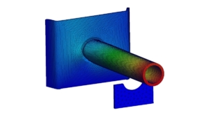
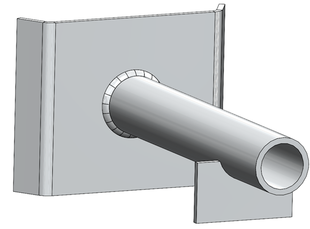
For this case study, we’ll weld a pipe into a sheet metal body that has an open hole to accept it as well as a fixture to prevent the free end of the pipe from falling while it is being welded. The overall model is shown above in Figure 1. The steps of this study are as follows:
- Accurately model the geometry.
- Run a transient thermal study to account for the rapid thermal changes during the welding process.
- Run a non-linear static study, using the results of the thermal study, to show deflections.
Accurately Modeling Geometry
Before running the thermal study, ensure that the model is a good representation of real life. This includes accounting for a small gap between the pipe and sheet metal body, creating a weld body that penetrates both the pipe and the sheet metal body, then finally splitting the weld body up into a certain number of components based on the time it takes to complete the weld.
1. Creating a Clearance Gap
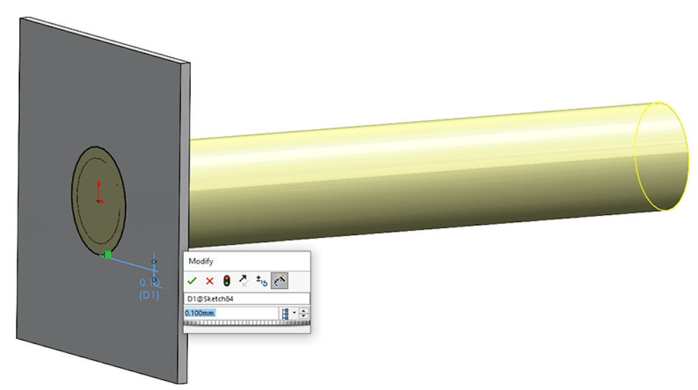
A clearance gap can be created in several different ways. The way we did it in this study was to first extrude the pipe out from the back face of the sheet metal body, then create a sketch on that same back face and use the “offset entities” command to create a projection of the pipe with an added clearance of 0.1mm. Then, we used that sketch to only remove material from the sheet metal body. See Figure 2 below for a picture of the offset sketch.
2. Modeling the Weld Body
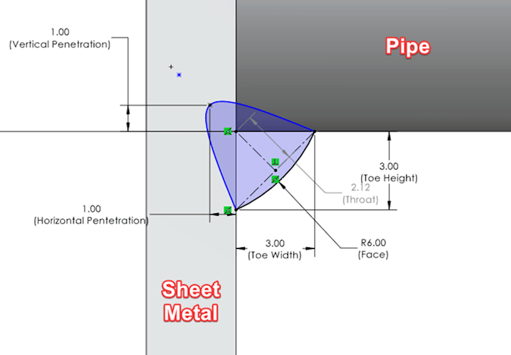
The point of this case study is to try and accurately represent the real-life weld as closely as possible, so the next step is modeling the weld bead. This is done by first creating a sketch on a plane that cuts through the center of the pipe where it meets the sheet metal body, then inputting the weld parameters. I used the conic sketch tool and the 3-point arc tool to create the sketch shown below in Figure 3.
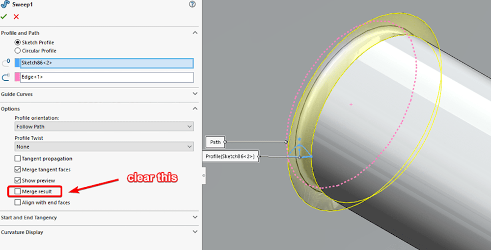
Once you’ve completed the sketch, the next step is to use it for a swept cut, then swept extrusion along the weld path. When creating the swept extrusion of the weld, make sure to clear the option to “Merge result.” You want this as its own body. See Figure 4 below.
3. Splitting the Weld Body into Time Segments
The thermal study in SOLIDWORKS Simulation has a few limitations, and one of those is that heat loads cannot move between different areas of a part. The workaround for this is split it up into segments based on your weld speed weld length. The circumference of the pipe is 105mm (this will be the weld length), and my assumed weld speed is 300mm/min. To get the overall weld time in seconds, divide the weld length by the weld speed, then multiply by 60. Based on those values, this case study’s weld time equates to 21 seconds. See the equation below:

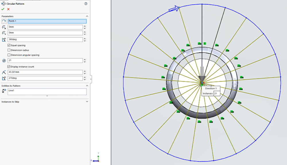
Now I’ll split the weld into 21 separate bodies that each represent 1 second of the weld time. Like most tasks in SOLIDWORKS, this can be done in several different ways. I created a sketch normal to the sheet metal body, then just drew a line straight up from the center of the pipe and used the circular sketch pattern command to create 21 evenly spaced instances of the sketch line. See Figure 5 below:
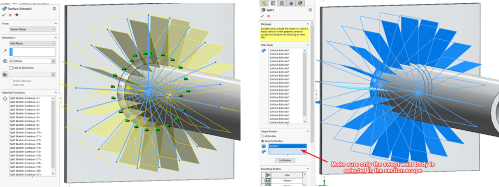
That sketch was used to extrude 21 surfaces, and those surfaces were then used in the “split” command, to break the weld body into 21 sections. See Figure 6 below:
And we’re done! Well, we’re done modeling the weld. You should also add other geometry that is being used to restrain the model during the weld so that we can see how the jigs will affect the distortion.
Transient Thermal Study
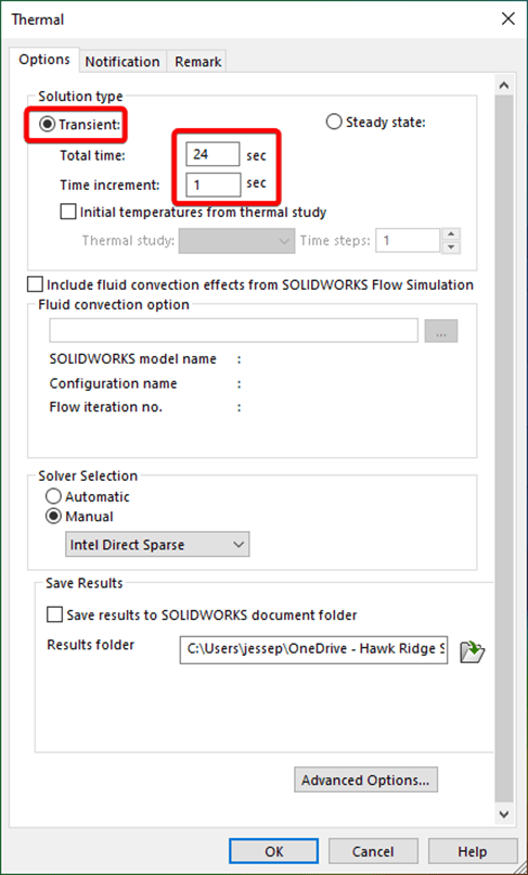
Now that the model has been finished, it’s time to move on to the next step of this process which is setting up and running a transient thermal study. The next step is to define the thermal study as transient and input the study time length. I determined that the weld would take 21 seconds, so to allow for a few seconds of cool down, I input a time of 24 seconds total. I also specified a temp increment of 1 second and chose the Intel Direct Sparse as the solver. See Figure 8 below:
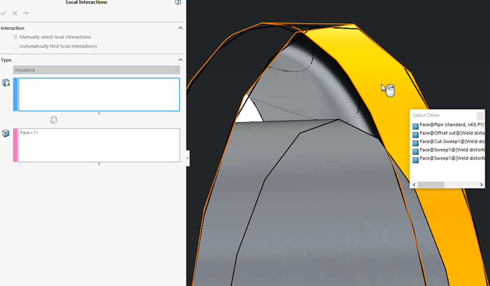
The next step in any study is defining the materials. I’m using Al 1060 Alloy for all components (including the weld beads) for this case study. Once you’ve settled on your material choices, you’ll need to set up the interactions. There is a global bonded interaction created by default (leave this alone.) The only local interaction that needs to be applied is an insulated one between the outer face of the pipe and the inner face of the sheet metal body’s hole. These selections can be hard to make because they are essentially two faces right on top of each other. The “select other” tool is a great way to make the appropriate selections. See Figure 9 below:
Next, apply an initial temperate to all bodies except for the sectioned weld beads. I chose to use 25o Celsius as my initial temperate. Remember to select the bodies using the flyout tree rather than just clicking on their faces, this way the temperature propagates through the bodies. Otherwise, SOLIDWORKS assumes an internal body temperature of 0o Kelvin. See Figure 10 below:
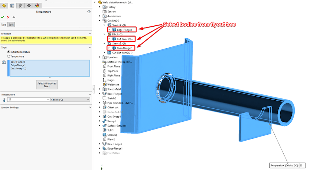
Now you’ll need to set up the weld path temperatures. To do this, you need to know the weld temperature in degrees Kelvin. This study assumes a weld temperature of 800° F, which translates to 699.81° K.
You also need to find where the initial temperature falls relative to that temp on the Kelvin scale. If you assume an initial temperature for all bodies at 25° C, that is 298.15° K. Dividing our initial Kelvin temp by our assumed welding temperature (298.15/699.81), we get a value of 0.43.
This value needs to be used in setting up the time curves for each individual weld body. Also, you need to know where the weld will start and end. Once you’ve calculated these values and determined where your weld will start, apply a temperature load to that specific weld body. Input your weld temperature in degrees Kelvin, select the “Variation with Time” option, then click “edit” to input the time curve.
The curve needs to specify an initial temp (this will be the same for all weld bead bodies), a start/end time for the weld, and a final temperature. For the first weld section equation, the initial time(X) is set to 0, and the initial temperature(Y) is set to 0.43. That is so our initial temperature is assumed to be 25° C. Our weld will start at 1 sec, and we can set the temperature curve to 1(Y axis) so that the body is at weld temp. Finally, specify an end time of the weld (2 seconds) and place the temp value back to 0.43. See Figure 11 for an example of how this was set up.
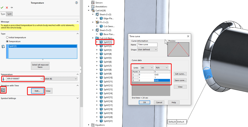
You’ll need to do the same thing for each subsequent body, making sure you are selecting them in order so that they follow the weld path. For each subsequent time curve, the start time will remain at 0 seconds and the start temperature ratio will remain at 0.43, but the next input will increase by 1 second.
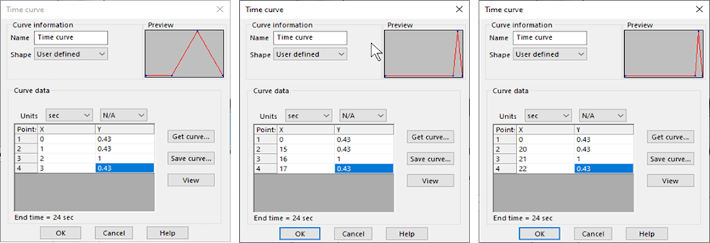
Remember, each thermal load should only be associated with a single weld bead body, and those bodies need to be selected in order of the intended weld path. The last load you need to apply is convection to represent ambient air. Because we used solid elements, we can take advantage of the “select all exposed faces” option in the convection property manager. I assumed a 5W/(m2*K) convection coefficient to represent ambient air and a bulk ambient temperature of 298oK. See Figure 13 below:
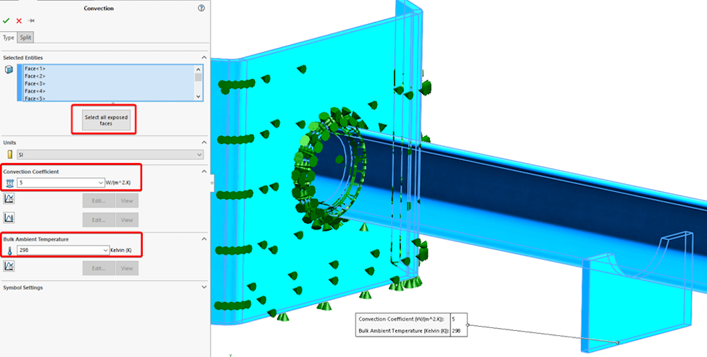
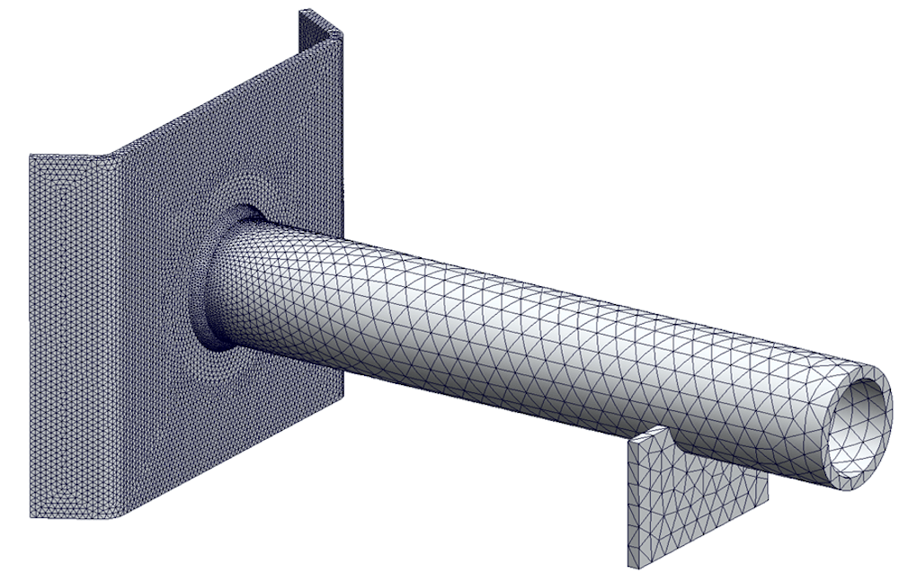
The next two steps are to mesh and run the study. The mesh parameters are going to be different for every situation, but the idea is to try and make it fine in areas of interest, and coarse in areas that we do not need to study.
This study is going to focus on the weld region and the sheet metal body, so I made sure that the sheet metal body had at least 2 high-quality elements going through its thickness, and that the finest mesh was focused on the weld area itself. I also applied a very coarse mesh to the end of the pipe and to the fixture because there are assumed to be little to no stresses in those regions. The mesh used in this study is shown below in Figure 14:
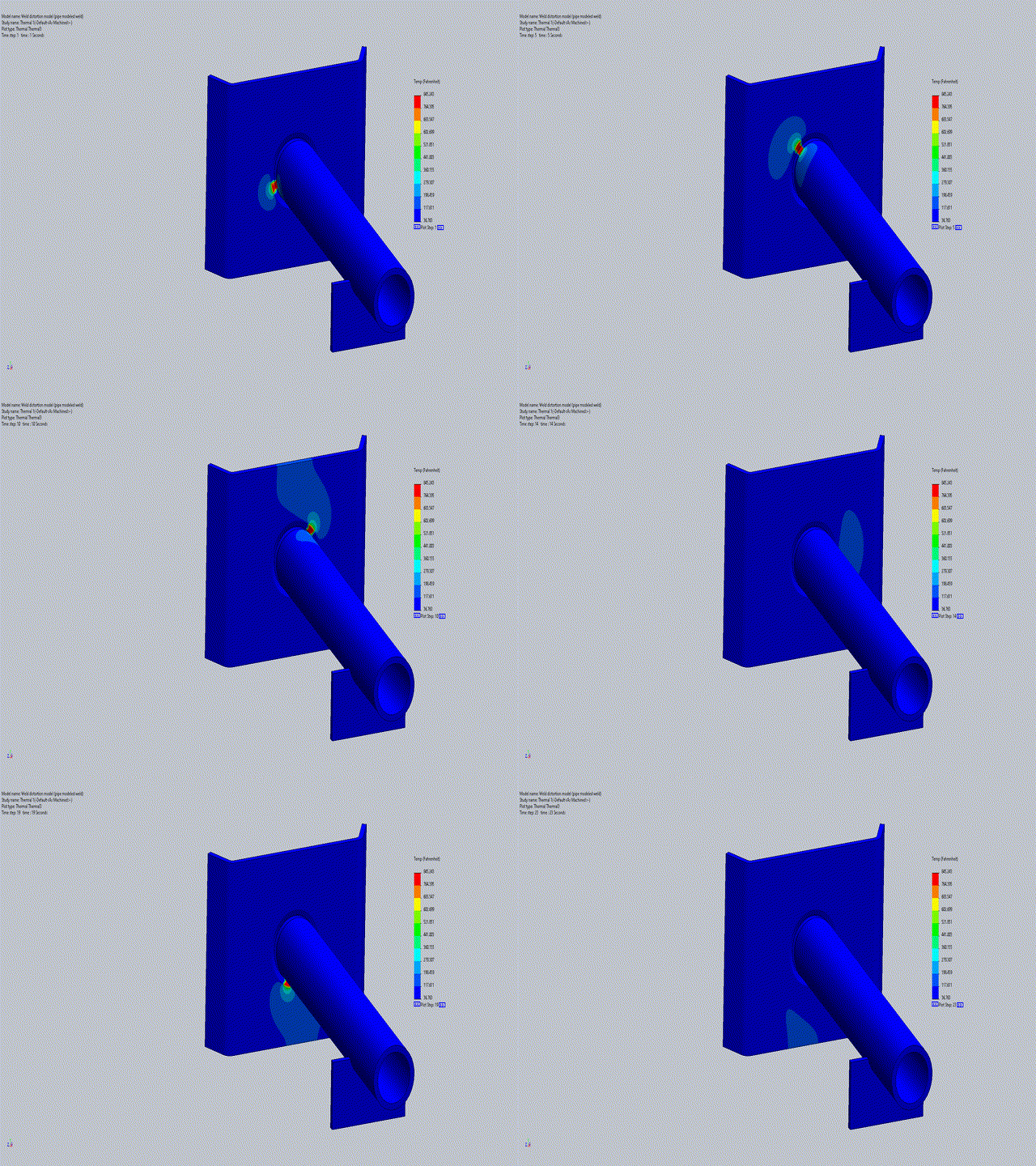
Now you can run the thermal study. Below in Figure 15 you can see an animation of my thermal plot on all bodies except the weld bead.
Nonlinear Static Study
The next step is to run a nonlinear static study using the results from the thermal analysis (this requires SOLIDWORKS Simulation Premium. First, create a new non-linear static study, then you can re-use your parts folder and mesh folder so that you do not need to redefine them. This can be done by just clicking and dragging those folders from the thermal study into the new nonlinear study.
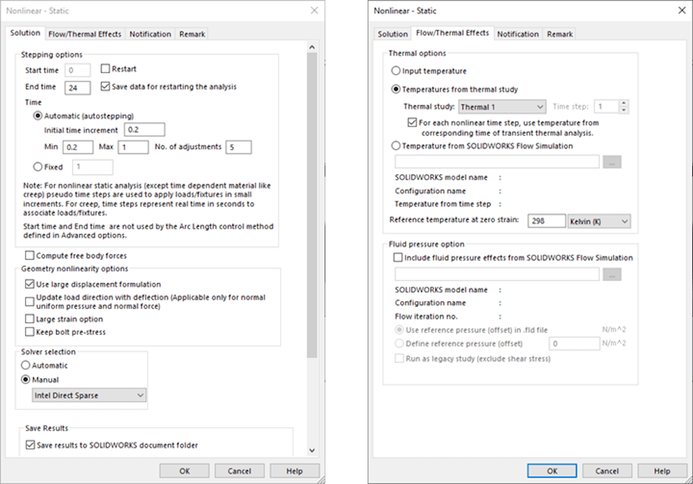
Next, set up the study properties. Right-click the nonlinear study at the top of the simulation tree and select “properties.” Make sure the solution has the same start and end times as the thermal study, and that you are using the thermal solution in your new static analysis.
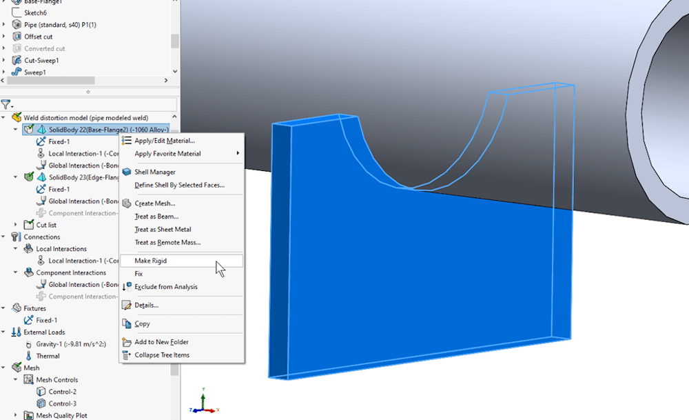
Now you need to define your connections. If there are any bodies that are holding your component in place, you should set them to “rigid” and define a local contact interaction. Figure 17 shows how to make a body rigid, and Figure 18 shows how to set up the local contact interaction.
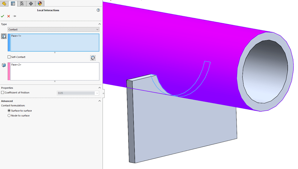
You can keep the global bonded interaction as-is. If the weight of your components is substantial, it could be a good idea to apply a gravity load as well. Finally, apply any fixtures to define how your components will be supported, and the study is ready. Now we can create our mesh and run the study (this study took about 25 minutes to run.)
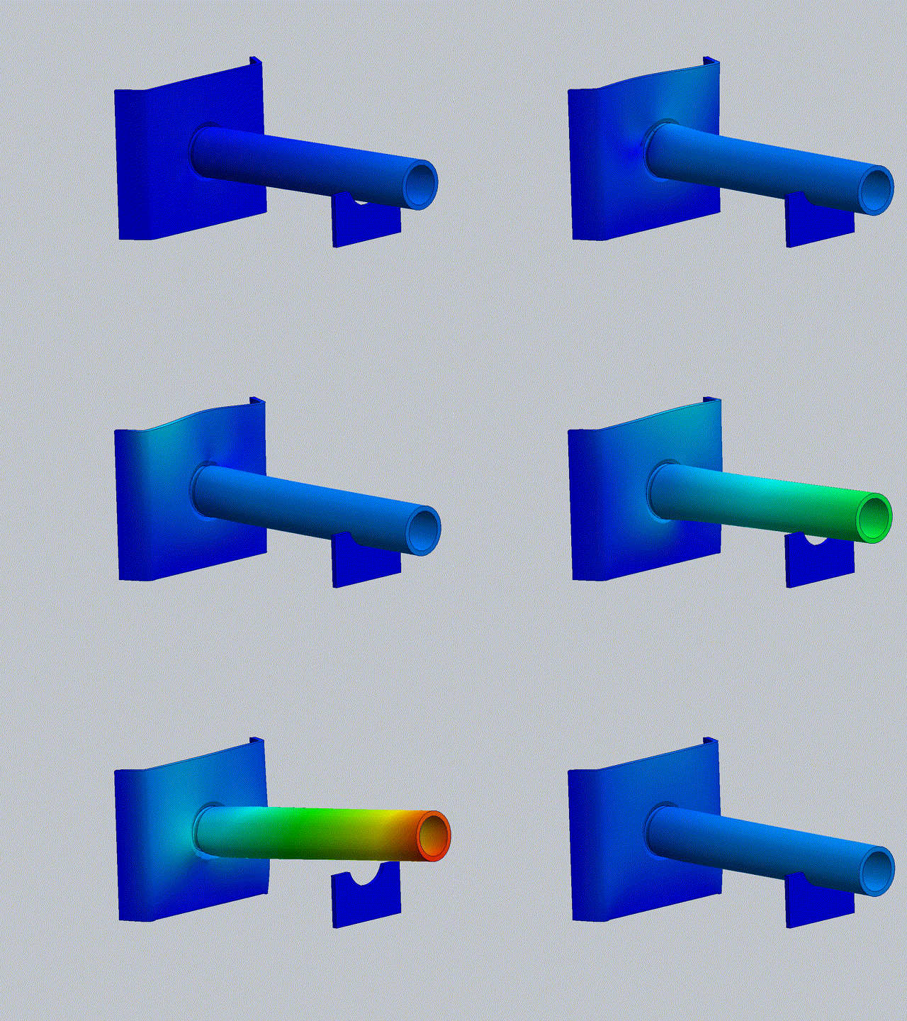
The end goal is to get an accurate displacement plot showing how the components will deform during and after the weld. Figure 19 below shows an animation of the final displacement plot, with the weld bodies removed so we can focus on the components of interest.
Analysis of Results
Looking at the displacement plot in Figure 19, the deflections are dependent on where the weld is along its path. The weld starts at about the 9 o’clock position then moves clockwise. As the weld is in the upper two quadrants of the circular path, the end of the pipe is stabilized by the fixture, and the back plate that it is welded to shows some deformation. As the weld moves through its path to the lower two quadrants, the stresses of the weld force the end of the pipe upwards, which alleviates the deformation from the back plate.
Based on this simulation, a new system for fixing the pipe end could be developed, depending on whether the deformation of the black plate is more (or less) important than the overall position of the pipe’s end. The maximum deflection of the pipe was calculated as 0.266mm (Figure 19 has a deformation scale of 30 applied.)
Final Thoughts on Estimating Weld Distortion in SOLIDWORKS Simulation Premium
Estimating weld distortion is not an easy or straightforward task, as you probably know by now if you’ve made it this far.
There are several assumptions and variables that need to be taken into consideration, and the results from any simulation are only going to be as accurate as the information provided. The method shown in this case study is going to give you the most accurate estimation of your actual deflections during your welds using SOLIDWORKS, but there are other ways you could go about this depending on whether you want even more accurate results or only care about general deflection directions. Let’s assume the actual values of the deflection or not of very much interest.
This could be because the data being input is not reliable, or you just want to get a general idea of the deflections but are not interested in the lengthy setup process shown in this article. There are two major substitutions that can be made to the previous workflow that would speed the process up, both for the setup time and the solving time. First, you could ignore the section on “Accurately modeling geometry”. Rather than creating a clearance gap then sketching your weld bead and using it for a swept cut then swept extrusion, you could simply use the “fillet bead” tool to generate the solid weld body for you.
This body would still need to be split up based on the time to weld, but you’ve already saved a ton of time by not going through those modeling steps. Next, rather than using solid elements, you could use shell elements to speed up the solution time. The shell faces would need to be correctly defined, and the time curve procedure would stay the same, but the solve time would increase dramatically. This process would give you results that have different displacement values, but the directions of the displacements based on the weld positions would remain basically the same.
Going the other direction, there are ways to get even more accurate results outside of the typical SOLIDWORKS simulation package. This requires the use of either Abaqus or 3DX SIMULIA. Both options use a highly advanced and efficient explicit dynamics solver that is ideal for complex contact interactions and extreme deformation. Another huge benefit here would be increased realism, and faster setup as you’d be able to move the heat source around the model without needing the workaround of splitting up the weld or creating all those different staged heat loads. You could run a multi-step analysis and utilize “co-simulation,” which means that multiple solvers are running at the same time and exchanging data with each other. For each time step, the thermal study would transfer the results to the static study, then the static analysis would update the geometry with the new deformations and transfer that data back to the thermal study for the next time step. This would go on for each step until the simulation finishes.
For more information, check out our YouTube channel or contact us at Hawk Ridge Systems today. Thanks for reading!
