Building structural members with SolidWorks is simple and easy, but the final piece of the design can be elusive and ambiguous if you are not familiar with welding and welder codes. Choosing the correct weld size can just be a rule of thumb or guessing game but with SolidWorks Simulation there is an analysis tool that does just that and it is called the Edge Weld Connector.
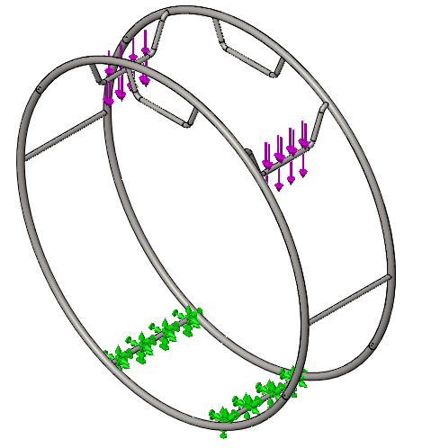
For this blog I am going to be sizing the welds for this circus wheel. It is designed to support the load of a performers hanging from any of the cross bars at any given time. For the simulation I am going to put a 500 lbs vertical load pulling evenly down on two of the cross bars and fix two of the bottom cross bars. This will maximize the stress on the welded connections and be a worst case scenario with multiple performers on the wheel.
|
|
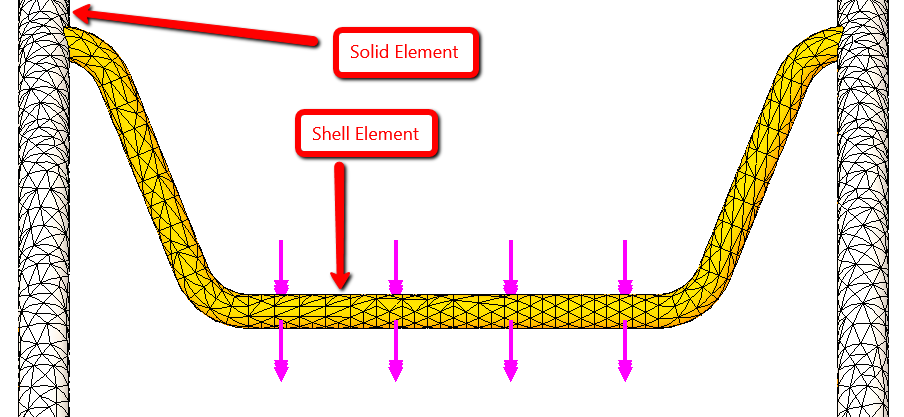
In order to use the Edge Weld Connection inside of SolidWorks Simulation at least one of the components has to have the shell element type. If your mesh is not already using shell elements you need to make sure that the component with the terminating edge that you wish to weld is meshed as a shell element in order to successfully use the Edge Weld tool. In this example, I am going to make my cross bar a shell element because that is the face which terminates to generate an edge.
|
|
Inside the property manager of the Edge Weld the first thing you need to determine is the Weld Type. There are two types of welds available the Fillet and Groove welds. Fillet welds are used when the selected faces are perpendicular to each other and groove welds are used when the selected faces are parallel. Since my faces do not fall into either of that criteria I will test both options and use the worst case scenario. When selecting face 1 you have to select the face of a shell element. This face also has to have the intersecting edge that you are going to select for location of the weld. Face 2 has some more flexibility and can be a solid or shell element.
|
|
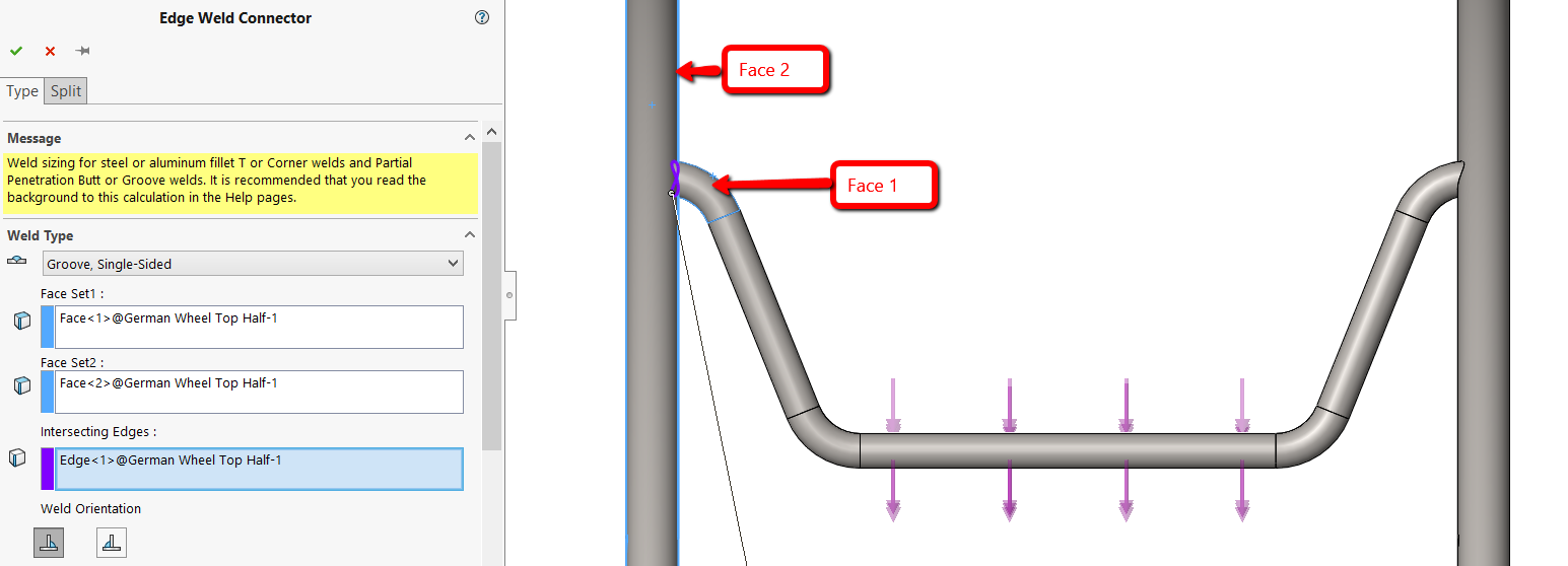
If you are doing a single sided weld you have the option to locate which side of the edge the weld is on. The current selection is indicated by an arrow giving you a clear graphical indication on where the weld is.
|
|
When calculating the size of the weld you have two standards to choose from; The American Standard (American Welding Standard D1.1 and D1.2) or European Standard (Eurocode 3: Design of steel structures, Part 1.8: Design of joints, Section 4.5). I am not going to go in depth about the difference and leave it up to the reader to determine which option is more appropriate for their situation.
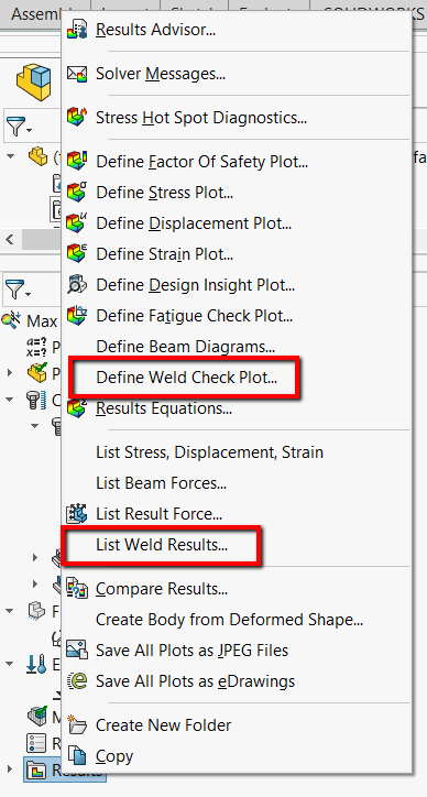
The edge weld connector estimates the appropriate size of a weld needed to attach two metal components by calculating the weld size at each mesh node location along the weld seam. Once the simulation is ran there are 2 ways you can get results about your welds, Weld Results and Weld Check Plot.
|
|
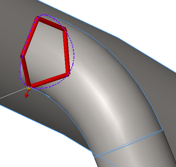
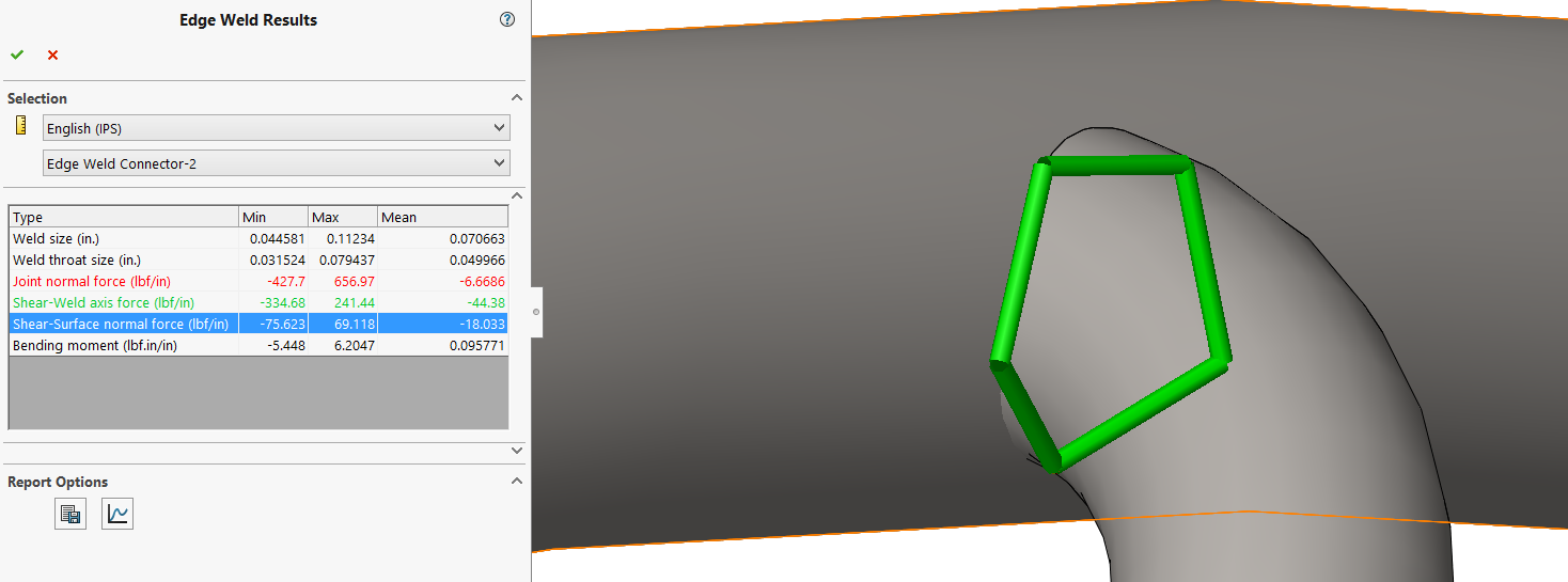
The Weld Results will list the min, max, and mean values along the weld seam. Results are given for the Weld Size, Weld Throat Size, Joint Normal Force, Shear-Weld Axis Force, Shear-Surface Normal Force, and Bending Moment. The weld in the graphics area will be colored green or red representing a pass or fail scenario. You can also generate a plot for the calculated weld size against the position along the weld seam. This can give you insight on where the weld is experiencing the most stress so a choice can be made on intermittent weld locations.
|
|
A weld check plot will display the safety status of all edge weld connectors as well as the calculated minimum weld size. In the graphics area all good welds will be green in colour and all welds that do not meet the safety factor criteria will be displayed in red.
|
|
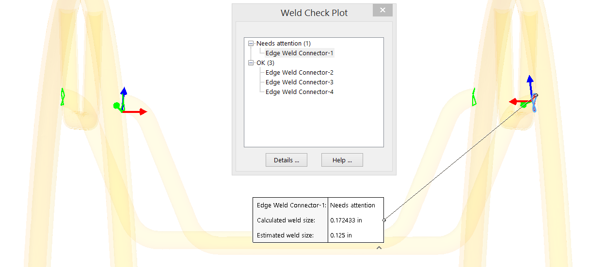
With these tools I could determine that my initial estimate of the weld size of 1/8 of an inch was too small. I got varying results in calculated weld size when I used the groove weld versus the fillet weld but in this scenario the fillet weld was the more conservative choice. I switched the weld size to a 1/4 inch and all the weld checks passed. In summary, the Edge Weld Connection tool is a good way to join your assemblies while getting useful data for determining weld sizes.
For more information, check out our YouTube channel, get a SOLIDWORKS Simulation quote or contact us at Hawk Ridge Systems today. Thanks for reading!