When working on a part-modifications might need to be made. Keeping the original part is desired but doing that means starting a new part from scratch. Starting from scratch just to have a variant of color or even to change dimensions will result in a loss of time. The solution to that problem is to use SOLIDWORKS’ ability to make Configurations from an already existing model. In this blog, we will be going over the steps on how to create proper Configurations and how they can be affected by changes within the different Configurations.
A step-by-step demonstration of SOLIDWORKS Configurations:
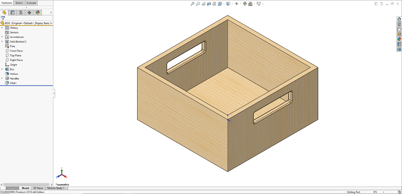
Let’s start with this box that is going to be used to store things away.
 SOLIDWORKS Model Base Design
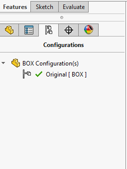
Once the Base Design has been created using standard modeling practices, a new variant or configuration can be specified. It is very easy to start a new Configuration of the box. To create a new variant select on the Configuration Tab of the Feature Manager Design Tree. Right click on the top level and Select Add configuration.
 SOLIDWORKS Configuration Sketch
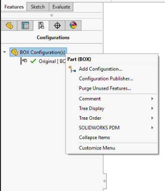
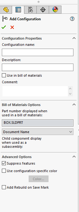
From the right-click menu I can select Add configuration. Now we want to make sure that inside the Configuration Properties under Advanced Options that we have suppressed new features and mates checked off. It’s important to have it checked off to ensure the default configuration does not get any of the changes made to the new configuration.
 SOLIDWORKS – Add Configuration
Next, to the new Configuration, we will find the original one under Default Configuration. Changing names is also possible and follows the same steps as if changing the names of features. A slow double click will work or one click while pressing the F2 key to change the name.
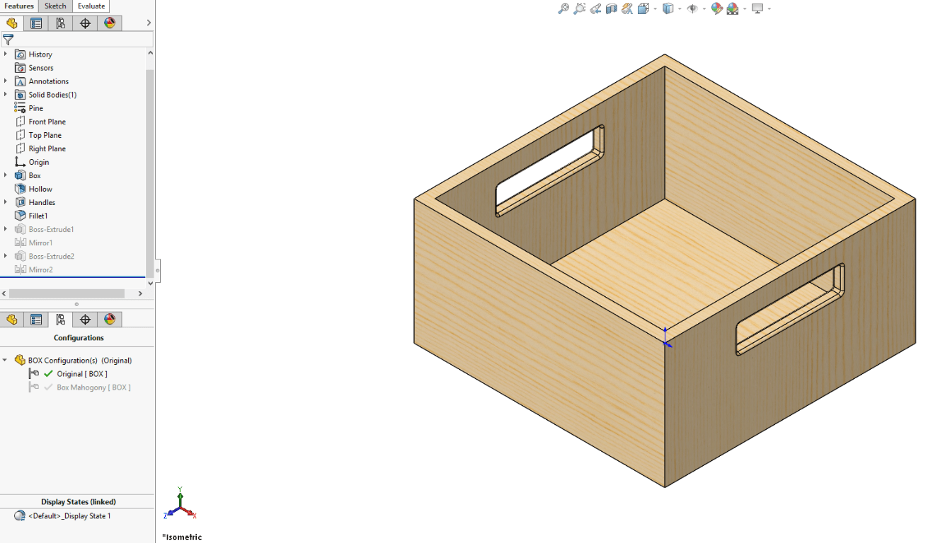
Now that the new configuration has been added changes can be made. The first change is to sketch what will be the trim on the top part of the box. To do that just select one of the flat faces and click on the sketch command inside the Sketch tab. A simple rectangle will do in the sketch. The next step is to extrude the rectangle. The same thing will be done for the face on the width. Both extrusions can be mirrored. Inside the Features tab, the Mirror Feature is clicked on with the rectangle on the length side and the front plane. The extrusion will be mirrored. For the rectangle on the width face, the same process will follow with the exception of selecting the right plane for the Mirror Feature instead of the front. The Mahogany Box’s trim will be finished. The second change is to now change the material to Mahogany wood.
 SOLIDWORKS Configuration – Mahogany Box Trim
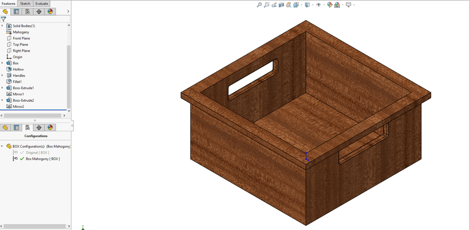
As long as you have the suppress new features option turned on. The features created and material change in the New Configuration will not be physically present in the Default Configuration and be suppressed inside the Feature Manager Design Tree. This can be seen in the figure below.
 SOLIDWORKS Configuration Example
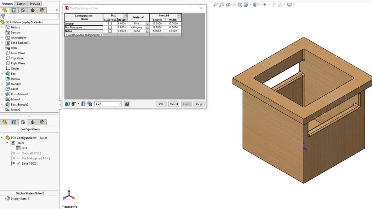
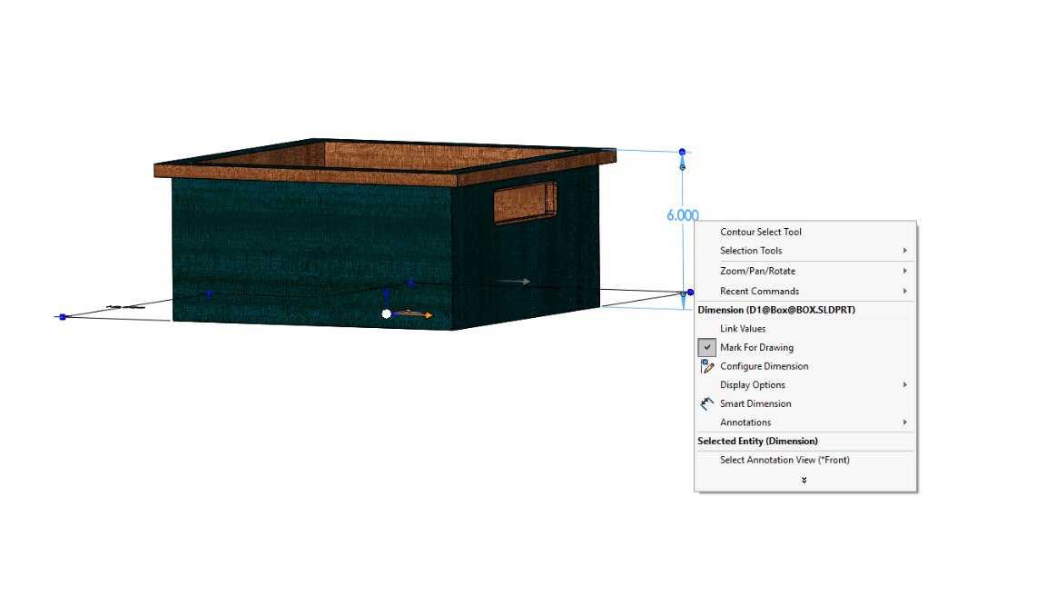
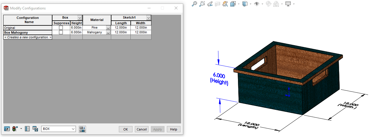
Another box Configuration needs to be added. This time the configuration will be made by using the Modify Configuration Dialogue table. The Modify Configuration Dialogue table can be accessed by right-clicking on a dimension, feature, and Material.
 SOLIDWORKS Configuration Dialogue Table
Once inside the table, it can allow us to make a new configuration as well as control feature suppression, materials or dimensions.
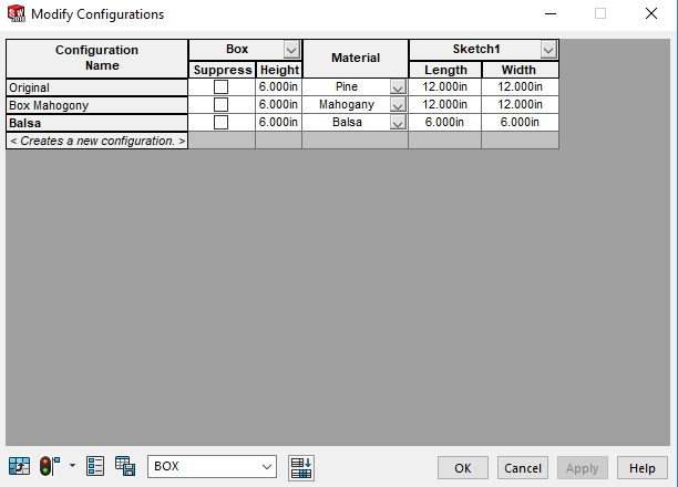
Now the third configuration will be added by typing in the Configuration column. Based on dimensions and materials already in the Configuration Modify Dialogue is what’s available to edit for the new Configuration. This can be seen in the figure below.
 SOLIDWORKS Configuration Column Demonstration
The new Configuration will be named Balsa and have its length and width be six inches. The Material will also be changed to Balsa wood. All these changes were made inside the table without having to go to the features and changing them there.
 SOLIDWORKS Modify Configurations Table
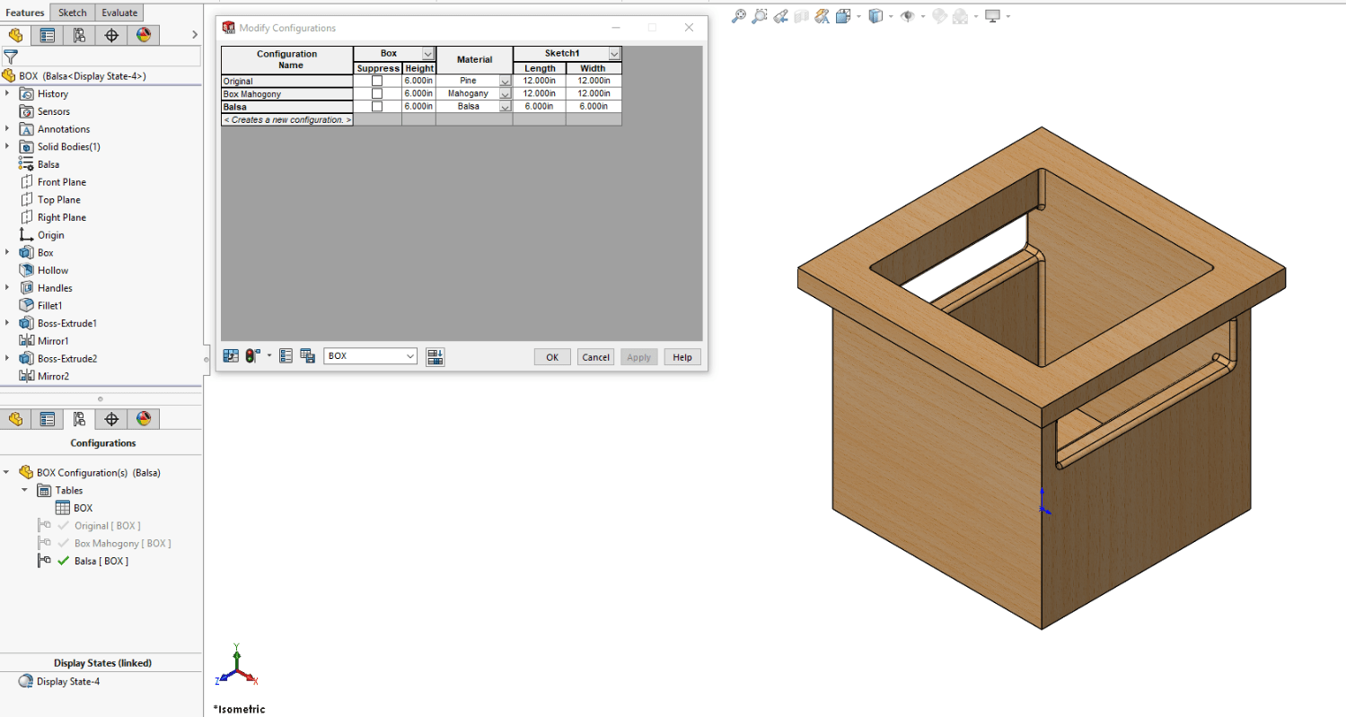
SOLIDWORKS Configuration Box ExampleIn this article, we’ve covered the basics of creating different Configurations. From the easy access to the configuration tab to manipulating dimensions, materials, features, and configurations from the Modify Configuration table. Do you have any additional tips or tricks for using SOLIDWORKS configurations more effectively? Let us know in the comments!
Have questions? Please CONTACT US or get started with a SOLIDWORKS Free Trial


