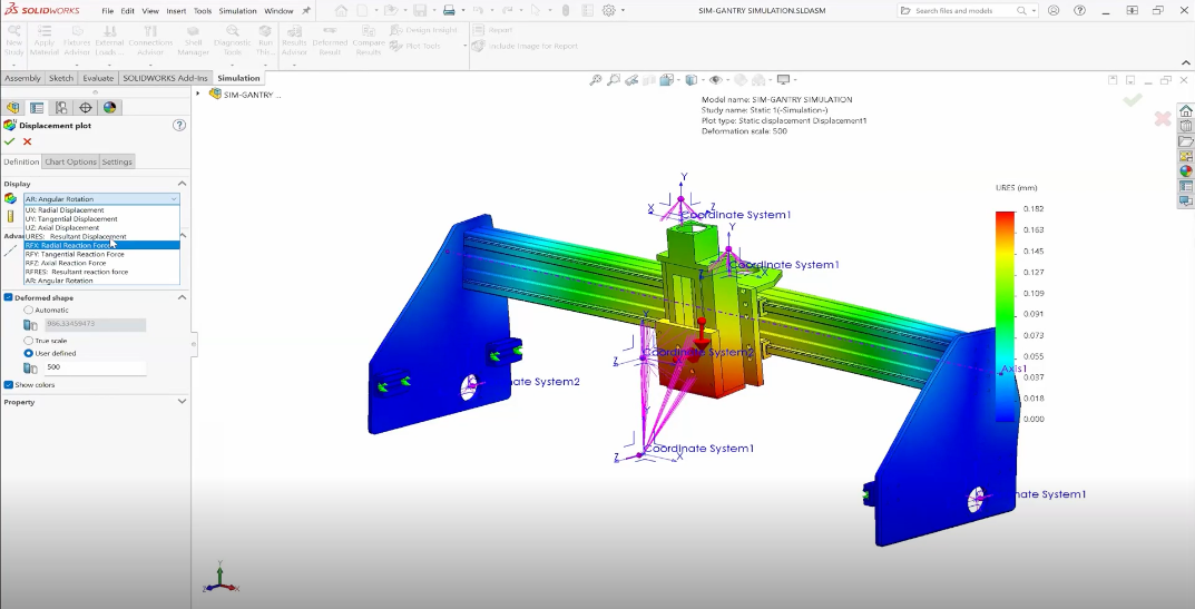
SOLIDWORKS Simulation is a well-known tool in the world of finite element analysis (FEA). Its direct integration with SOLIDWORKS means that we can analyze, update, and validate our models very easily and with high levels of accuracy.
But just because it’s easy to use and can give us accurate results, it doesn’t mean every result is accurate.
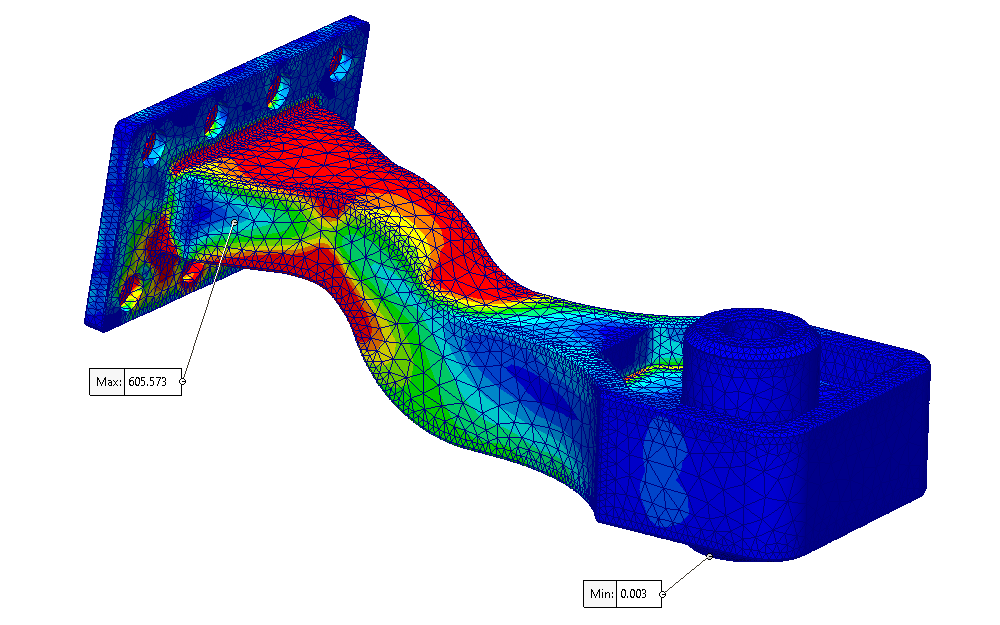
An enormous part of achieving that accuracy depends on us — the user. Accurate results require an accurate study setup utilizing proper engineering and FEA principles in SOLIDWORKS Simulation.
Without proper setup, our study won’t give accurate results because it’s not approximating the real-world scenario we are trying to simulate.
In other words, errors in our setup will result in errors in our results — as the saying goes: “trash in, trash out.”
In this blog post, we will look at where study errors most commonly arise: Fixtures.
Fixtures Are the Reason Why Your Results Are Not Accurate
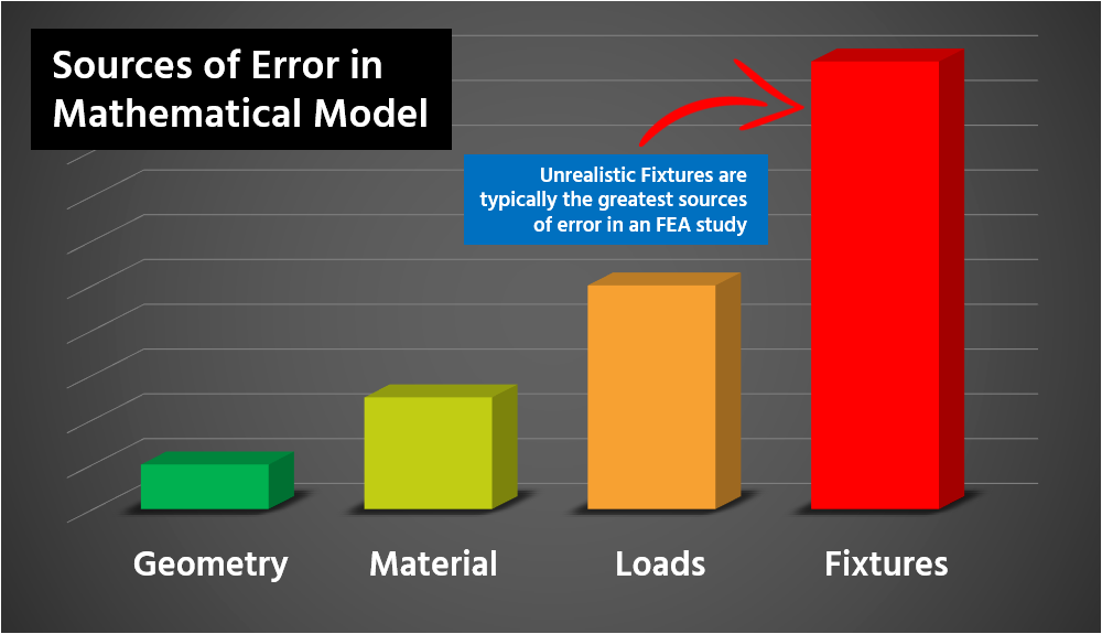
Incorrect fixtures can introduce a significant amount of error in our studies. Incorrect placement or using the wrong fixture type can throw an entire study off.
In fact, sometimes, even a single incorrect fixture can cause our study to deviate so far from the “real world” that the results are essentially meaningless.
First, let’s explore what fixtures are, so we know how to apply them to our studies to achieve accurate results.
What Are Fixtures?
Fixtures, in short, are how we constrain our models in 3D space when conducting analysis in SOLIDWORKS Simulation.
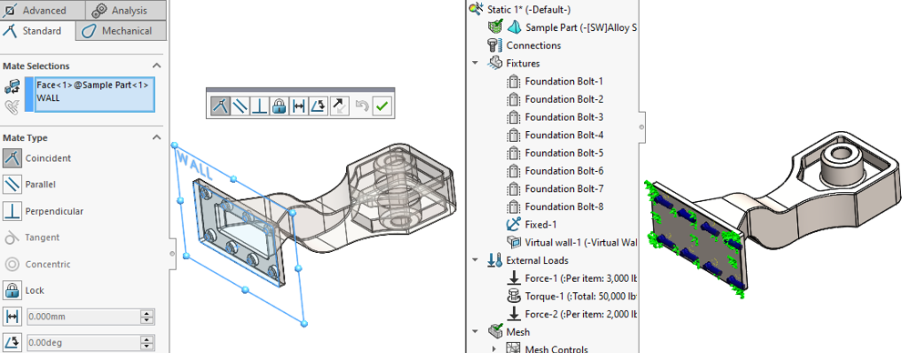
We can think of fixtures as similar to “grounding” mates in an assembly. Mates that “ground” our assemblies are those that establish geometric relationships between assembly components and reference geometry, like planes, origins, or coordinate systems. In other words, they constrain our assemblies in 3D space.
In SOLIDWORKS Simulation, fixtures similarly establish geometric relationships between our model and the 3D environment. They allow us to tell the software how our geometry should be constrained or “fixed” for the purposes of our study.
Fixtures play a huge role in how our model behaves when external loads are applied. As such, it’s critically important that we define them properly to make sure we get accurate results.
I’m sure that almost all of us have created a study with improperly defined fixtures at some point in our design careers, only to run the study and have our model fly off into “no man’s land.”
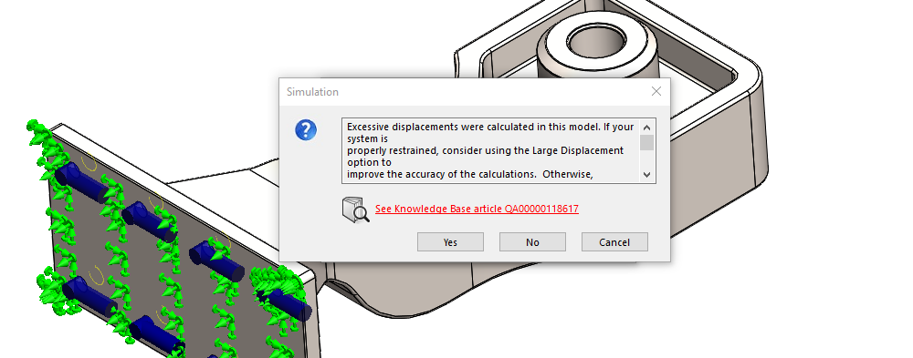
When this occurs, we call it “rigid body motion.” This means that our geometry wasn’t properly constrained and, as a result, instead of deforming, our model simply moves off in space in whatever direction the external loads are pushing it.
Consequently, no stress results are reported, and nothing useful is learned about our model. Ensuring we have proper constraints on our model is paramount to getting accurate results.
PRO-TIP: Seeing a “large displacement” warning when we aren’t expecting large displacements is generally a good indicator that our model is under-constrained because our fixtures are not properly defined.
You can also think about fixtures as mechanisms to establish boundary conditions (BCs) for a simulation study. They let us bound the scenario we are trying to simulate and define what happens at those boundaries.
By bounding our studies properly, we can significantly simplify the problem we are trying to solve with SOLIDWORKS Simulation while maintaining accuracy.
Understanding Fixtures as Boundary Conditions
Thinking of fixtures as boundary conditions help us define the “system” we want to analyze. And when analyzing any system, we need to ask ourselves: What are the bounds of that system?
In the real world, there are no practical “bounds” — nothing exists in a vacuum and no system is truly “closed.” Every event or action influences the environment around it, even if the effect is very small.
*NOTE: What is really being applied to a study when we solve it are the boundary conditions for the differential equations used to find a solution via FEA. We are discussing boundary conditions in a global/macro sense here, but those are directly tied to the boundary conditions of the differential equations that SOLIDWORKS Simulation is solving.
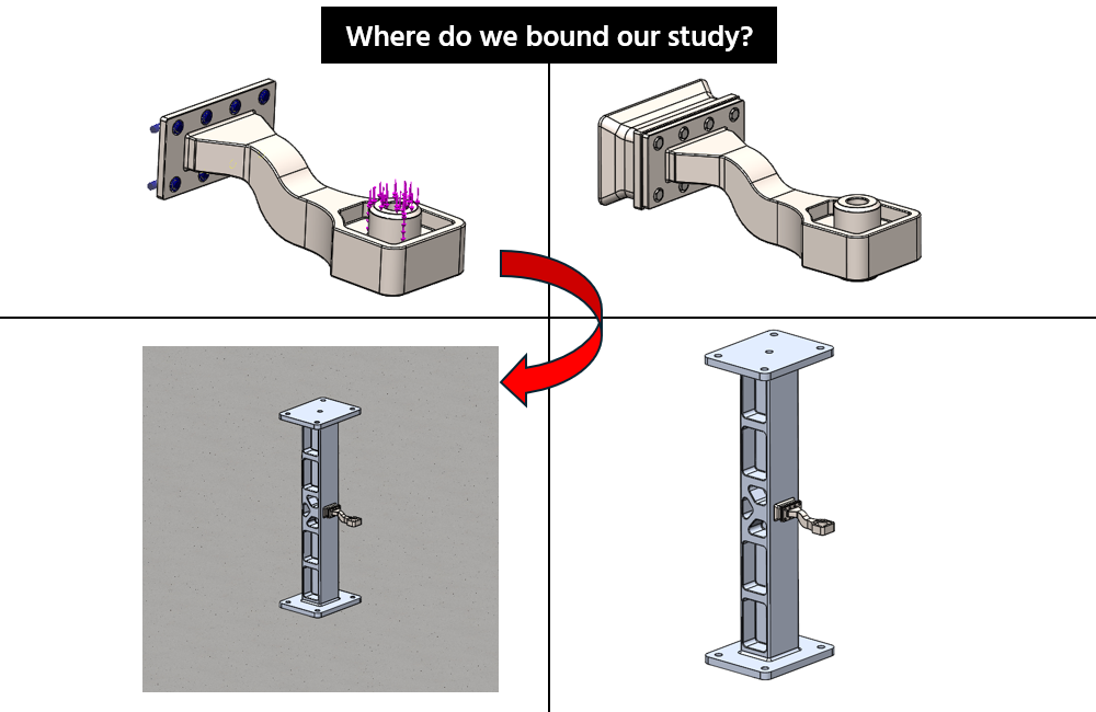
Any time a load is applied to a physical part, that load goes beyond just that single part. In reality, the load is supported by and transferred to the components around that part through, what we call, the “load path.”
The load path continues to the assembly our part belongs to, onto the larger system, which might be supported by the floor, then the foundation, then into the ground, and so on.
And the entirety of that load path influences how our part will behave.
Properly Bounding Your Study
So, how do we model all of that for our study? Well, the answer is: we don’t!
We need to draw a line somewhere. If we don’t define a cut-off point, our study will be far too complex to solve. Therefore, we need to ask ourselves what along that load path is significant and what is our area of interest.
Once we make that determination, we can then bound our problem accordingly to significantly simplify our study. And fixtures are one of the primary ways we create those bounds.
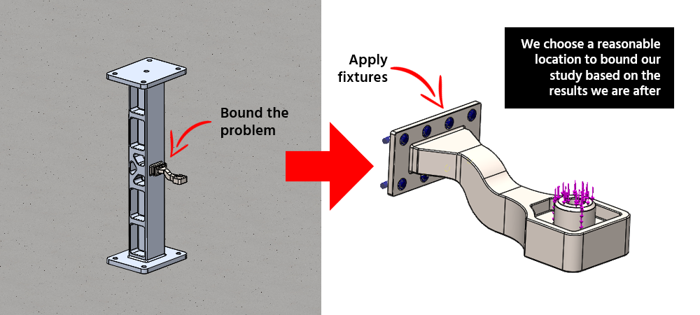
It’s important to remember that boundary conditions represent significant assumptions we are making in our study.
For many studies, we can assume that things like the foundation of the building will have negligible effect on our results. We essentially treat it as rigid, as the deformation of the building foundation isn’t significant for most studies. This is a good assumption for many cases but is still an assumption.
We are purposefully excluding a part of the real-world scenario to make our study simpler. We, as engineers, determine when those assumptions are valid.
The bottom line is fixtures represent assumptions with how our system is bounded. If we make valid assumptions by setting up our fixtures properly, we can get very accurate results while conducting very simplified studies.
How to Apply Fixtures Correctly
Applying fixtures may seem very straightforward — pick the fixture type you want and click on the geometry that you want it applied to.
Easy, right? Well, not so fast.
We need to consider a few things when applying fixtures if we want accurate results.
PRO-TIP: Our SOLIDWORKS Simulation Course covers fixtures and their application in far more detail than we have time to cover in this blog. Be sure to check out that course if you want to get familiar with FEA.
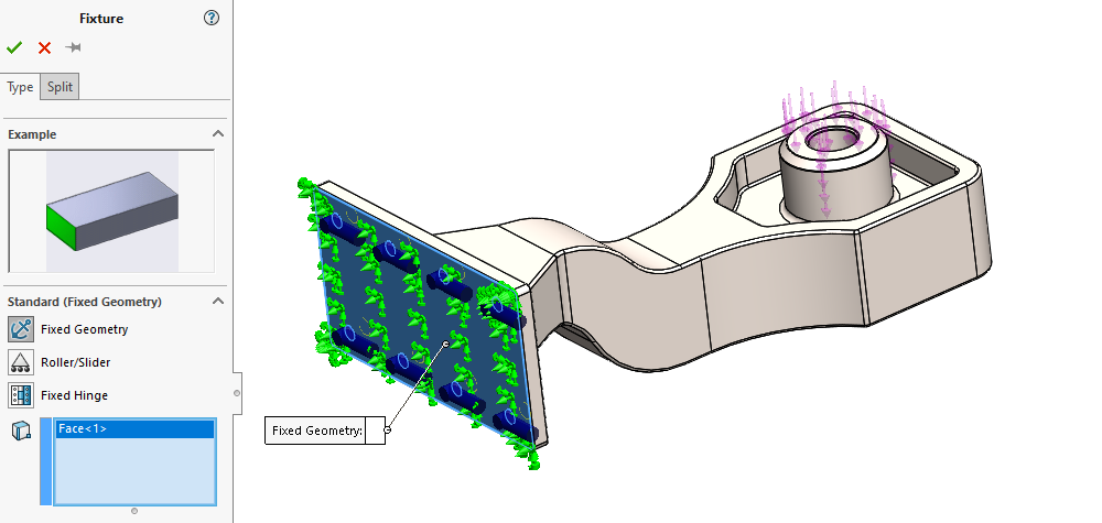
We know our goal with fixtures is to constrain and bound the problem we are trying to solve, but we need to choose those bounds properly. It is up to us to use our engineering knowledge and skills to determine what those bounds should be.
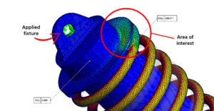
For example, if we are trying to analyze the stress of a spring in a car’s suspension, we probably don’t need to model the entire car.
But could components make the cut? What should be excluded? What should be included as a part of our “system?”
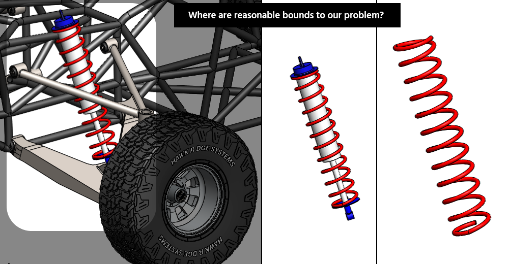
The answers to these questions are most often driven by what we call our “area of interest.”
- Do we care about the stresses in the spring itself?
- Do we care about the contact pressure between the spring and its mounts?
- Do we want to find out if the spring mounts are strong enough?
- Do we need to evaluate the load paths from the spring to other suspension components?
Depending on our answers to these questions, the bounds of our problem, and therefore our fixtures, it can look very different.
Determining Your Areas of Interest, Study Bounds, & Fixture Placement
Evaluating our application and asking ourselves what’s important is a critical step in the analysis process before creating our first fixture in SOLIDWORKS Simulation.
In fact, before clicking that “New Study” button, we should be asking:
- What’s the purpose of this study?
- What specific data am I looking for?
By asking ourselves questions like these, the bounds of a study and where we should apply our fixtures should naturally come into view.
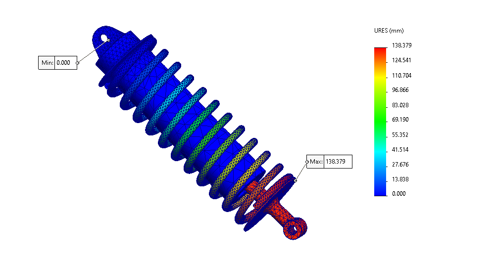
A good general rule of thumb is to keep our fixtures sufficiently far away from our area of interest.
Since fixtures can introduce a significant amount of error, naturally, we want to keep that error away from the geometry we are interested in.
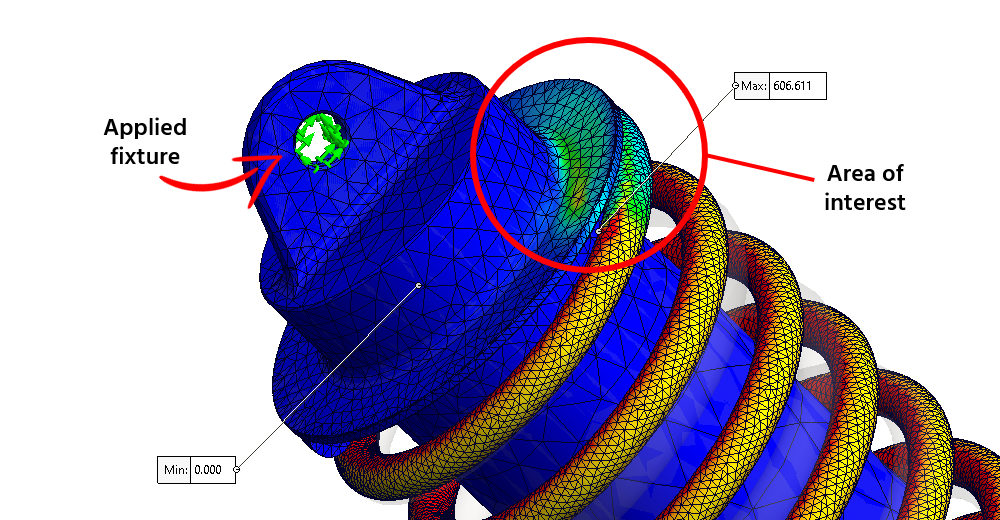
Determining where the cut-off for “sufficiently far away” depends on our application. Making that determination becomes easier the better we understand the application, the purpose of our study, and the principles of FEA.
Continue Learning About Fixtures in SOLIDWORKS Simulation
To continue learning about fixtures in SOLIDWORKS Simulation and how to use them, be on the lookout for follow-up posts discussing the specific Fixture types. We’ll soon be posting content on both Standard and Advanced Fixtures in SOLIDWORKS Simulation. We’ll discuss how to use each Fixture type, scenarios and applications where they are best used, and the implications of applying them. So, stay tuned!
If you’re interested in other SOLIDWORKS Simulation blog posts, check these out:
- Testing Assumptions in SOLIDWORKS Simulation: In this blog post, we explore how to set the bounds of studies.
- SOLIDWORKS FEA – Simulation Analytics: 3 Golden Rules: We dive into things you should look for when setting up your own studies.
As always, if you have any questions, reach out to us at Hawk Ridge Systems, and we will help you on your journey in the world of FEA. We are here to help be part of the solution to your design and engineering challenges.
