In this post, I’ll walk through what I shared at the Design2Manufacture digital conference — how topology optimization in CATIA takes simulation-driven design from concept to reality, enabling workflows and levels of control that go beyond what SOLIDWORKS alone is designed to support. We’ll explore what topology optimization is, how it’s evolved since my first SOLIDWORKS project over 5 years ago, and why it’s a cornerstone of the generative design workflow.
A Throwback to 2019: My First Topology Experiment
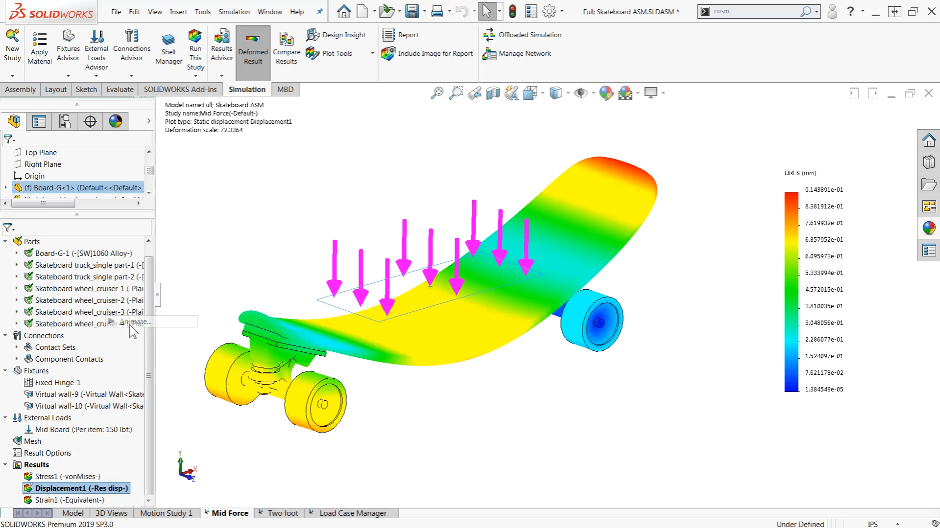
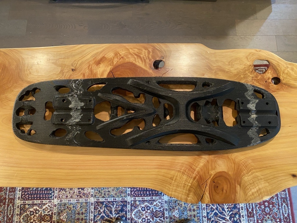
Back in 2019, I published a YouTube series where I designed and 3D-printed a penny-board-sized skateboard using SOLIDWORKS Topology Study. The goal was simple — make something light, strong, and fun to ride. It was printed on a modified Creality CR-10 using carbon fiber nylon filament. Despite the experimental setup, the board held up remarkably well through daily rides, city commutes, and even a few trips strapped to my luggage.
Fast Forward: Why Revisit This in CATIA?
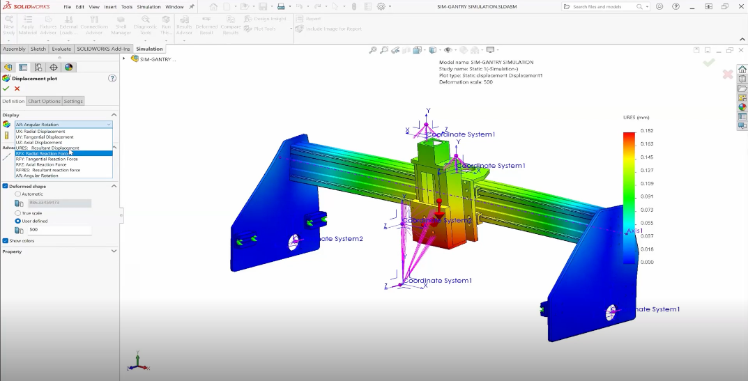
Half a decade later, I wanted to see what’s changed. CATIA on the 3DEXPERIENCE platform brings topology optimization to a whole new level — and not just because it looks cool (it does). It’s faster, smarter, and way more flexible. You can run analyses at the assembly level, define multiple load cases, and compare manufacturing constraints like casting vs. milling to generate practical, buildable results.
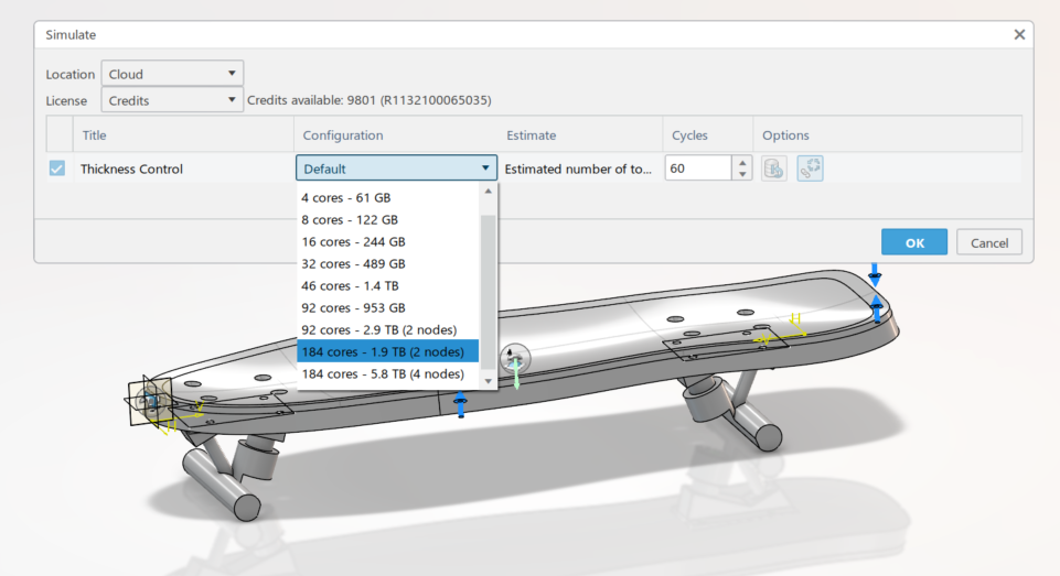
Another game-changer: cloud computing. In CATIA, you can send your topology optimization to the cloud, freeing up your local system while crunching through heavy simulations in parallel. That means more iterations, more exploration, and less waiting around for progress bars.
Quick Overview: What is Topology Optimization?
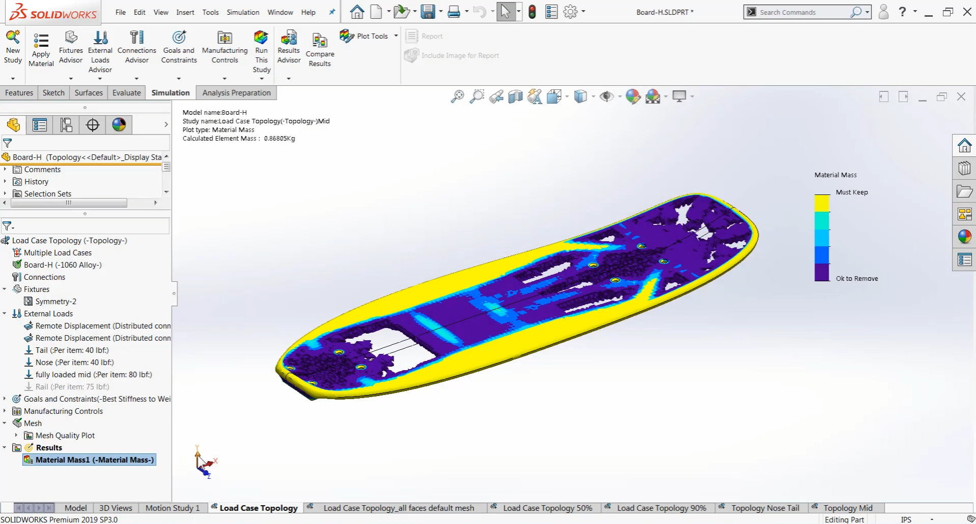
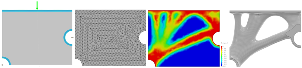
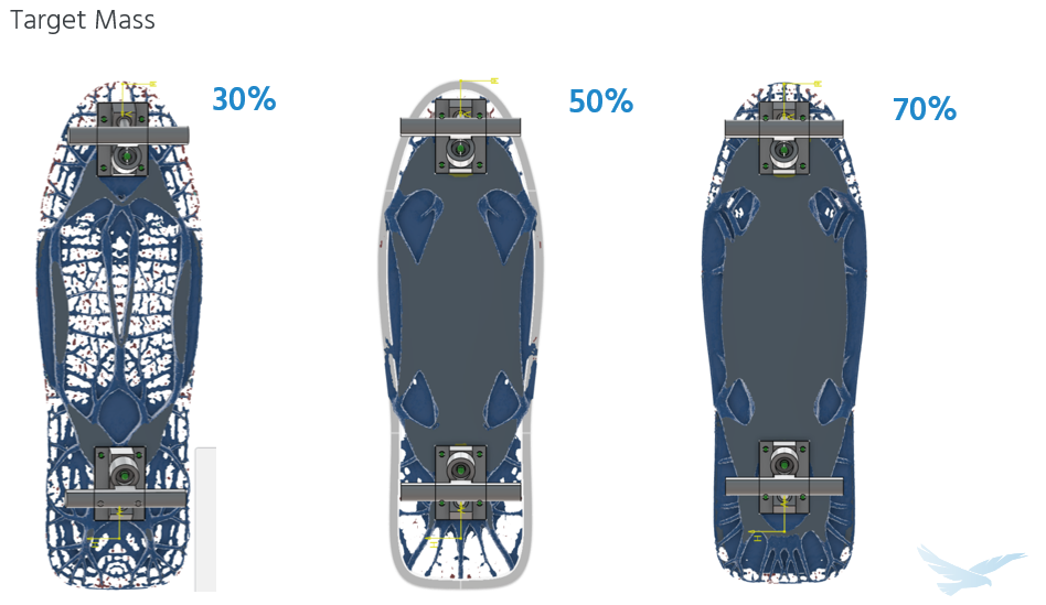
In simple terms, topology optimization is a way for the computer to tell you where your design does — and doesn’t — need material. You start with a design space (a block of material), apply loads and constraints, and let the software remove material where it’s less structurally necessary. The result is an organic, efficient shape that’s lighter but retains strength.
In traditional design, we add material for safety. In topology optimization, we start with too much and let the computer carve it away. The trick is interpreting the result and refining it for real-world manufacturing — that’s where CATIA really shines.
Topology in CATIA: Small Steps, Big Upgrades
While my first SOLIDWORKS topology project was an exciting challenge, CATIA takes that workflow further. Here’s what stood out most in my recent project:
- Easier setup and management of multiple load cases
- Ability to optimize at the assembly level
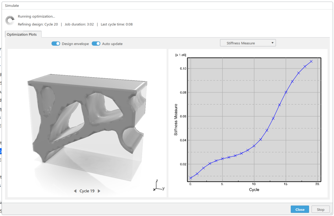
- Simulation checks before running optimization (helps verify setup and define realistic displacement targets)
- Real-time mass preview during optimization
- Multiple concept managers for different design targets
- Output options: Sub-D or mesh — editable results for refinement
- Post-topology validation directly on the new geometry
Old vs. New: Side-by-Side
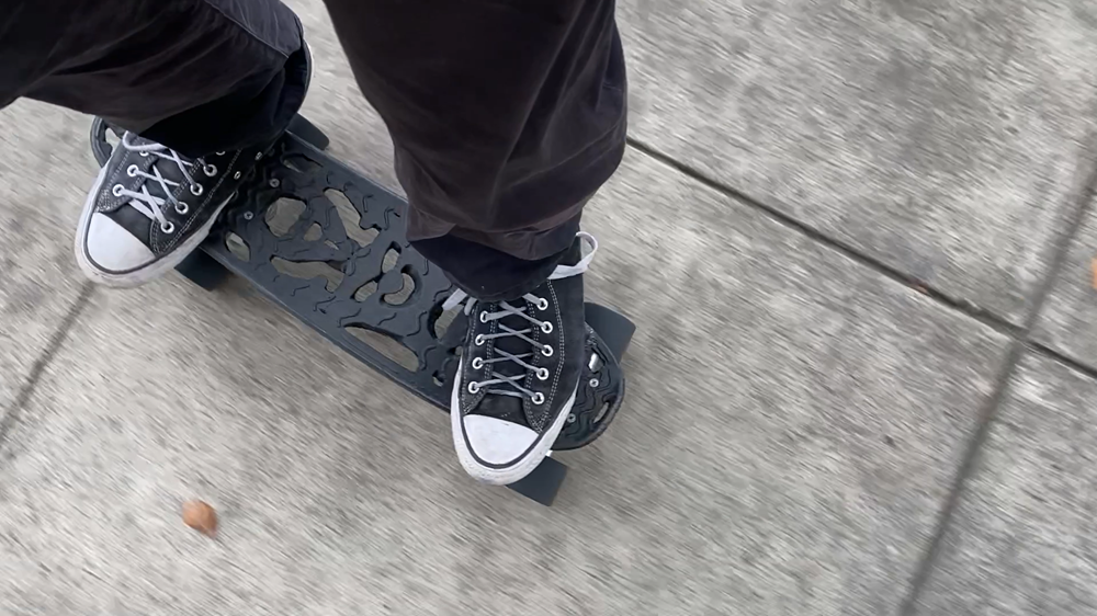
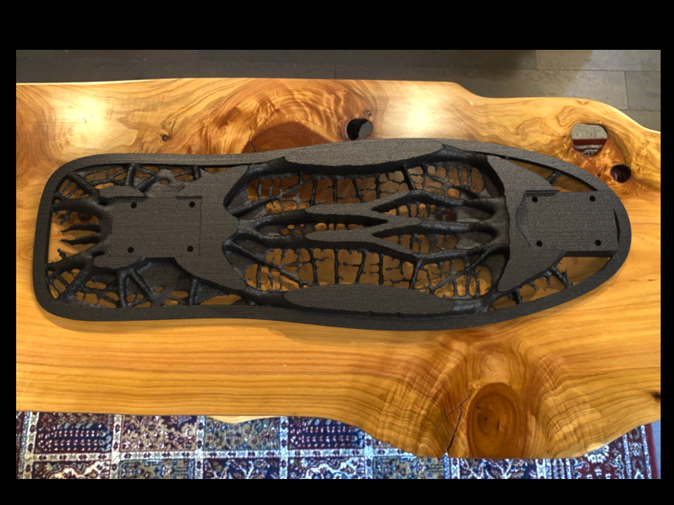
Finally, I brought the two designs together — the original SOLIDWORKS board and the new CATIA-optimized concept. For now, the new design only exists as a render in SOLIDWORKS Visualize (call it a teaser). Printing is on the way, but perfectionism may have gotten the better of me!
What’s Next: Printing, Testing, and Deep Dives
This blog is just the start. In upcoming posts, I’ll dig into the full CATIA setup process step-by-step, including the specific study parameters and workflow. I’ll also cover what we didn’t get to in the presentation — the analysis of the topology result, the post-topology manufacturing features, and yes, the testing of the printed board itself.
I’ll also publish a blog dedicated to how the model was created in CATIA (sketches, features, parts, assemblies) — because that’s an area where we could all use more real-world examples. And if you’re curious about the Visualize fake-out render? Let me know — maybe that deserves its own post too.
Until then, keep designing, keep optimizing, and keep skating!
Check out the full D2M Session, “Topology Optimization in CATIA for Advanced Engineering,” or check out these other resources covering CATIA:
Why CATIA’s Surfacing Capabilities Drive Precision in Automotive Design
3 Steps to Easily Import CATIA Files into SOLIDWORKS
The Best of Both Worlds: Working with CATIA Files in SOLIDWORKS 3D CAD
Frequently Asked Questions about CATIA & Topology Optimization
Q: How does mesh density affect the optimization results?
A: Mesh density directly impacts the level of detail in your optimized design. Since topology optimization works by evaluating and adjusting the density of individual mesh elements, the size of those elements determines the smallest features that can be created or removed. A finer mesh (smaller elements) allows for more intricate design features and precise material distribution, while a coarser mesh produces more generalized results but solves faster. It’s important to note that feature size is also influenced by filtering and minimum member size controls, not just element size. In CATIA, you can test different mesh resolutions and use cloud computing when running higher-resolution studies.
Q: Can CATIA handle multiple loading conditions in a single optimization?
A: Yes, CATIA excels at multi-load case optimization. The system allows you to define several distinct loading scenarios (such as different user positions, operational modes, or stress conditions) and will generate an optimized design that performs well across all specified cases. You can also control which specific performance metrics matter for each load case. This is particularly valuable for products that experience varying forces during operation, ensuring the final design is optimized for all real-world usage scenarios rather than a single condition.
Q: What happens after the optimization is complete? How usable is the result?
A: CATIA offers expanded post-optimization workflows compared to SOLIDWORKS. You can export the optimized result as either a tessellated mesh or as a subdivision surface model, providing greater flexibility for refinement and controlled geometry edits.
The subdivision surface workflow allows you to smooth transitions, locally adjust material, and reshape the optimized form as it moves toward a manufacturable design. As with any topology result, geometry modifications should be revalidated to ensure performance targets are still met.
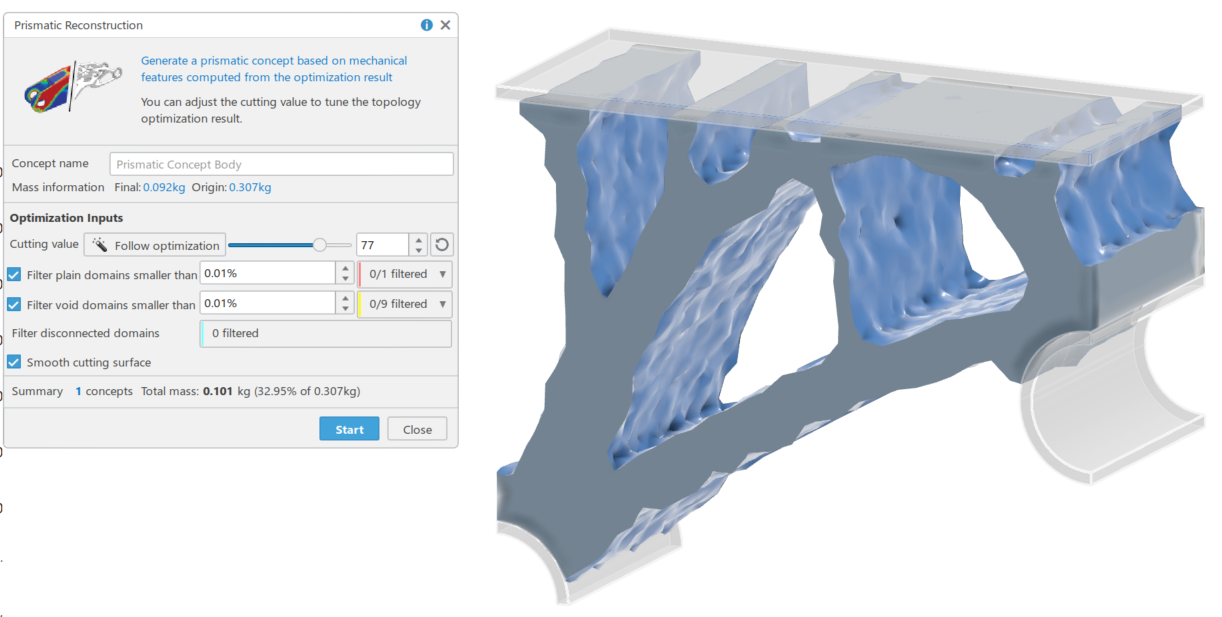
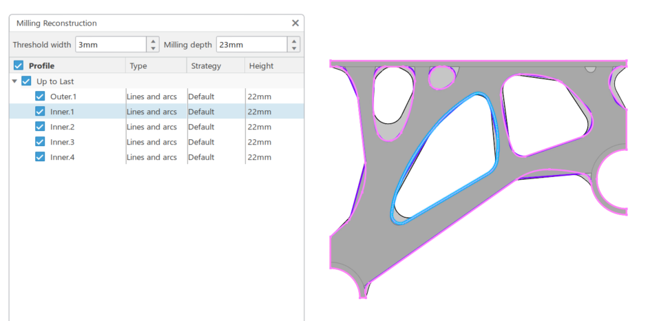
CATIA also includes tools to help transition organic topology output into manufacturing-friendly geometry — such as reconstructing regions into standard arcs and lines with defined minimum radii — making it easier to develop a parametric, production-ready model.